FunkTronic Major 4a User manual

Major 4a
Major 5a
Software Option
Kenwood NEXEDGE
Software Option
Kenwood NEXEDGE

m4a_5a_kenwood_nexedge_eng (09.10.2014)
- 2 -
Kompetent für Elektroniksysteme
m4a_5a_kenwood_nexedge_eng (09.10.2014) - 3 -
Kompetent für Elektroniksysteme
Contents
Order Information 2
General Information 3
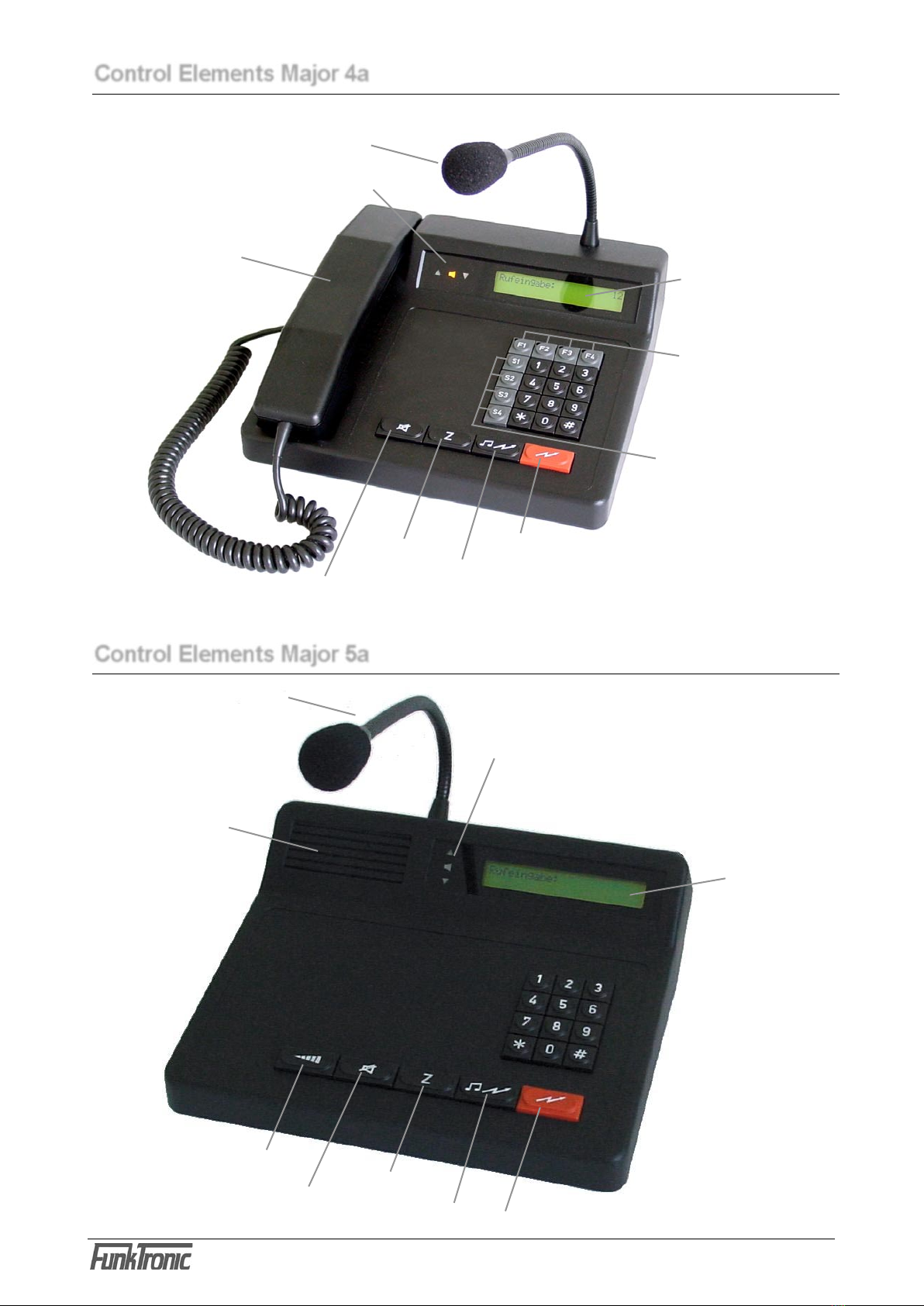
Control Elements Major 4a 4
Control Elements Major 5a 4
Display Elements Major 4a / 5a 5
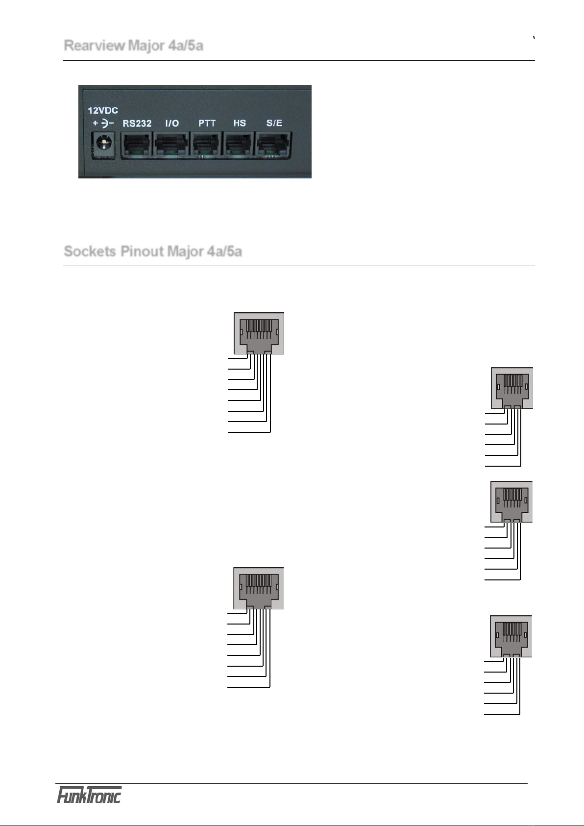
Sockets Pinout Major 4a/5a 6
Rearview Major 4a/5a 6
RS232 Interface 7
RS232 Cable for Flashing/Printing/Monitoring 7
Configuration of the RS232 Interface 7
Example Configurations 8
Standard Keypad Assignment Major 4a 9
Standard Keypad Assignment Major 5a 9
Keypad Assignment Major 4a in Programming Mode 10
Keypad Assignment Major 5a in Programming Mode 10
Differences Major 4a - Major 5a 10
Menu Structure 11
Configuration of the Software 14
Programming Short Call 14
Changing the Assignment of Button Functions 15
Customizing the Call Input 16
Reset to Factory Defaults 16
Transmit/Receive SDS 17
Analog Channels 17
ACK Request 17
Default Group Call (since V3.06) 17
Table of Registers Major 4a/5a 18
Programmable Functions 21
Technical Data 23
Tontabelle 23
Important Settings at the Kenwood Radio 24
General Safety Information 26
Returning of Old Equipment 26
Release Notes 27
Page
Order Information
Order No. Description
681000.NX Major 4a incl. Option Kenwood NEXEDGE
714000.NX Major 5a incl. Option Kenwood NEXEDGE
903050 Distribution Frame (Überleitverteiler) DMR, 2-fold
903051 Distribution Frame (Überleitverteiler) DMR, 3-fold
Distribution Frame (Überleitverteiler) DMR, available on demand up to 9-fold
Attention: If needed, a power supply unit is available separately:
900012 Power Supply Unit 230V/12V for Major 4a + Major 5a

m4a_5a_kenwood_nexedge_eng (09.10.2014)
- 2 -
Kompetent für Elektroniksysteme
m4a_5a_kenwood_nexedge_eng (09.10.2014) - 3 -
Kompetent für Elektroniksysteme
In order to allow direct connection to a digital radio of the Kenwood NEXEDGE series, Major 4a and
Major 5a can be equipped with the software option Kenwood NEXEDGE.
General Features :
General Information
- alphanumeric LC display with background lighting
- gooseneck microphone with high dynamic range
- plaintext menu structure for simple programming via the keypad
- all buttons are freely programmable
- two functions can be assigned to each button
- A Kenwood NEXEDGE radio can be directly connected
- A Kenwood NEXEDGE radio can be remotely connected (Audio-USB Interface-Box)
- Two sockets for control via headset, one of those for connection of a PTT foot switch
- 7 digital In/Outs for channel switching or other purposes
- operates via an external 12V-DC power supply

m4a_5a_kenwood_nexedge_eng (09.10.2014)
- 4 -
Kompetent für Elektroniksysteme
m4a_5a_kenwood_nexedge_eng (09.10.2014) - 5 -
Kompetent für Elektroniksysteme
Control Elements Major 4a
handpiece with
PTT button
gooseneck microphone
loudspeaker (LS)
button
call button
short call button PTT button
LC display
function buttons
special buttons
status LEDs
Control Elements Major 5a
loudspeaker
gooseneck microphone
loudspeaker button
call button
short call button
PTT button
LC display
status LEDs
volume button

m4a_5a_kenwood_nexedge_eng (09.10.2014)
- 4 -
Kompetent für Elektroniksysteme
m4a_5a_kenwood_nexedge_eng (09.10.2014) - 5 -
Kompetent für Elektroniksysteme
Display Elements Major 4a / 5a
LC Display
All alphanumeric readouts are presented by a LC display with background lighting.
Status LEDs
Carrier Display (Squelch)
The carrier display LED can be controlled by voice (2-wire connection) or via squelch input
(using the radio set). If the light is on, the radio circuit is occupied, that is, a carrier signal
(carrier is keyed) is present.
PTT Display (Push-to-Talk)
The PTT display LED is on, if the transmitter is keyed. Keying of the transmitter is achieved
by pressing the PTT button during telephony or by sending a call.
Loudspeaker Display (Incoming Call)
The loudspeaker display LED is on, if the loudspeaker or the earphone capsule in the
handpiece are switched on.

m4a_5a_kenwood_nexedge_eng (09.10.2014)
- 6 -
Kompetent für Elektroniksysteme
m4a_5a_kenwood_nexedge_eng (09.10.2014) - 7 -
Kompetent für Elektroniksysteme
PWR operating voltage 12V, max. 1,5 A
inside: positive terminal, outside: GND
Rearview Major 4a/5a
Pinout I/O
Digital In/Outputs (ST3)
IN/OUT 0 1
IN/OUT 1 2
IN/OUT 2 3
IN/OUT 3 4
IN/OUT 4 5
IN/OUT 5 6
IN/OUT 6 7
GND 8
Pinout RS232
(ST4)
NC 1
NC 2
TxD 3
RxD 4
GND 5
NC 6
Pinout S/E
Radio Circuit (ST1)
AF input B 1
AF input A 2
Squelch input 3
GND 4
output +12 V, max. 200 mA 5
PTT active, low 6
AF output A 7
AF output B 8
Pinout PTT
Headset (ST2)
GND 1
GND AF input (mic. -) 2
NF earphone 3
GND earphone 4
AF input (mic. +) 5
PTT, active GND 6
Sockets Pinout Major 4a/5a
All AF in/outputs are equipped with transformers
and, hence, potential-free. PIN 5 is for supply
(+12V) of external devices (LIM-AC, FT634C).
Attention: Do not use PIN 5 to supply a radio
set. 200 mA output current is not sufficient.
There are two sockets for connecting a headset.
One is for connecting the headset, the other
for the use of an external PTT button (e.g. foot
switch)
The digital connections can be configured as
inputs or outputs, respectively. Usually, these are
used as outputs for remote channel select.
All of the schemes show the sockets as viewed from the rear of the Major.
ST1
ST2AST4 ST2ST3PWR
Pinout HS
Headset (ST2A)
GND 1
AF input (mic. +) 2
AF earphone 3
GND earphone 4
GND AF input (mic. -) 5
PTT, active GND 6

m4a_5a_kenwood_nexedge_eng (09.10.2014)
- 6 -
Kompetent für Elektroniksysteme
m4a_5a_kenwood_nexedge_eng (09.10.2014) - 7 -
Kompetent für Elektroniksysteme
5 GND
ST4 RS232 Interface
RS232 Interface
Pinout
RS232 ST4
1
2
3
4
5
6
RS232 Cable for Flashing/Printing/Monitoring
7 GND
2 TxD RS232
3 RxD RS232
RS232 25pin connector on computer RS232 socket on Major
TxD
RxD
GND
Pinout
RS232 ST4
1
2
3
4
5
6
TxD
RxD
GND
3 TxD RS232
2 RxD RS232
RS232 9pin connector on computer RS232 socket on Major
Configuration of the RS232 Interface
9600 Baud, 8 data bits, no parity, 1 stop bit, no protocol

m4a_5a_kenwood_nexedge_eng (09.10.2014)
- 8 -
Kompetent für Elektroniksysteme
m4a_5a_kenwood_nexedge_eng (09.10.2014) - 9 -
Kompetent für Elektroniksysteme
RS232
Audio, UBAudio, RS485
3
/
/
6
Remote Control of the Radio
Several Control Panels, remotely Connected to the Radio
8
/
RS232
3
/
/
6
Major 4a
Audio, UB
Direct Connection to the Radio
Major 4a
RS232
Audio, UB
3
/
/
6
Audio, RS485
Audio, RS485
RS232
Audio, UB
3
/
/
6
RS232
Audio, UB
3
/
/
6
8
/
USB
Audio, UB
4
/
/
6
\ 8
Major 4a
Major 4a
Distribution Frame DMR
Example Configurations

m4a_5a_kenwood_nexedge_eng (09.10.2014)
- 8 -
Kompetent für Elektroniksysteme
m4a_5a_kenwood_nexedge_eng (09.10.2014) - 9 -
Kompetent für Elektroniksysteme
0 ... 9 : number input (call, channel, status...)
* short : delete last number
* long : delete whole call input
# short : scroll through ID-code memory
# long : delete ID-code from memory
: channel input
: PTT gooseneck mic / status
: toggle selective call / group call
Z : switch to status input (if a complete call
is entered in the display)
: volume control
¡13
5
4
8
2
0
9
*
7
6
#
A
EF
+
-
S1
¡
B
S2
¡
C
S3
¡
D
S4
Standard Keypad Assignment Major 4a
1 3
54
8
2
0
9
*
7
6
#
A B C
D E F
Standard Keypad Assignment Major 5a
Comparable to Major 4a, but without the additional buttons
S1...S4 and F1...F4.
+
-

m4a_5a_kenwood_nexedge_eng (09.10.2014)
- 10 -
Kompetent für Elektroniksysteme
m4a_5a_kenwood_nexedge_eng (09.10.2014) - 11 -
Kompetent für Elektroniksysteme
Keypad Assignment Major 4a in Programming Mode
Button reduces by 1, button increases by 1.
The values A - F are assigned to the buttons
S1...S4, * and #.
¡13
5
4
8
2
0
9
*
7
6
#
A
EF
+
-
S1
¡
B
S2
¡
C
S3
¡
D
S4
1 3
54
8
2
0
9
*
7
6
#
A B C
D E F
Keypad Assignment Major 5a in Programming Mode
Long pressing of buttons 1 to 6 results in the
additional values A-F..
The call button reduces by 1, and the red PTT
button increases by 1.
+
-
The Major 4a is different from the Major 5a in the following points:
1. different keypads
2. Major 4a has a handset, Major 5a has none
3. differences in the software, mainly resulting from point 1+2
Differences Major 4a - Major 5a

m4a_5a_kenwood_nexedge_eng (09.10.2014)
- 10 -
Kompetent für Elektroniksysteme
m4a_5a_kenwood_nexedge_eng (09.10.2014) - 11 -
Kompetent für Elektroniksysteme
select number:
EEPROM programming : F4
Next menu : F3
Software Version : F4
Next menu : F3
Level settings : F4
Next menu : F3
Register: Software: Major 4a V1.24
Date : 23.09.04
Poti-Nr. (1-6):
Register: 000
Code 12345
*
GN = gooseneck
HP = handpiece
HS = headset
Menu Structure
Simultaneuos pressing of the buttons * and # opens the menu.
Due to the different keypad designs, for the same operations different keys are used in Major 4a and
Major 5a. In the following, the handling of Major 4a is described. For the respective keys that have
to be used in Major 5a please consider the table below.
Function Major 4a Major 5a
next menu *
select menu item #
escape discarding changes *
save changes and escape #
increase value by 1
reduce value by 1
- enter the register number
to be programmed
- with 222 the factory default
values are programmed
- overwrite the code with the
desired values
1 = input level
nominal value: 300mV
indicated on the display
2 = output level
as required
3 = GN microphone level *
4 = HA microphone level *
5 = HS microphone level *
6 = DTMF output level
* and #
È
ÆÆ
È È È
- displayed 3 seconds
- the potis can be adjusted
from 0 to 255
- input directly via keypad
or
= increase value by 1
= reduce value by 1
= escape menu
discarding changes
= save changes,
escape menu
= escape menu
discarding changes
= save changes,
escape menu

m4a_5a_kenwood_nexedge_eng (09.10.2014)
- 12 -
Kompetent für Elektroniksysteme
m4a_5a_kenwood_nexedge_eng (09.10.2014) - 13 -
Kompetent für Elektroniksysteme
0 = 200 Hz
1 = 300 Hz
2 = 400 Hz
3 = 600 Hz
4 = 800 Hz
5 = 1000 Hz
6 = 1600 Hz
7 = 2400 Hz
8 = 3400 Hz
9 = 4000 Hz
S1 = 2900 Hz
S2 = 3000 Hz
S3 = 3100 Hz
S4 = 3300 Hz
* = 1200 Hz
# = 1800 Hz
= escape menu
* and #
È
continued
ÆÆÆ
È
Æ
È
= reduce contrast by 1
= increase contrast by 1
= escape menu
discarding changes
= save changes,
escape menu
È
Æ
= one digit to the left
= one digit to the right
= escape menu
discarding changes
= save changes,
escape menu
The values can be changed
directly using the buttons 0
to 9.
Menu Structure
select number:
Transmit test tone : F4
Next menu : F3
Change frequency 0.....C
F3 for ESC Hz
Adjust contrast : F4
Next menu : F3
Display contrast: 90
F1- F2+ F3ESC F4STORE
Set date/time : F4
Next menu : F3
15.10.04 22:47:01

m4a_5a_kenwood_nexedge_eng (09.10.2014)
- 12 -
Kompetent für Elektroniksysteme
m4a_5a_kenwood_nexedge_eng (09.10.2014) - 13 -
Kompetent für Elektroniksysteme
The onboard clock is factory
calibrated. Before changing
the values please note down
the current values. Higher
values accelerate the clock,
while lower values slows
it down. Changes made
in digital have more effect
than changes made in ana-
log. Fine adjustment must
be done in analog, step by
step.
* und #
È
continued
ÆÆÆ
È
Æ
- displayed for 3 seconds
ÆÆÆ
= escape menu
discarding changes
= save changes,
escape menu
= one digit to the left
= one digit to the right
Menu Structure
select number:
Adjust clock : F4
Next menu : F3
Digital (0-6) : 3
Analog (00-59): 29
Serial number : F4
Next menu : F3
Serial number: 0123/06
Mainboard: 0456/06

m4a_5a_kenwood_nexedge_eng (09.10.2014)
- 14 -
Kompetent für Elektroniksysteme
m4a_5a_kenwood_nexedge_eng (09.10.2014) - 15 -
Kompetent für Elektroniksysteme
additional function of the button is exercised upon
long pressing.
The digits of register 174 have the following
functions:
1. digit = 2 --> function 2 - transmit call
2. digit = 2 --> enter short call
3. digit = F --> awaiting input
Here are the steps that are necessary to check
if the programming in register 174 is suitable for
short call selection.
Configuration of the Software
Programming Short Call
In the following a programming example of the
Major‘s registers is shown. The procedure is
always the same. Depending on the desired
effects, however, the programming of several
registers can be necessary.
This example illustrates the programming of short
call 1 in register 001 with the tone sequence
12345.
The line „Code“ shows the present programming
of the register. The displayed value can be
overwritten with the new value.
With button F3 the menu can be quit any time
discarding the changes.
With button F4 the displayed value is
programmed.
As every button of the Major 4a/5a is freely
programmable, the registers 174 and 175 for the
Z-button have to be programmed with the right
values. As this already is the case in the factroy
defaults, this step is not necessary.
Hence, register 174 (function Z-button, short
press) usually is programmed with 22F01 and
register 175 (function Z-button, long press) with
00000. The first 0 in register 175 defines that no
* and #
1
È
7 4
È
È
È
È
È
select number:
Register:
Register: 174
Code 22F00000
Register: 174
Programming EEPROM
Register:
Funk Tronic Major 4a
select number:
* and #
0
È
0
1
È
È
select number:
EEPROM programming : F4
Next menu : F3
Register:
Register: 001
Code 12345
EEPROM programming : F4
Next menu : F3

m4a_5a_kenwood_nexedge_eng (09.10.2014)
- 14 -
Kompetent für Elektroniksysteme
m4a_5a_kenwood_nexedge_eng (09.10.2014) - 15 -
Kompetent für Elektroniksysteme
Changing the Assignment of Button Functions
All buttons of the Major 4a/5a are freely
programmable. The numeric keys, the * and #
keys as well as the function buttons for volume
(only Major 5a), loudspeaker, short call, call and
PTT are programmed ex factory for the respective
tasks.
Every button can be assigned two different
functions. One is achieved by pressing the button
shortly and the other by pressing it for a longer
time.
If the button is pressed for less than a second,
the function programmed for „short press“ is
executed. For longer pressing the function
programmed for „long press“ is executed. If no
function is programmed for long press, the „short
press“ function is executed immediately.
Programming of the button‘s functions is done in
registers 130-179. For every button 2 registers
are reserv ed, the first onie for short press, the
second one for long press (see Table of Registers,
registers 130-179). Every register contains 8
digits. For details on all function see section
Programmable Functions.
The function of the LEDs in buttons F1 to F4 is
defined in registers 180-183.
Here‘s an example for programming button 1.
Programming „short press“:
1. digit 7 = function --> number input
2. digit 1 = number input --> new input
3. digit 1 = value 1 (0...F possible)
4.-8. digit 0 = not regarded
Ex factory, no function is programmed for long
press of button 1. As an example, we are
programming th button to set the volume to “1“.
wird hier die Lautstärke Stufe 1 programmiert.
Programming „long press“:
* und #
1
È
3 2
È
È
select number:
Register:
Register: 132
Code 71100000
È
For saving, the following actions are necessary:
EEPROM programming : F4
Next menu : F3
È
È
Register: 174
Programming EEPROM
Register:
Funk Tronic Major 4a
select number:
* and #
È
È
select number:
EEPROM programming : F4
Next menu : F3
Register:
1 3 3
È
Register: 133
Code 00000000

m4a_5a_kenwood_nexedge_eng (09.10.2014)
- 16 -
Kompetent für Elektroniksysteme
m4a_5a_kenwood_nexedge_eng (09.10.2014) - 17 -
Kompetent für Elektroniksysteme
Customizing the Call Input
In reg. 010 you can define the variable digits for
selective call input.
If reg. 010 is FFFFF000, all 5 digits must be
entered via the keypad. If digits 1-3 should be
fixed and only digits 4+5 are to be entered,
015FF000 must be programmed.
The group call input is configured accordingly
in reg. 012.
Example: Input of all 5 digits via the keypad
* und #
0
È
1 0
È
È
È
È
È
Rufeingabe:
EEPROM programmieren: F4
nächstes Menü : F3
Register:
Register: 010
Code FFFFF000
Register: 010
EEPROM wird programmiert
Register:
Funk Tronic Major 4a
Rufeingabe:
Reset to Factory Defaults
Using the following steps, Major 4a can be reset
to factory defaults.
Attention! All parameters are reset to the
default values without further confirmation.
When entering register 223 the potentiometers
are also reset to factory defaults.
* and #
2
È
22
È
È
select number:
EEPROM programming : F4
Next menu : F3
Register:
program EEPROM with
default values
select number:

m4a_5a_kenwood_nexedge_eng (09.10.2014)
- 16 -
Kompetent für Elektroniksysteme
m4a_5a_kenwood_nexedge_eng (09.10.2014) - 17 -
Kompetent für Elektroniksysteme
Transmit/Receive SDS
Transmit SDS
The Major can send 10 different SDS messages
with lengths of up to 24 characters, each. These
messages are transmitted to the currently
displayed group call number or selective call
number. To achieve this, a suitable button must
be programmed with the respective function
(e.g. 253F0000, see section Programmable
Functions).
In order to program your customized SDS texts,
the Major 4a/5a must be connected to a PC using
a RS232 connection cable. If your PC does not
have a real COM port (9-pin SUB-D socket) a
USB-to-COM adapter can be used.
In order to read-out the texts you have to enter
the following 6 characters into your terminal
program:
Ctrl-B + “SDS?“ + Ctrl-C
To program the texts you have to enter the
following 30 characters:
Strg-B + “SDSxyyy...y“ + Strg-C,
where x is the SDS number (0-9), the y‘s are the
characters of the text (24 in total).
Receive SDS
Received SDS messages are stored in the ID-
code memory. Here, a single SDS consists of
max. 14 characters for the originator‘s name
and max. 2x14 characters text. The display
alternatingly switches through the name and the
2 text lines. As in the Kenwood radios, no alias is
available, the originator‘s call ID is displayed.
For configuration of SDS display and ID-code
see reg. 087.
For software version 3.05 and newer up to 4
channels can be defined as analog channels.
However, the functions are limited to the most
essential ones (e.g. 5-tone encoder/decoder and
PTT). In contrast to the digital channels, a call
is transmitted using the call button, like in the
standard software of Major 4a/5a.
The following registers are used for
configuration:
Reg. 013: 5-tone encoder
Reg. 067: channel numbers of the analog
channels
Reg.184/185: function of the call button in analog
mode
ACK Request
For SW version 3.06 an newer the acknowledge
(ACK) request is supported for the more recent
NEXEDGE radios (SW version 4.40.00 and
newer), too. To send ACK requests with the PTT,
digit 8 in reg.050 must be programmed to 1.
Default Group Call (since V3.06)
It is now possible to define a standard group call,
to which the display is reset after a certain idle
time. Thus, your standard group does not have
to be entered, but is usually available just by
pressing the red PTT button (see Reg. 060).
Analog Channels

m4a_5a_kenwood_nexedge_eng (09.10.2014)
- 18 -
Kompetent für Elektroniksysteme
m4a_5a_kenwood_nexedge_eng (09.10.2014) - 19 -
Kompetent für Elektroniksysteme
000 short call 0-9
-009 1st digit: 0 = group call, 1 = selective call
2nd-6th digit: variable digits, that must be
entered
010 selective call register
1st-5th digit: digits for selective call
variable digits are coded as F
6th digit: display the programmed group
call if digits 1-5 are not programmed
y/n (1/0)
011 general configuration
1st digit: language
0 = German
1 = English
2 = French
3 = Dutch
4 = Italian
5 = Czech
4th digit: RS232 monitor is on/off (1/0) at
power-on
5th digit: pressing *+# (or F1+F4) is neces
sary for n*1s to enter programming
mode
0 = immediately
F = disabled
012 group call register
1st-5th digit: digits for group call
variable digits are coded as F
6th digit: display the programmed group
call if digits 1-5 are not programmed
y/n (1/0)
013 5-tone encoder (analog channels)
1st-5th digit: e-tone sequence, variable
digits are coded as F
6th-8th digit: must be coded as 0
020 decoder 1
021 decoder 2
022 decoder 3
023 decoder 4
024 decoder 5
025 decoder 6
026 decoder 7
027 decoder 8
028 decoder 9
029 decoder 10
020-029:
1st-7thdigit: decoder, program unused
digits with an F
8thdigit: 0 = decoder off
1 = decoder on
030 configuration 1 for decoder 1
031 configuration 1 für decoder 2
032 configuration 1 für decoder 3
033 configuration 1 für decoder 4
034 configuration 1 für decoder 5
035 configuration 1 für decoder 6
036 configuration 1 für decoder 7
037 configuration 1 für decoder 8
038 configuration 1 für decoder 9
039 configuration 1 für decoder 10
030-039:
1stdigit: alarm tone type
2nddigit: alarm tone duration n*200ms
3rddigit: alarm tone volume (0-9,
A..F=Offset +0...5)
4thdigit: call volume duration n*200ms
5thdigit: call volume
040 configuration 2 für decoder 1
041 configuration 2 für decoder 2
042 configuration 2 für decoder 3
043 configuration 2 für decoder 4
044 configuration 2 für decoder 5
045 configuration 2 für decoder 6
046 configuration 2 für decoder 7
047 configuration 2 für decoder 8
048 configuration 2 für decoder 9
049 configuration 2 für decoder 10
040-049:
1stdigit: ID-mode of call
0 = 5-tone sequence
2nddigit: switching output:
number: 0 (none), 1-7
3rddigit: switching output:
0(off) F(on)
for a variable time: 1-D (0-13)s
4thdigit: acknowledgement:
0 = no acknowledgement
1 = acknowledgement
2 = single tone
3 = own ID-code
4 = received ID-code
5thdigit: Loudspeaker / LED:
0 = no action
1 = LS on
2 = LED fashes
3 = LS on + LED flashes
Table of Registers Major 4a/5a
reg. functionreg. function

m4a_5a_kenwood_nexedge_eng (09.10.2014)
- 18 -
Kompetent für Elektroniksysteme
m4a_5a_kenwood_nexedge_eng (09.10.2014) - 19 -
Kompetent für Elektroniksysteme
050 loudspeaker (LS) configuration
1st-3rd digit: LS timer: nnn * 1s
(000=no timer, FFF=open mode)
4thdigit: LS on taking earphone (only M4a)
0 = off
1 = on
2 = unchanged
8thdigit: send ACK Request with PTT
y/n (1/0)
051 general configuration
1st-3rd digit: transmission time limit
nnn * 1s.
4thdigit: 0 = 4-wire simplex
1 = 4-wire duplex
2 = 2-wire simplex
3 = 2-wire duplex
5thdigit:
0 = LS is off after call
tone sequence is not heard
1 = LS is on after call
tone sequence is not heard
2 = LS is off after call
tone sequence is heard
3 = LS is on after call
tone sequence is heard
052 display lighting
1st-3rddigit: lighting is active for nnn *1s
000 = lighting disabled
001 = lighting is always on
053 PTT buttons are blocked, if:
1stdigit:
0 = never
1 = carrier is present
2 = muted externally
3 = muted externally or carrier present
054 status configuration
1st digit: number of status digits (1-3)
2nd-4th digit: status after power-on
5th digit: status is offset by 10
input 0 - 9 => status 10 - 19
y/n (1/0)
055 general configuration
3rddigit: key beep (on/off = 1/0)
060 timer for reset to default group
1st-3rd digit: time until reset nnn*1s
000 = deactivated
6th-8th digit: default group
FFFFF: reset deletes group
066 configuration for channel select
1st digit:
0 = ne channel select
1 - 3 = channels of 1-3 digits
5 - 7 = channels of 1-3 digits which are
displayed permanently
2nd digit:
0 = numeric channel display
1 = display channel name (if available)
067 analog channels
digits 1+2, 3+4, 5+6, 7+8: numbers of
the analog channels
e.g.: 01FFFFFF = channel 01 is analog
083 configuration for radio mute
1st digit: output for radio mute
0=off
1-7,8=TX
2nd digit: logics of radio mute function
1=RX
2=TX
3=RX+TX
1-3=active low if criteria are met
5=RX
6=TX
7=RX+TX
5-7=active low if criteria are not met
3rd digit: after-run time (n*1s)
087 ID-code display
1st+2nd digit: display time ID-code/SDS
nn*100ms
3rd+4th digit: display time of one SDS part
nn*100ms
5th digit: no flashing of the LS LED upon
incoming:
1: ID-code
2: SDS
3: ID-code or SDS
095 configuration I/O 1-5 (digits 1-5)
096 configuration I/O 6-7,TX (digits 1-3)
095-096:
0: none
1: output
2: input, active low
4: input, active high
8: output, outside switching
9: output, inverted
097 service password (master password)
099 customer password
reg. function reg. function

m4a_5a_kenwood_nexedge_eng (09.10.2014)
- 20 -
Kompetent für Elektroniksysteme
m4a_5a_kenwood_nexedge_eng (09.10.2014) - 21 -
Kompetent für Elektroniksysteme
100 volume
1st digit: save last volume
y/n (1/0)
2nddigit: volume at power-on
103 short call A
104 short call B
105 short call C
106 short call D
107 short call E
In registers 108 to 129 the functions of the inputs
are programmed. Every input has two functions:
one upon activation (passive => active) and one
upon deactivation (active => passive).
108 function PTT2 passive > active
109 function PTT2 active > passive
110 function IN1 passive > active
111 function IN1 active > passive
112 function IN2 passive > active
113 function IN2 active > passive
114 function IN3 passive > active
115 function IN3 active > passive
116 function IN4 passive > active
117 function IN4 active > passive
118 function IN5 passive > active
119 function IN5 active > passive
120 function IN6 passive > active
121 function IN6 active > passive
122 function IN7 passive > active
123 function IN7 active > passive
124 function TX passive > active
125 function TX active > passive
126 function RX (SQL) passive > active
127 function RX (SQL) active > passive
128 function DC passive > active
129 function DC active > passive
In registers 130 to 179 the functions of the but-
tons are programmed. Every button has two
functions, too: one for short pressing of the button
and one for long pressing.
130 function 0 -button short
131 function 0 -button long
132 function 1 -button short
133 function 1 -button long
134 function 2 -button short
135 function 2 -button long
136 function 3 -button short
137 function 3 -button long
138 function 4 -button short
139 function 4 -button long
140 function 5 -button short
141 function 5 -button long
142 function 6 -button short
143 function 6 -button long
144 function 7 -button short
145 function 7 -button long
146 function 8 -button short
147 function 8 -button long
148 function 9 -button short
149 function 9 -button long
150 function S1-button short
151 function S1-button long
152 function S2-button short
153 function S2-button long
154 function S3-button short
155 function S3-button long
156 function S4-button short
157 function S4-button long
158 function * -button short
159 function * -button long
160 function # -button short
161 function # -button long
162 function F1-button short
163 function F1-button long
164 function F2-button short
165 function F2-button long
166 function F3-button short
167 function F3-button long
168 function F4-button short
169 function F4-button long
170 function PTT-button short
171 function PTT-button long
172 function RUF-button short
173 function RUF-button long
174 function Z-button short
175 function Z-button long
176 function LS-button short
177 function LS-button long
178 function VOL-button short (only Major 5a)
179 function VOL-button long (only Major 5a)
184 CALL-button in analog mode short
185 CALL-button in analog mode long
In registers 180 to 183 the meaning of the LEDs
in the F-buttons is programmed.
180 function LED in F1
181 function LED in F2
182 function LED in F3
183 function LED in F4
reg. function reg. function
Other manuals for Major 4a
4
This manual suits for next models
1
Table of contents
Other FunkTronic Microphone System manuals