Funkwerk V101 User manual

V101 / V102 SIP VoIP-Telephone Adaptor
English
Operating instructions

Declaration of conformity and CE mark
This device meets the requirements of the following EC directive R&TTE 1999/5/EG:
»Directive 1999/5/EC of the European Parliament and of the Council of 9 March 1999 on radio equipment and telecom-
munications terminal equipment and the mutual recognition of their conformity«.
You can also request this EC declaration of conformity at the following Internet URL: http://www.funkwerk-ec.com.
The waste container symbol with the "X" through it on the device indicates that the device must be disposed of separately
from normal domestic waste at an appropriate waste disposal facility at the end of its useful service life.
© 2007 Funkwerk Enterprise Communications GmbH - All rights reserved.
Reprinting of this document, even excerpts, is permitted only with the express consent of the publisher and with precise source information,
regardless of the media used (mechanical or electronic).
Function descriptions included in this documentation which refer to software products of other manufacturers are based on the software
used and valid at the date the documentation was prepared or published. The product and company names usedin this documentation may
be protected by trademarks.

Table of contents
Safety notes . . . . . . . . . . . . . . . . . . . . . . . . . . . . . . . . . . . . . . . . . . . . . . . . . . . . . . . . . . . . . . 1
Technical specifications . . . . . . . . . . . . . . . . . . . . . . . . . . . . . . . . . . . . . . . . . . . . . . . . . . . . . . . . . . . . . . . . 1
V101 SIP VoIP Telephony Adapter . . . . . . . . . . . . . . . . . . . . . . . . . . . . . . . . . . . . . . . . . . . . . . . . 2
V101 SIP VoIP Telephony Adapter Features . . . . . . . . . . . . . . . . . . . . . . . . . . . . . . . . . . . . . . . . . . . . . . . . . . . . 2
Compatibility . . . . . . . . . . . . . . . . . . . . . . . . . . . . . . . . . . . . . . . . . . . . . . . . . . . . . . . . . . . . . . . . . . . . . . 2
Package Contents . . . . . . . . . . . . . . . . . . . . . . . . . . . . . . . . . . . . . . . . . . . . . . . . . . . . . . . . . . . . . . . . . . . . 2
LED Indicators and Connectors . . . . . . . . . . . . . . . . . . . . . . . . . . . . . . . . . . . . . . . . . . . . . . . . . . . . . . . . . . . . 3
Installation / SIP Configuration . . . . . . . . . . . . . . . . . . . . . . . . . . . . . . . . . . . . . . . . . . . . . . . . . . . . . . . . . . . . 3
V102 SIP VoIP Telephony Adapter . . . . . . . . . . . . . . . . . . . . . . . . . . . . . . . . . . . . . . . . . . . . . . . . 4
V102 SIP VoIP Telephony Adapter Features . . . . . . . . . . . . . . . . . . . . . . . . . . . . . . . . . . . . . . . . . . . . . . . . . . . . 4
Compatibility t . . . . . . . . . . . . . . . . . . . . . . . . . . . . . . . . . . . . . . . . . . . . . . . . . . . . . . . . . . . . . . . . . . . . . 4
Package Contents . . . . . . . . . . . . . . . . . . . . . . . . . . . . . . . . . . . . . . . . . . . . . . . . . . . . . . . . . . . . . . . . . . . . 4
LED Indicators and Connectors . . . . . . . . . . . . . . . . . . . . . . . . . . . . . . . . . . . . . . . . . . . . . . . . . . . . . . . . . . . 5
Installation / SIP Configuration . . . . . . . . . . . . . . . . . . . . . . . . . . . . . . . . . . . . . . . . . . . . . . . . . . . . . . . . . . . 5
Using Attached Analog Terminal Equipment . . . . . . . . . . . . . . . . . . . . . . . . . . . . . . . . . . . . . . . . . . 6
Symbols . . . . . . . . . . . . . . . . . . . . . . . . . . . . . . . . . . . . . . . . . . . . . . . . . . . . . . . . . . . . . . . . . . . . . . . . . 6
Telephony . . . . . . . . . . . . . . . . . . . . . . . . . . . . . . . . . . . . . . . . . . . . . . . . . . . . . . . . . . . . . . . . . . . . . . . . 6
Configuration through the Web Browser (V101, V102) . . . . . . . . . . . . . . . . . . . . . . . . . . . . . . . . . . . . 9
System Information. . . . . . . . . . . . . . . . . . . . . . . . . . . . . . . . . . . . . . . . . . . . . . . . . . . . . . . . . . . . . . . . . . . 9
Phone Book. . . . . . . . . . . . . . . . . . . . . . . . . . . . . . . . . . . . . . . . . . . . . . . . . . . . . . . . . . . . . . . . . . . . . . . 10
Call Settings . . . . . . . . . . . . . . . . . . . . . . . . . . . . . . . . . . . . . . . . . . . . . . . . . . . . . . . . . . . . . . . . . . . . . . 11
Dial Plan Setting . . . . . . . . . . . . . . . . . . . . . . . . . . . . . . . . . . . . . . . . . . . . . . . . . . . . . . . . . . . . . . . . . . . . 15
Network. . . . . . . . . . . . . . . . . . . . . . . . . . . . . . . . . . . . . . . . . . . . . . . . . . . . . . . . . . . . . . . . . . . . . . . . . 18
SIP Settings. . . . . . . . . . . . . . . . . . . . . . . . . . . . . . . . . . . . . . . . . . . . . . . . . . . . . . . . . . . . . . . . . . . . . . . 21
Automatic Configuration Setup (Auto Config) . . . . . . . . . . . . . . . . . . . . . . . . . . . . . . . . . . . . . . . . . . . . . . . . . . 23
User Password . . . . . . . . . . . . . . . . . . . . . . . . . . . . . . . . . . . . . . . . . . . . . . . . . . . . . . . . . . . . . . . . . . . . . 24
Save Changes. . . . . . . . . . . . . . . . . . . . . . . . . . . . . . . . . . . . . . . . . . . . . . . . . . . . . . . . . . . . . . . . . . . . . . 25
Update . . . . . . . . . . . . . . . . . . . . . . . . . . . . . . . . . . . . . . . . . . . . . . . . . . . . . . . . . . . . . . . . . . . . . . . . . 25
Default Settings . . . . . . . . . . . . . . . . . . . . . . . . . . . . . . . . . . . . . . . . . . . . . . . . . . . . . . . . . . . . . . . . . . . . 27
Reboot. . . . . . . . . . . . . . . . . . . . . . . . . . . . . . . . . . . . . . . . . . . . . . . . . . . . . . . . . . . . . . . . . . . . . . . . . . 27
Configuration using the Telephone’s Keypad . . . . . . . . . . . . . . . . . . . . . . . . . . . . . . . . . . . . . . . . . 28
Application Examples . . . . . . . . . . . . . . . . . . . . . . . . . . . . . . . . . . . . . . . . . . . . . . . . . . . . . . . 30
Troubleshooting the Web-based Configuration . . . . . . . . . . . . . . . . . . . . . . . . . . . . . . . . . . . . . . . . 36
Short Reference Manual . . . . . . . . . . . . . . . . . . . . . . . . . . . . . . . . . . . . . . . . . . . . . . . . . . . . . . 37
Broadband Link through the TA (ADSL/cable modem) . . . . . . . . . . . . . . . . . . . . . . . . . . . . . . . . . . . . . . . . . . . . . 37
ADSL links with external NAT router serving TA . . . . . . . . . . . . . . . . . . . . . . . . . . . . . . . . . . . . . . . . . . . . . . . . . 37
Index . . . . . . . . . . . . . . . . . . . . . . . . . . . . . . . . . . . . . . . . . . . . . . . . . . . . . . . . . . . . . . . . . 39
Table of contents
1

Table of contents
2

Safety notes
•Mind the storage and operation temperatures for the device listed in the technical specifications. Only connect the
device when the permissibleambient operating temperature has been reached.
•Please note that condensation may occur on or in the unit when movingit from cold to warm surroundings. Only re-
move the unit from the package when the permissible ambient operating temperature has been reached.
•You should not make calls or connect or disconnect any lines during thunderstorms.
•Be sure to connect all cords and cables only to their designated ports.
•Be sure to route cords and cables so nobody can trip over them.
•Avoid the following:
Direct sunlight
Sources of heat (for example radiators)
Electronic devices (for example stereo components, office equipment or microwave devices)
Ingress of moisture or liquids
Aggressive fluids or vapors
Dusty environment.
•Do not use the unit in moist areas or where there is a risk of explosion.
•Do not expose any internal parts of the unit unless you are instructed to do so by the installation and operating
manual.
•Do not touch any connector pins with sharp metallic items or damp objects.
•If the unit is not fixed to a surface, place it and its accessories on an anti-skid mat or equivalent.
•Clean the unit using only a slightly dampened piece of cloth.
•Do not use any accessories unless they have been explicitly approved.
•The unit may only be interfaced with terminal equipment that supplies SELV voltage (Safety Extra Low Voltage)
and/or conforms with ETS 300047. This regulation is fulfilled when approved terminal devices are used as intended.
Power Supply Block
•Use only the power supply block supplied with the product or one that has been manufactured-approved as an ac-
cessory.
•Do not use any power supply block units with visible defects or damage (fissures, cracks in the enclosure )
Maintenance and Care
The V101 and V102 SIP VoIP telephony adapter is manufactured for normal conditions of use. When required, clean the ISDN system tele-
phone with a slightly moistened cloth, or with an anti-static cloth. Never use a solvent to clean the device! Never use a dry cloth; electrostatic
discharge may damage the electronics in the system. Under all circumstances make sure that no moisture penetrates into the enclosure and
damages the SIP VoIP telephony adapter.
Installing the Telephony Adapter
Please note that the plastic feet of your SIP VoIP telephony adapter may leave dents in sensitive surfaces, for example on furniture. The ma-
nufacturer of the telephony adapter shall not accept any liability for such kind of damage. For that reason we recommend that you place your
telephony adapter on an anti-skid surface.
Technical specifications
Powersupply: 12V DC / 1A through 230 V AC power supply block supplied
Temperaturerange: 5° C to 40° C, 85 % max. humidity
Dimensions: 120 x 100 x 35 mm
Weight: 0.130 kg
Safety notes
1

V101 SIP VoIP Telephony Adapter
The V101 is a telephony adapter (TA) for »Voice over IP« applications (VoIP) based on SIP protocols. Once connected to the Internet the TA
can link two stations having IP addresses with each other through the Internet. The TA features two Ethernet LAN ports for hooking up a
DSL modem / router and a PC, as well as one port for an analog phone. Thanks to its integrated NAT/DHCP server the TA can be configured
through a Web browser. This feature makes it ideally suited for customers of ITSPs (Internet Telephony Service Providers) and SOHO users,
enabling them to use Internet telephony.
Each TA needs one IP address, one subnet mask and one Gateway / Router IP address for connecting to the Internet. This data is supplied to
you by your Internet Service Provider. In case your provider uses dynamic IP address allocation towards their customers, users of the TA
may activate the PPPoE or DHCP functions to have a dynamic IP address assigned automatically. The MAC hardware address (Media Ac-
cess Control of TA) can be found on the bottom side of the TA. Additional information can be found on page 9 and beyond, »Configuration
through the Web Browser«.
V101 SIP VoIP Telephony Adapter Features
The V101 TA offers the following features:
•SIP v1 (RFC2543), v2 (RFC3261) with MD5 Authentication (RFC2069 and RFC 2617).
•two RJ45 Ethernet ports and an RJ11 port for connection to analog terminal devices.
•ITU-T G.711, G.723, G.726, G.729A/B, VAD and CNG for Voice Codec.
•ITU-T G.165/168 Echo Compensation.
•Three LED Indicators: POWER, PHONE, LAN.
•Configuration supported through Web browser and keypad on phone set.
•Integrated NAT/DHCP server.
•PPPoE/DHCP Client for dynamic IP address allocation, plus NAT, DNS, and DDNS clients.
•Supports STUN Server for NAT Traversal.
•Hot Line Mode support.
•Supports T.38 FAX via IP.
•Interactive voice response system (IVR) reads out IP status of phone.
•Remote firmware upgrade from HTTP or TFTP server through Web-enabled PC.
•Direct IP/URL dialing without assistance through SIP proxy or subscriber number provisioning through SIP server.
•Telephony Features: Volume Adjustment, Phone Book, Speed Dialing, Call Forwarding, Call Waiting, Call Hold and
Three-Party Conferencing, Redialing, and Flash.
•Outband DTMF (RFC 2833) / Inband DTMF / Send DTMF SIP Info.
Compatibility
The V101 VoIP TA supports the following standards:
VoIP Protocol: IETF RFC3261 and RFC 2543 for SIP.
SIPAuthentication: IETF RFC2069 and RFC 2617 for MD5.
Voicecodec: see page 22, as well as VAD (Voice Activity Detection) and CNG.
EchoCompensation: ITU-T G.165/168.
Package Contents
•V101 SIP VoIP Telephony Adapter.
•Power Supply Block 230V AC /12 VDC, 1 A.
•CD-ROM with User Manual.
•Brief description of functions.
•RJ 11 to TAE adapter.
Please check whether the packaging is damaged or whether parts are missing. If that is the case, please contact your dealer.
V101 SIP VoIP Telephony Adapter
2

LED Indicators and Connectors
On the front side of the TA, there are three LEDs:
POWER
Lit The supply voltage has been applied.
PHONE
Lit The handset has been lifted up.
Flashes The TA has successfully registered with the SIP server.
LAN
Lit The Ethernet LAN port is physicallyconnected with apeer device.
Please note the different labels of the WAN, LAN and of PC ports on the unit and on the PC configuration page.
1-Power Supply
2-Phone Port
3-PC LAN Port
4-LAN = WAN port
Installation / SIP Configuration
•Use a Category 5 LAN cable to connect the »LAN«port of the TA to the ADSL modem or router.
•Use a Category 5 LAN cable to connect the »PC«port of the TA to the LAN port of the notebook or desktop PC.
•Connect an analog phone to the »PHONE« port of the TA. If the phone is fitted with a (German standard) TAE con-
nector, insert the RJ11 to TAE adapter.
•Connect the power supply block. The »POWER« LED lights up.
•After approx. 5 seconds the »PHONE« LED flashes five times, then extinguishes as the unitgoes to VoIP configurati-
on mode.
•The »LAN« LED lights up when the »LAN port« is physically connected.
•Lift up the handset. The »PHONE« LED lights up and you hear the dial tone. If you hear the busy tone, please check
whether the LAN port is correctly connected.
•On the phone dial #120# now to hear the TA’s factory-preset IP address. The preset IP address is 192.168.123.001.
This IP address will be used for the Web-based configuration from the PC. Starting on page 9 you will find additional
details about the Web-based configuration.
•When the registration with the SIP server was successful (see page , Example 4) the »PHONE« LED flashes. Enter, for
example, the subscriber number 123456in order to call the party registered in the SIP server with the subscriber
number 123456. Approx. 5 seconds after dialing the last digit of the subscriber number, you will hear the ringing
tone. Alternatively you can press the # key after dialing the subscriber number to have dialing start immediately.
When dialing the subscriber number without the # key, dialing will not start before the autodial timer expires (preset
to 5 seconds).
V101 SIP VoIP Telephony Adapter
3
1
2
3
4

V102 SIP VoIP Telephony Adapter
The V102 is a 2-port FXS telephony adapter (TA) with SIP protocol support for Voice-over-IP applications (VoIP). If the V102 is connected
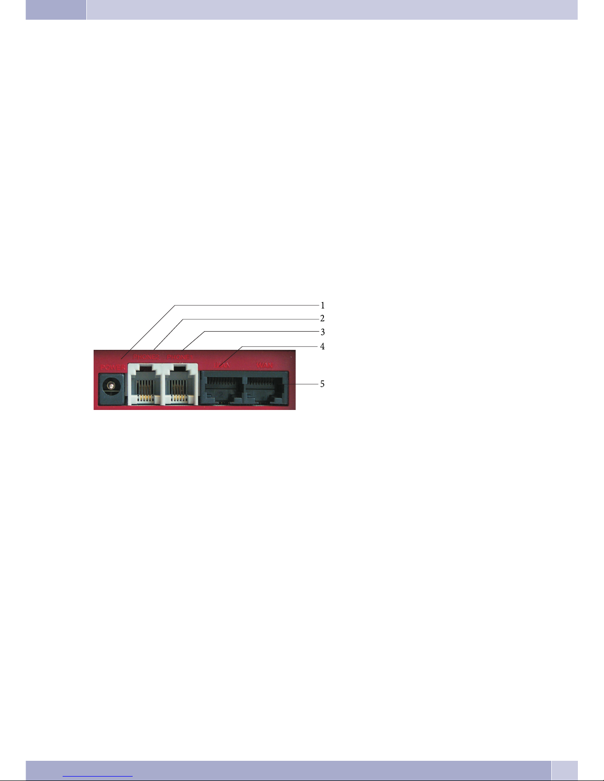
to the Internet and has two analog telephone sets attached, it supports two simultaneous VoIP calls. The V102 has Ethernet LAN and PC
ports for interfacing with ADSL and a notebook PC. Additionally, it features two RJ11 connectors for analog telephone sets (FXS). The two
FXS ports support T.38 functionality for telefax transmission through the Internet. Thanks to its integrated NAT/DHCP server the V102 is
also easily configured for various network scenarios using aWeb Browser on the PC or a telephone set, makingit the ideal tool for providers
(Internet Telephony Service-Providers) and SOHO users alike, who wish to make use of VoIP servicese.
Please note that the V102 requires one IP address, one subnet mask and one Gateway / Router IP address for connecting to the Internet.The-
se three items of information will be supplied to you by your Internet Service Provider. The V102 can activate PPPoE or DHCP functions in
order to have a dynamic IP address assigned automatically by the provider. Additional information can be found on page 9, (Configuration
through the Web Browser).
V102 SIP VoIP Telephony Adapter Features
The V102 TA offers the following features:
•SIP v1 (RFC 2543), v2 (RFC 3261) with MD5 Authentication (RFC 2069and RFC 2617).
•two RJ45 Ethernet ports and an RJ11 port for connection to analog terminal devices.
•ITU-T G.711, G.723, G.726, G.729A/B, VAD and CNG for Voice Codec.
•ITU-T G.165/168 Echo Compensation.
•Three LED Indicators: POWER, PHONE, LAN.
•Configuration supported through Web browser and telephone set.
•Integrated NAT/DHCP server.
•PPPoE/DHCP-Client für die dynamische Zuteilung der IP-Adresse, sowie NAT, DNS, und DDNS-Clients.
•Unterstützt STUN-Server für NAT-Traversal.
•Hot Line Mode support.
•Supports T.38 FAX via IP.
•Interactive voice response system (IVR) reads out IP status of phone.
•Remote Firmware Upgrade with HTTP or TFTP server through Web PC.
•Direkte IP/URL-Wahl ohne SIP-Proxy oder Rufnummer über SIP-Server.
•Telephony Features: Volume Adjustment, Phone Book, Speed Dialing, Call Forwarding, Call Waiting, Call Hold and
Three-Party Conferencing, Redialing, and Flash.
•Outband DTMF (RFC 2833) / Inband DTMF / DTMF-SIP-Info senden.
Compatibility t
The V102 VoIP TA supports the following standards:
VoIP Protocol: IETF RFC 3261 and RFC 2543 for SIP.
SIPAuthentication: IETF RFC 2069 and RFC 2617 for MD5.
Voicecodec: see page 22, as well as VAD (Voice Activity Detection) and CNG.
EchoCompensation: ITU-T G.165/168.
Package Contents
•V102 SIP VoIP Telephony Adapter.
•Power Supply Block 230V AC /12 VDC, 1 A .
•CD-ROM with User Manual.
•Brief description of functions.
•two RJ11 to TAE Adapters.
Bitte prüfen Sie, ob die Verpackung beschädigt ist oder ob ein Teil fehlt. If that is the case, please contact your dealer.
V102 SIP VoIP Telephony Adapter
4

LED Indicators and Connectors
On the front side of the V102 there are three LEDs:
POWER
Lit: The supply voltage has been applied.
PHONE:
Solid green light: The handset of phone 1 or phone 2 has been lifted up.
Flashing green light: SIP registration for phone 1 was successful.
Flashing red light: SIP registration for phone 2 was successful.
Flashing yellow light: SIP registration for phone 1 and phone 2 was successful.
LAN
Lit: The Ethernet LAN port is physically connected with a peer device.
Flashing: Data traffic on Ethernet LAN ports.
1-Power Supply
2-Phone port 2
3 - Phone port 1
4 - LAN port
5 - WAN port
Installation / SIP Configuration
•Use a Cat. 5 LAN cableto connect the »WAN« port of the TA to the ADSL modem or router.
•Use a Cat. 5 LAN cableto connect the »LAN« port of the TA to the LAN port of a notebook or desktop PC.
•Connect an analog phone to the »PHONE 1« port of the TA. If the phone isfitted with a (German standard) TAE con-
nector, insert the RJ11 to TAE adapter.
•Connect a second analog phone to the »PHONE2« port of the TA.
•Connect the power supply block. The »POWER« LED lights up.
•After approx. 5 seconds the »PHONE« LED flashes five times, then extinguishes as the unitgoes to VoIP configurati-
on mode. The LAN LED is permanently illuminated when the »WAN port« is connected.
•Lift up the handset on phone 1 or 2. The »PHONE« LED lights up, and you hear the dial tone. If you hear the busy
tone, please check whether the WAN port is correctly connected.
•On the phone dial #120# now in order to hear the TA’s factory-preset IP address read out loud to you.The preset IP
address is 192.168.123.001. Thisis the IP address you must enter in the Web browser in order to load the Web-based
configuration page. Please refer to page for further details about Web-based configuration.
•On page 30 you will find examples for VoIP applications involving SIP registration as well as for registering phones 1
and 2 with your SIP server.
•The PHONE LED flashes in green when phone 1 has successfully registered or in red when phone 2 has successfully
registered (yellow flashing indicates that both phones 1 and 2 have been registered successfully).
•After successful registration with the SIP server (see page Example 4) the »PHONE« LED flashes. Enter, for example,
the subscriber number 123456 in order to call the party registered in the SIP server with the subscriber number
123456. Approx. 5 seconds after dialing the last digit of the subscribernumber, you will hear the ringing tone. Alter-
natively you can press the # key after dialing the subscriber number to have dialing start immediately. When dialing
the subscriber number without the # key,dialing will not start before the autodial timer expires (preset to 5 seconds).
V102 SIP VoIP Telephony Adapter
5

Using Attached Analog Terminal Equipment
Not all of the service features described in the following are supported by all providers. If in doubt, consult with your provider to find out
which service features are included in your access service package and which ones need to be ordered separately.
Symbols
Please note: Different terminal devices will not necessarily have the same dial tones, ringing signals or procedures for use.
For further information on tone frequency and length, please refer to the assembly instructions.
Symbol Reference
Lift up the handset of your telephone.
This symbol indicates the call status. Youhave lifted up the handset of your telephone.
This symbol prompts you to hang up or indicates that the telephone is idle.
LThis symbol indicates some kind of signalingactivity at your terminal,for example, that your phone is ringing.
TThis symbol prompts you to dial the desired number.
1x0
*#
One of these symbols indicates that you should dial the digit shown, or a specificcharacter.
=x)
~
These symbols indicate a selection of digits or characters from which you canchoose the appropriate one.
RThis symbol prompts you to press the flash key (signal key).
qThis symbol indicates that an acknowledgement signal can be heard inthe handset.
dThis symbol indicates that a conference call is inprogress.
Telephony
Some terminal devices use their own special procedures for the functions described in the following. Refer to the operating instructions for
the terminal device being used for detailed information.
When subscribers are put on hold they hear waiting music, depending on the provider.
Making External Calls
bT #
Lift up handset Dial number Wahl mit der Raute been-
den
Conduct your call Terminate your call
A call between two internal analog extensions is an outgoing local call if the connection is made through your
provider.
Speed Dialing from the Phone Book
bt#lg
Lift up handset Dial the desired speed dial
destination (0...9)
Terminate dialing by pres-
sing the # key.
Subscriber is being called Conversation
Accepting Calls
lbga
Telephone is rin-
ging
Lift up handset Conversation Terminate your call
Using Attached Analog Terminal Equipment
6

Hot Line Calling
Making telephone calls with Direct Calling activated
bt
Lift up handset Begin dialing within the configured
time
Room Inquiry
gR
You are conducting a call.
You would like to call another party
Press the Recall flash button.
You hear the dial tone from the earpiece. The other party hears waiting music. They cannot
hear you.
Inquiry Call
You can call another party at any time during an ongoing call.
g R tg R
You are conducting a call.
You would like to call
another party
Press the Recall flash button.
You hear the dial tone from the
earpiece.
Dial the number of the party you
wish to call. Speak to the desired
party.
If you replace the handset, you
will receive a recall from the origi-
nal caller.
Accepting a Waiting Call (Inquiry Call to Waiting Party)
gR
You are conducting a call.
A second party calls you. You
hear the call waiting signal.
Press the Recall flash button. You will be connected with the waiting party now.
Your first call is put on hold (see »Inquiry call«). For
further procedures refer also to »Broker’s call«.
Enable Call Waiting
g #138# q
Lift up handset Dial this code
Disable Call Waiting
g #139# q
Lift up handset Dial this code
Broker’s Call
g R tg g
You are in a call but
wish to speak to a
third party.
Press the Recall flash button. Speak to that party.The original call
is put on hold
You are conducting the call.
The second call is put on hold.
RPress the R key in order to return to the original call, putting the second call on hold. By pressing the R key you can switch
back and forth between both parties.
If you switch back and forth between two external parties (broker’s call), then hang up your handset, the current call
is terminated and the caller on hold will call you by way of a »Recall«.
Three-Party Conferencing
gRtg
You are conducting a call with one
party and wish to include a third
party in the call.
Press the Recall flash button. Dial the number of the
party you wish to call.
You would like to include this
party in the first call.
RPress the Recall flash button. Conduct your three-party conference call.
dd
Using Attached Analog Terminal Equipment
7

The conference is ended when you hang up your handset. A party included in the conference call can hang up at any time and the party who
initiated the call can then continue the conference with the remaining callers.
If you are in a conference call and you hang up, your call is terminated and the two parties from your conference remain connected with each
other!
All settings for analog phones apply to both phones alike (exception: TA V101 »Service Domain Settings«).
Resetting the TA
The TA can be reset through any attached phone. Resetting deletes any data except for the content of the Phone Book. The entries from the
Phone Book are removed only when resetting is done through the Web Configuration page. (»Default Settings«).
g #198# q
Lift up handset Dial this code
The TA will revert to the factory preset configuration and go to »POWER-ON« cycle. After four seconds the »PHONE« LED flashes five ti-
mes, then extinguishes. The »POWER« LED lights up.
Using Attached Analog Terminal Equipment
8

Configuration through the Web Browser (V101, V102)
You can configure the TA with a Web browser. To get started, first enter the IP address on the Web page.
•The factory-preset IP address is http://192.168.123.1.
•The following Web page will appear on your PC.
Enter the User Name and Password in the empty text boxes provided for that purpose. The preset values are:
•User Name: root
•Password: test
Click the «Login« button to go to the Management Information page for the system setup.
Please note: Whenever you change a setup on a Web page, be sure to click the page’s »Submit«button followed by the
»Save« button in order to have the new setup saved to non-volatile memory and activated.
System Information
The »System Information« page displays technical information like »Model Name«, »Firmware Version« and »Codec Version«.
Under »Model Name« you will find the name of the TA. In this field, »VoIP TA« identifies the V101 SIP VoIP telephony adapter and »VoIP
FXS/FXS TA« is for the V102 SIP VoIP telephony adapter.
•Click the desired menu item at the left border in order to configure the TA.
Configuration through the Web Browser (V101, V102)
9

Phone Book
Phone Book / Speed Dial Settings
The »Phone Book« menu item lets you set up the Speed Dial feature under »Speed Dial Settings« and the Direct Call feature under »Hot Line
Settings«. You can add, change or delete speed dial numbers in the speed dial list ( »Speed Dial Phone List«).
Entering a Speed Dial Destination
Under »Add New Phone« you can enter a new speed dial destination.
•Under »Position« you may choose one out of 10 speed dial destinations (0...9). The digits 0 through 9 each represent
a subscriber number. The TA dials these destination numbers automatically whenever you enter the appropriate di-
git for the desired subscriber.
•Under »Name« you can enter a name for each speed dial destination.
•Under »URL« you enter either the phone number, the URL,or the IP address of the subscriber you wish to store un-
der this speed dial destination.
•When you are done, click the »Add Phone« button.
•By clicking the »Reset« button you can delete the entries made under »Add New Phone«.
Once an entry has been added to the »Speed Dial Phone List« you cannot edit it anymore.
Removing a Speed Dial Destination
•Go to the »Select« column, choose the entries you want to remove, and click the »Delete Selected« button.
•If you wish to remove all subscriber numbers in one go, you need not choose all entries in the »Select« column. Sim-
ply click the »Delete All« button instead.
Direct Call (Hotline Setting)
If you lift up the handset of the phone but do not start dialing within the specified »Waiting Time« (factory preset to one second), a user-se-
lected subscriber number will be dialed automatically.
Programming Direct Call Mode
•Under »Hot Line Setting« choose »On« in order to enable the Direct Call feature.
Configuration through the Web Browser (V101, V102)
10

•Under »Hotline No.« enter the Direct Call destination.
•Under »Name« you can enter a name for the direct call destination.
•Under »URL« enter either the phone number, the phone number in URL format, or the IP address of the subscriber
you wish to reach under the direct call number.
•Under »Waiting Time« enter the desired delay between the moment when you lift up the handset and the time when
direct calling kicks in.
•Confirm your entries by clicking the »Submit« button.
Call Settings
The »Call Settings« menu item lets you access the following eight submenus:
•Call Forward
•SNTP
•Volume Settings
•Block Settings
•Caller Identification
•Autodial Timer (Dial Plan Setting)
•Flash Key (Flash Time Setting)
•Call Waiting
•T.38 FAX Setting
Call Forward
This feature lets you redirect your phone calls and incoming telefax messages to a location of your choice.For example, you wish to have a te-
lefax message addressed to your office also sent to your fax machine at home.
Please note that not all providers support call forwarding. Before setting up this feature, you should therefore ask
your provider for advice.
On the page »Forward Setting« you can select the forwarding mode, then enter the destination URL (phone number, phone number inURL
format or IP address) to which incoming calls should be forwarded, as well as a name. The following call forwarding options are available:
Call forwarding on
No Answer
Forward):
An incoming call will be forwarded to the specified phone number, phone number in URL format, or
IP address if the called subscriber does not pick up the handset within a specified time (as entered in
»Time Out«).
Configuration through the Web Browser (V101, V102)
11

Set Up Call Forwarding
You may enable all three call forwarding modes at the same time. In this case the TA will only use »Call Forward Unconditional« (All For-
ward). This call forwarding mode has the highest priority. The two remaining call forwarding modes may be active concurrently.
•To enable the desired call forwarding mode, choose »On«.
•Under »All Fwd No.:«, »Busy Fwd No.:« or »No Answer Fwd No.:« you can use the »Name« text box to enter a name
for the forwarding destination.
•Under »URL« you enter either the phone number, the phone numberin URL format or the IP address of the subscri-
ber to whom calls should be forwarded.
•Under »No Answer Fwd Time Out« you specify the number of calls after which Call Forwarding on No Answer
should kick in and redirect calls to the specified destination. You can choose any number between 2 and 8 ringing
tones (»2~8 Ring«).
•Confirm your entries by clicking the »Submit« button.
Time Synchronization Setup (SNTP Settings)
To ensure that your TA is synchronized with standard network time, it is recommended to choose a time server. This server may be installed
at an external location on the Internet as a so-called Public Time Server or reside in your own network. If you have configured a computer
within your network as a Time Server, enter the IP address of that computer here.
SNTP
•To enable time synchronization choose »On«.
Time Synchronization
(Time Server)
•Under the »Primary Server« and »Secondary Server« setup items, enter the IP addresses of the »time synchronizati-
on sources«. You can enter two different addresses to ensure that time synchronization remains active off an alter-
native server when the primary server goes down.
Time Zone
(Time Zone)
•Here, enter the time difference between the standard time »Greenwich (Mean) Time« and your own location. For
Central Europe the time zone needs to be set to + one hour (+ 01:00). Please note that Daylight Saving Time may be
in force when setting the time zone.
Synchronization Time
(Sync. Time)
•Use this option to specify at which time interval (»Sync. Time«) resynchronization with the time server should take
place.
•Confirm your entries by clicking the »Submit« button.
Configuration through the Web Browser (V101, V102)
12

Volume Settings
•This option lets you set the volumes for voice communication.What you set here are the signal levels delivered to
and received from the analog terminal.
Handset Volume
•Here you can enter the signal level that drives the volume in the speaker of the handset of your terminal.
Handset Gain
•Here you can enter the gain by which the volume received through the microphone of your phone set shall be raised.
•Confirm your entries by clicking the »Submit« button.
Please note that these settings are independent of any volume settings on your analog phone.
Block Settings
On this page you can set up the »Blocking« feature. Choose whether the phone should not ring at all (by setting »Always Block« to »On«) or
whether ringing should be blocked for a certain period of time (»Block Period«).
No Ringing (Always Block)
Incoming calls will not ring your phone until you deactivate this function.
•To enable »Blocking« (Always Block) choose »On«.
Block Period
•The “SNTP Settings” must be properly set to be able to use this feature. To enable »Blocking« for a certain period of
time, choose »On« for the » Block Period« option.
•In the »From« and »To« text boxes enter the start and end times of the period during which ringing should be sup-
pressed. If the time of day specified for »From« occurs later than the one specified for »To«, ringing will be suppres-
sed until that time on the following day.
•Confirm your entries by clicking the »Submit« button.
Please note that this feature requires an SNTP server.
Configuration through the Web Browser (V101, V102)
13

Caller ID Setting
On the »Caller ID Setting« page you can set how callers are identified on the display of your phones.
Consult the User Manual of your phone which subscriber number signaling mode must be preset in the TA in order to
accommodate the device.
Please note that the necessary settings are provider-specifc.
Number Signaling Format
Depending on the type of terminal in use you must choose the appropriate format. Consult the User Manual of your phone to find out which
number signaling format it supports.
You can choose between the following number signaling formats:
Don’t show caller ID
•If your attached analog phone does not support caller identification or if you do not wish to have the caller’s name
and or number displayed, choose this menu option.
Caller ID after 1st Ring (FSK)
This setup is currently applicable for the following countries:
•Germany.
Caller ID before 1st Ring (FSK)
This setup is currently applicable for the following countries:
•
Caller ID before 1st Ring (DTMF)
For example, this setup is currently applicable for the following countries:
•Denmark.
Do Not Show Name (Single Caller ID)
If your provider supports the identification of the calling party’s number and name and your phone is able to understand that signaling in-
formation, you can view the name and number information on your display. Select »No« if this is desired. If you wish to have your phone
display only the number but not the name, choose »Yes«.
CID Without Time
•If your provider does not support this function, choose »Yes«.
•Confirm your entries by clicking the »Submit« button.
These settings apply to both attached analog phones.
Configuration through the Web Browser (V101, V102)
14

Dial Plan Setting
If you have enabled this service feature by choosing »ON«, the TA may recognize specific subscriber numbers or sequences of digits and pro-
cess them in the following ways:
•Replace Rule
•Dial Plan
•Auto Prefix
•Prefix Unset Plan
•Auto Dial Time
Replacing Numbers (Replace rule)
By setting a »Replace Rule« you can have the TA replace a specificnumber you dial, for example, by a prefix and the same subscribernumber.
The replaced subscriber number may be 7 digits long at maximum.
Enter Representing
x or X 0,1,2,3,4,5,6,7,8,9
+or
Example:
Replace rule 001+006+009 -> 005
The sequence 001 or 006 or 009 is replaced with 005.
Dial Plan
The TA is able to detect a specific number and dial that number immediately without waiting for the # key that delimits the dialed sequence.
Certain numbers, such as the emergency services number, are dialed immediately after the caller has entered the specific sequence of digits
(example: emergency telephone number 999 used in the U.K.). The following entries are supported to enable the detection of numbers:
*xx Immediately dials specific two-digit function code numbers (for example PABXsystem control codes) if preceded by the
asterisk (*) key.
#xx Immediately dials specific two-digit function code numbers (for example PABXsystem control codes) if preceded by the
number(#) key.
10x Immediately dials specific telephone numbers (for example emergency service numbers) if the dialed number has three
digits and starts with »10«.
11x Immediately dials specific telephone numbers (for example emergency service numbers) if the dialed number has three
digits and starts with »11«.
XXXXXxxx Immediatelydialsspecifictelephonenumbers(forexampleanynumberhavingthesamedigitcount)ifthedialednumber
has as many digits as specified in the »x« sequence.
Example
Speed dial *xx+#xx+10x+11x+Xxxxxxxx
Example explained:
Enter Does What
*xx Recognizes digits / sequences with: *00, *01, …,*99
#xx Recognizes digits / sequences with: #00, #01, …,#99
10x Recognizes sequences with: 100,101, …,109
11x Recognizes sequences with: 110,111, …,119
Xxxxxxxx Recognizes a-digit sequences
Auto Prefix
You may, for example, have the TA automatically place the country code or local area code before a telephone number you dial. For this to
work, enter the desired telephone number under »Auto Prefix«.
Configuration through the Web Browser (V101, V102)
15

Example:
Auto Prefix 0049 (00000000~99999999)
Prefix Unset Plan
This function instructs the TA not to place the prefix specified under »Auto Prefix« before a subscriber number of your choice.
For this to work, the following conditions must be fulfilled:
•The TA must find a certain first digit in the number you dial.
or
•The TA must find a certain number of digits in the number you dial.
Example:
Prefix Unset Plan 0+9+xxxx+xxxxxx
Example explained:
Enter Does What
0 If the first digit is set to »0«, as in the example below, no prefix is placed before any number that starts
with a »0«. This is the case if you dial a number with a prefix (for example 05171 1234567). This num-
ber is sent out exactly as you enter it.
+ This character means »or«. It allows you to combine several unset patterns, as shown in the example
below.
9 If the first digit is a »9«, as shown in the example below, no prefix is placed before any number that
starts with a »9«. This is the case if you dial a subscriber number like, for example, 9234567. This num-
ber is sent out exactly as you enter it.
+Or
xxxx Numbers made up of any combination of four digits are sent out exactly as entered, for example 1234.
+Or
xXxXxX Numbers made up of any combination of six digits are sent out exactly as entered, for example 123456.
You can add more entries here, separated by a »+« character.
•Confirm your entries by clicking the »Submit« button.
Auto Dial Time
If you enter digits for composing a subscriber number, the TA must have some means of recognizing when dialing ends. During manual dia-
ling, you mark out the end of a dialed number by pressing the number (#) key. If you do not press the number (#) key dialing is considered as
completed when a certain period of time (»Auto Dial Time«) has elapsed after the last digit. You can adjust the length of that period of time
between 3 and 9 seconds.
Configuration through the Web Browser (V101, V102)
16
Other manuals for V101
1
This manual suits for next models
1
Table of contents
Other Funkwerk Telephone Accessories manuals