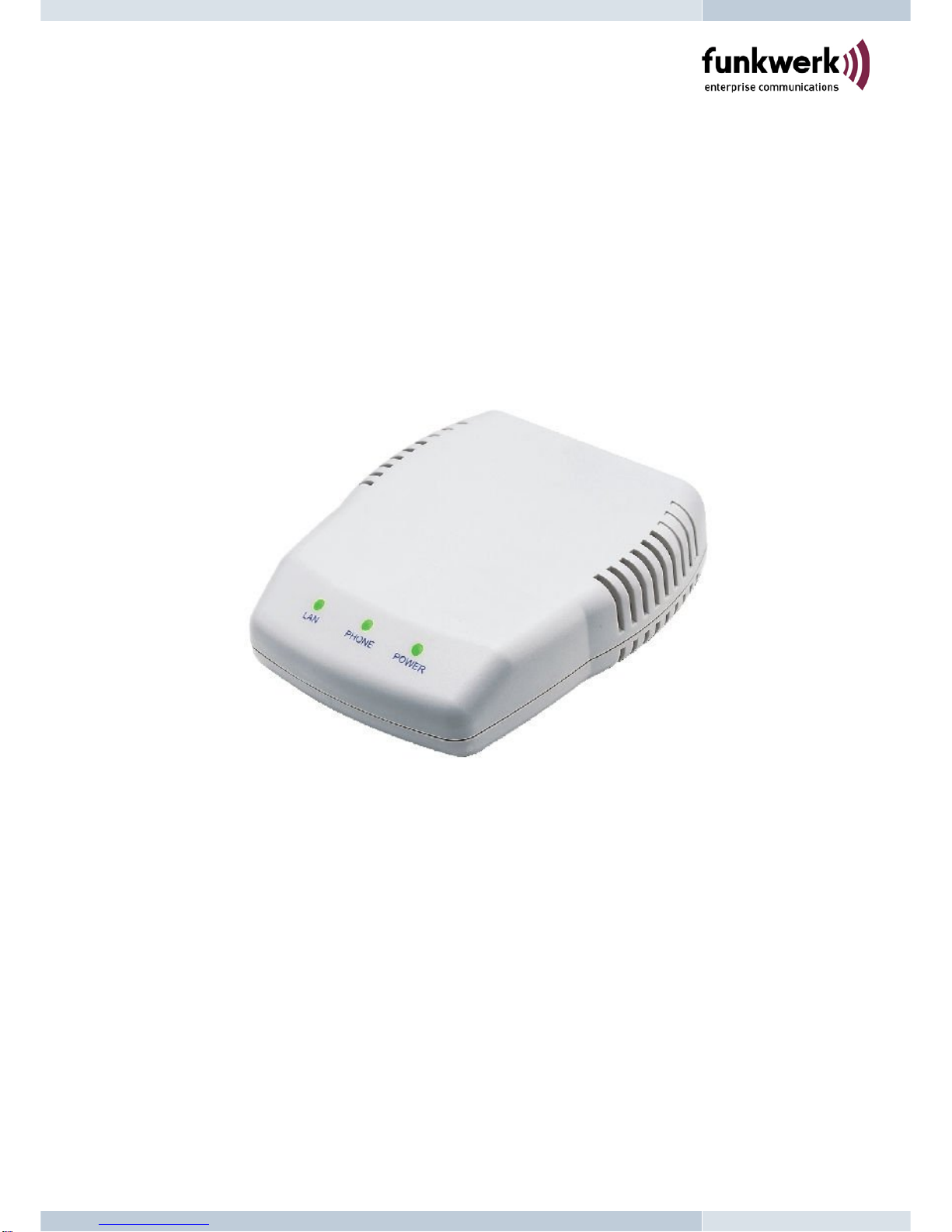
Funkwerk V102 User manual

V102
2-Port SIP VoIP Telephone Adaptor
User Manual
V1.10

Quick Guide
Step 1: Broadband (ADSL/Cable Modem) Connections for V102
A. Connect V102 LAN port to ADSL modem as the following connection.
B. Connect V102 PC port to Notebook PC LAN port using a Category 5 LAN cable.
C. Connect V102 RJ11 PHONE1 port to one analog telephone set.
D. Connect V102 RJ11 PHONE2 port to another analog telephone set.
E. Connect Power Adaptor. After power on, the POWER LED will be Green ON.
F. Pick up Phone1 or Phone 2, and the PHONE LED will be Green ON indicating Off-Hook.
G. When the PHONE LED is Green flashing, it indicats a successful SIP registration for Phone
1.
H. When the PHONE LED is Red flashing, it indicats a successful SIP registration for Phone
2.
I. Press #121# and #120# from the phone to listen to IVR and to check the DHCP status and
the IP address (e.g. 192.168.1.100) for V102. After the IP announcement, please hang up.
Figure A. ADSL Connections with NAT Router for V102
Step 2: Settings for V102 from PC Web Browser
A. This is an example for FWD ITSP provider using ADSL connection with NAT router as in
Figure A. Both parties sign up to FWD SIP server http://www.freeworlddialup.com with
registered FWD phone number and password.
B. Pick up the phone and press #120# from the phone to listen to IVR and get the IP address
(e.g. 192.168.1.100) for V102.
C. Enter the IP address from PC Web browser for configuration settings.
Example:Enter http://192.168.1.100 from IE Web browser to display login page.
D. Enter the user name and password into the blank field. The default settings are Username:
root Password: test . Click the “Login” button to enter for configurations.
i
PC PHONE1
NAT Router
ADSL Modem
Router IP: 192.168.1.254
V102 IP: 192.168.1.100 L
A
N
PC IP: 192.168.1.101
PHONE2
INTERNET

E. You need to set up the following web configurations: Network Settings, SIP Settings, NAT
Settings/STUN Settings. Remember to submit, save and reboot for new configurations.
F. The PHONE LED will be Green flashing showing a successful registration in the SIP
server. For further detail configurations, please refer the VoIP applications in the user
manual.
Step 4: Making Point-To-Point SIP Calls
A. Pick up the phone and you should hear a dial tone.
B. Press 123456# to call the party with the number 123456 registered in the SIP server. Note
#is used to send out the call immediately. In a moment, you should hear the ring back tone,
and wait for the called party to answer. For more applications, please refer to the user
manual.
Note: If you have difficulties in configuring V102, please refer to the last chapter for trouble
shootings.
ii

TABLE OF CONTENTS
1.Introductions………………………………………………………………
2.Features ………………………………………………………………………
3.Packing Contents ……………………………………………………
4.LED Indicators……………………………………………………………
5.Installations & SIP Configurations ……………………
6.Default Reset from Telephone ……………………………
7.Configurations from Web Browser ……………………
8.Configurations from Telephone & IVR………………
9.VoIP Applications Examples…………………………………
SIP-to-SIP Calling/Answering ……………………………
SIP to Direct IP Calling …………………………………………
Direct IP to Direct IP Calling/Answering ………
Direct IP to Direct IP Calling within NAT…………
3-Way Conference Call, Call Waiting, Hold……
SIP-to-SIP Calling for FWD …………………………………
10.Advanced Settings for Embedded NAT …………
11.Trouble Shooting for Web Configurations ……
1
1
2
2
3
3
4
27
28
29
29
30
30
31
32
35
38

1. Introduction
The V102 is a 2-port FXS Telephone Adaptor (TA) with SIP Protocols for Voice over IP (VoIP)
applications. Connecting to the Internet and two analog telephone sets, the V102 can
supports two concurrent VoIP calls over the Internet. V102 provides Ethernet LAN and PC
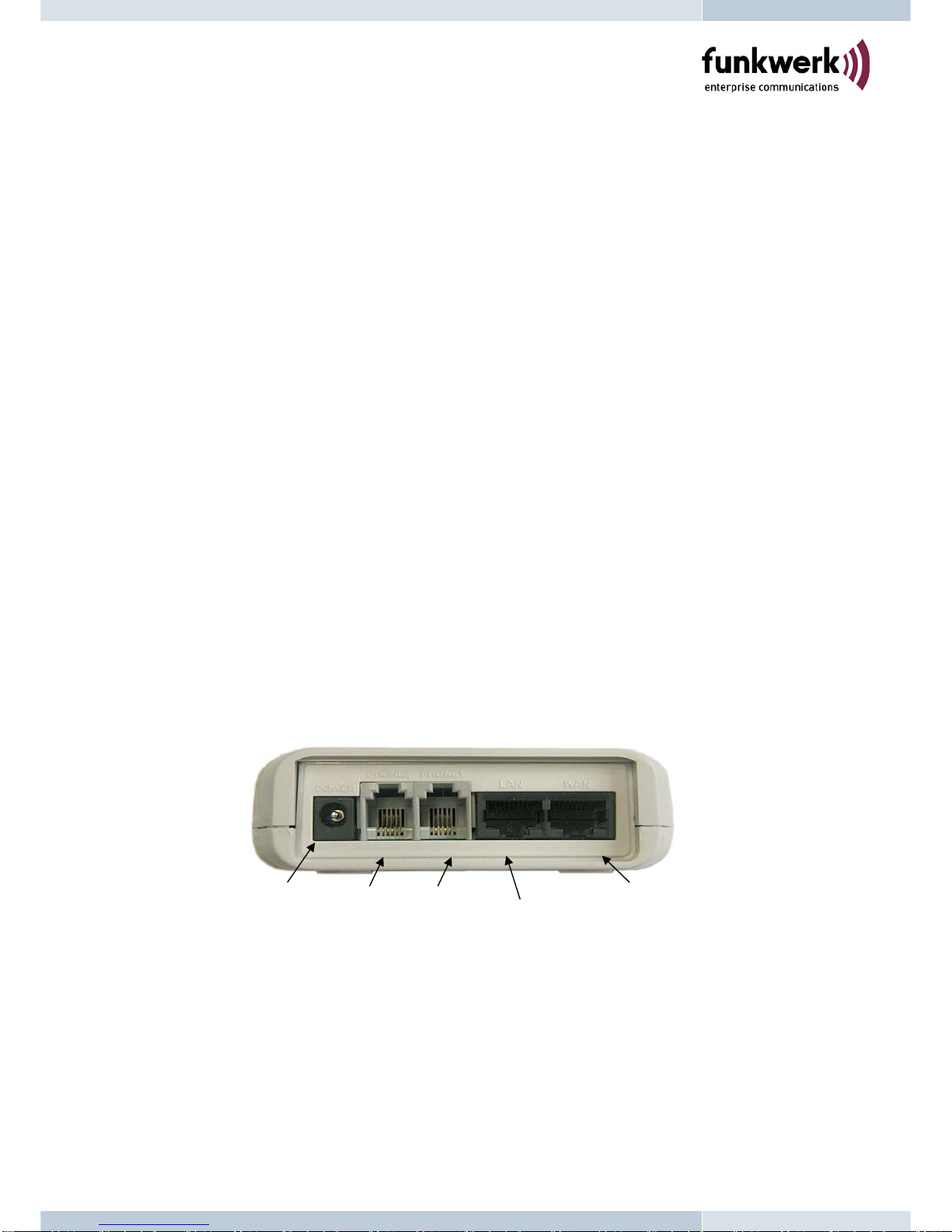
ports for ADSL and Notebook PC connections. It also provides two RJ11 connectors for
analog telephones (FXS). The two FXS ports can support T.38 features for FAX over
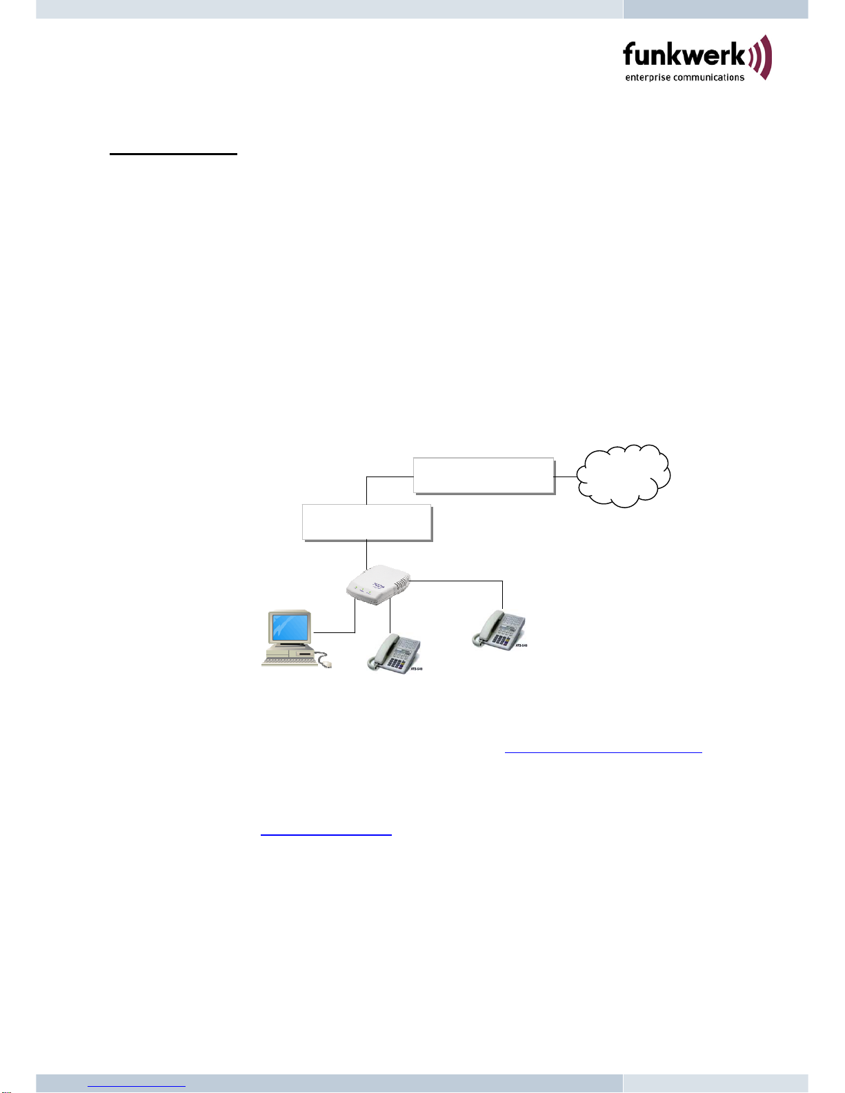
Internet. With an embedded NAT/DHCP server, V102 can be easily configured to fit for
different network diagrams by PC Web browser and telephone set, and it is very suitable for
ITSP (Internet Telephony Service Providers) and SOHO users to make VoIP calls.
Note that V102 requires an IP address, a subnet mask, and its gateway Router IP address for
its own use to connect to Internet. These three are available from your Internet service
provider. V102 may enable PPPoE or DHCP features to automatically get an assigned
dynamic IP from the ITSP. Please refer to Section 7 Configurations from Web browser for
detailed information.
2.Features
The V102 VoIP TA is equipped with two RJ11 connectors and two RJ45 connectors and is
featuring as the following
¾SIP v1 (RFC2543), v2 (RFC3261) with MD5 authentication (RFC2069 and RFC 2617)
¾RJ45 x 2 for Ethernet + RJ11 x 2 for FXS ports
¾ITU-T G.711, G.723, G.726, G.729A/B, VAD and CNG for Speech Codec
¾ITU-T G.165/168 Echo Cancellation
¾Three LED Indicators for V102: POWER, PHONE, LAN
¾Configurations by Web Browser and Telephone
¾Embedded NAT/DHCP Server
¾PPPoE/DHCP Client for Dynamic IP plus NAT, DNS, and DDNS Clients
¾Support STUN server for NAT Traversal
¾Interactive Voice Recording (IVR) for telephone IP status
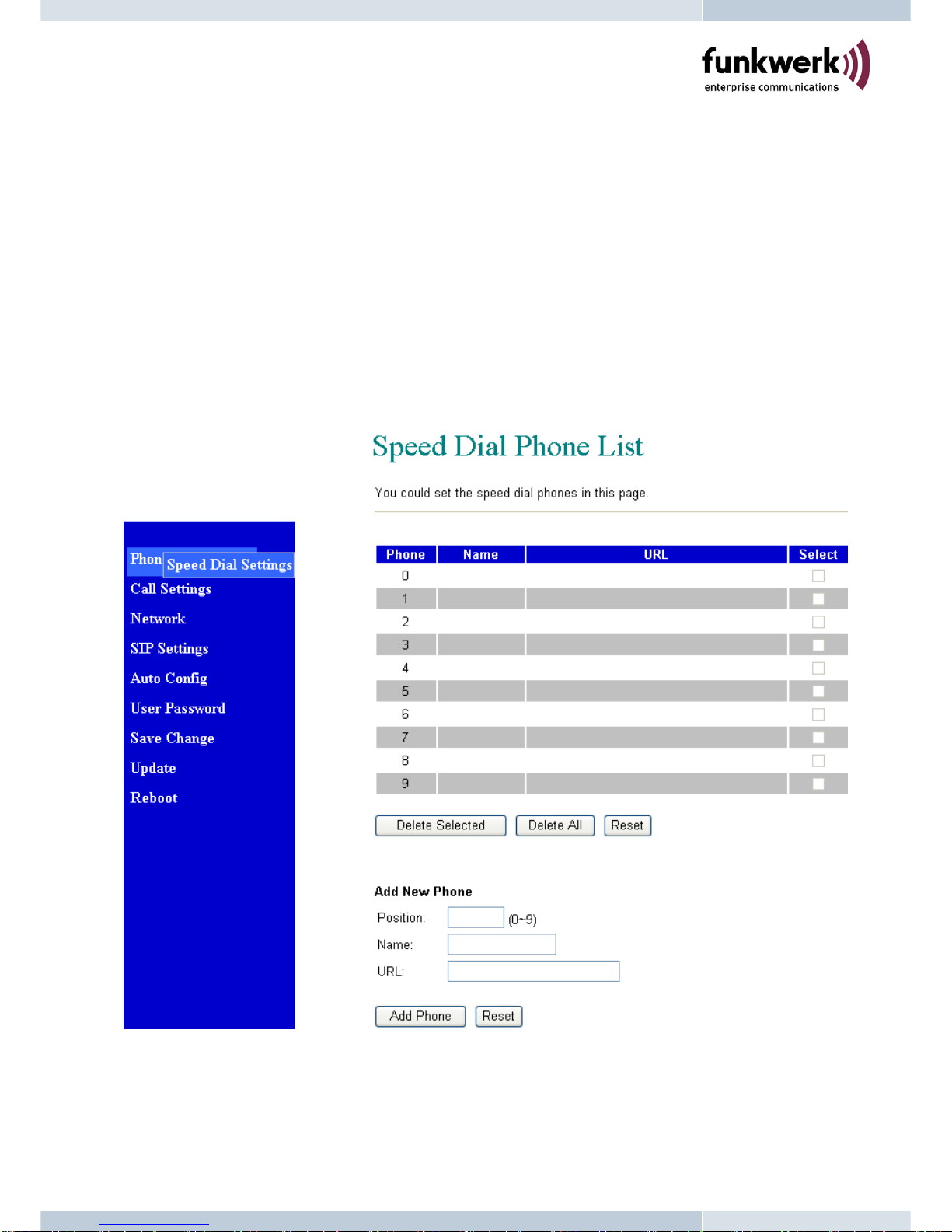
¾Speed Dial, Call Forward/Waiting/Transfer/Hold, and 3-Way Conference Call features
¾Remote Firmware Upgraded with HTTP or TFTP server by Web PC
¾Direct IP/URL Dial without SIP Proxy or Dial number via SIP server
¾Telephone features: Volume Adjustment, Phone book, Speed Dial, Redial, and Flash
¾Out-Band DTMF (RFC 2833) / In-Band DTMF / Send DTMF SIP Info
1

3. Packing Contents
Inside the package you should find:
(1) One V102 2-Port SIP TA
(2) One AC to 12VDC/1A Power Adaptor
(3) One User Manual CD
Please check if the packing is damaged or any component is missing. If so, please
contact your distributor.
4. LED Indicators
On the front panel of V102, there are three LED indicators as the following
POWER: “On” indicates the power is normal
PHONE: “Green On” indicates Off-Hook on Phone 1 or Phone 2.
“Green Flashing” indicates a successful SIP registration for Phone 1.
“Red Flashing” indicates a successful SIP registration for Phone 2.
“Yellow Flashing” indicates successful SIP registrations for both Phone 1 & 2.
LAN: “On” indicates the Ethernet Ports are in Connection.
“Flashing” indicates the data activity of Ethernet ports.
2
Power Phone 2 LAN WAN
Phone 1

5. Installations & SIP Configurations
1. Connect V102 RJ45 LAN port to ADSL Modem using a Category 5 LAN cable.
2. Connect V102 RJ45 PC port to Notebook PC using a Category 5 LAN cable.
3. Connect V102 RJ11 PHONE1 port (next to PC port) to a Plain Old Telephone Set
(POTS).
4. Connect V102 RJ11 PHONE2 port to another Plain Old Telephone Set (POTS).
5. Connect the power adaptor (12VDC) to power on V102, and the POWER LED will be ON.
6. The PHONE LED indicators will be OFF for about 5 seconds and start flashing for 5
times, and remain OFF for VoIP configurations. The LAN LED will be ON when RJ45
WAN ports is connected. Pick up Phone1 or Phone 2, and the PHONE LED will be
Green ON indicating Off-Hook. If you hear a busy tone, please check if the WAN port is
connected.
7. Press #120# from Phone to check the assigned IP address for the V102. The default IP
address is 192.168.1.100. Please refer to Chapter 7, and you may enter this IP address
in IE Web browser for web configurations.
8. Please refer Chapter 9 for VoIP applications examples of SIP registrations, and register
Phone 1 & 2 into your SIP server.
9. The PHONE LED will be Green flashing for Phone 1 successful registration, and Red
flashing for Phone 2 successful registration, respectively. (Yellow flashing for both Phone
1 & 2 successful registrations.)
10. After successful registration into the SIP server, the PHONE LED will be Green flashing.
Pick up the Phone 1, and you should hear a dial tone. Press 123456# to call the party with the
number 123456 registered in the SIP server. Note that #will dial out the number
immediately. Dialing without # will not dial out until the auto dial timer (default=5 seconds)
elapsed. In a moment, you should hear a ring back tone, and wait for answer.
6. Default Reset from Telephone
V102 provides an easy way to reset to factory defaults by using Telephone.
Pick up the phone and press #198# to reset back to factory defaults, and the V102 will enter
into POWER ON cycle. The PHONE LED indicators will be OFF for about 4 seconds and
start flashing for 5 times. The POWER LED then will be lit constantly, and the PHONE LED
will be OFF.
3

7. Configurations from Web Browser
You may enter the IP address from PC Web browser to configure V102. For example, enter
http://192.168.1.100 from IE web browser to display login page as follows.
7.1. Please enter the username and password into the blank field. The default settings are:
Username: root
Password: test
7.2. Click the “Login” button will enter the management information page for system setup.
Note that whenever you change the setting in each Web page, please remember to click the
“Submit” button in the page, and click the “Save” button to save into the non-volatile memory
and click the “Reboot” button to activate the new settings.
4

System Information
7.3. You will see the system information like firmware version, Codec, etc in this page.
7.4. You may click the button list at the left hand side to configure the V102.
5

Phone Book for Speed Dial
7.5. The Phone Book page specifies Speed Dial function.
7.6. For Speed Dial function you can add/delete Speed Dial number up to maximum 10 entries
in Speed Dial Phone List.
7.7. If you need to add a phone number into the Speed Dial list, you need to enter the
position, the name, and the phone number (by URL type). When you finished a new
phone list, just click the “Add Phone” button.
7.8. If you want to delete a phone number, please select the phone number you want to delete
then click “Delete Selected” button.
7.9. If you want to delete all phone numbers, please click “DeleteAll” button.
7.10. Example: Press 2# on telephone to Speed Dial the phone number 2immediately.
6

Call Settings
7.11. The subpages are as follows; Call Forward, SNTP, Volume, Block Settings, Caller ID,
Auto-Dial Timer, Flash Time (or hook switch), Call Waiting, and T.38 FAX functions.
Call Forward function:
7.12. You can select the forward mode and enter the forward URL.
All Forward: All incoming call will forward to the URL you choose.
Busy Forward: The incoming call will forward to the URL when the callee is busy.
No Answer Forward: The incoming call will forward to the URL when no answer.
Note you have to set the Time Out timer for system to start to forward the call to the
number you choosed. When you finish the setting, please click the “Submit” button.
7

SNTP Setting:
7.13. You can setup the primary and second SNTP Server IP Address, to get the date/time
information. You may also set the Time Zone, and how long need to synchronize again.
When you finish the setting, please click the “Submit” button.
8

Volume Setting:
7.14. You can setup the Handset Volume, Ringer Volume, and the Handset Gain in this page.
When you finish the setting, please click the “Submit” button. Handset Volume is to set
the volume to hear from the handset. Ringer Volume is to set the ringer volume. Handset
Gain is to set the volume send out to the other side’s handset.
Block Setting:
7.15. You can setup the Block Setting to keep the phone silence. You can choose either Always
Block or a Block period.
7.16. Always Block: All incoming call will be blocked until this feature is disabled.
7.17. Block Period: Set a time period and the phone will be blocked during the time period. If
the time in “From” is greater than that in “To” time, the Block time will be from Day 1 to
Day 2.
7.18. After you finish the setting, please click the “Submit” button.
9

Caller ID Setting:
7.19. You may show caller ID in your PSTN Phone or IP Phone by selecting “Yes” in Single
Caller ID, and the desired Caller ID option for either FSK or DTMF. When you finish the
setting, please click the “Submit” button.
Auto Dial Setting:
7.20. You can set the timer for inter dial digit in this page. When the timer expires after finished
dialing, V102 will dial out the call automatically. When you finish the setting, please click
the “Submit” button.
10

Flash Time Setting:
7.21. You can set the flash time duration for the telephone flash key or hook switch in this page.
The telephone flash key is used to switch to the other phone line or HOLD, and is quite
useful for the 3-way conference call and the call waiting function. When you finish the
setting, please click the “Submit” button.
Call Waiting Setting:
7.22. You can enable the call waiting function in this page. It allows answering another coming
call by pressing flash key while holding the current call. You may switch back to previous
call by pressing flash key again. When you finish the setting, please click the “Submit”
button.
11

T.38 (FAX) Setting:
7.23. The T.38 FAX over IP function allows FAX machine to communicate with another FAX
machine over IP network. The defaults are OFF for Phone1 and Phone2. The T.38 ports
of Phone1 and Phone2 must be differents. When you finish the setting, please click the
“Submit” button.
12

Network
7.24. You may configure the Bridge, NAT, and DDNS settings to show the Network status in this
section. If you have an external NAT router, then you must select Bridge ON in the Bridge
settings to disable embedded NAT. In this case, the two Fast Ethernet ports will be
bridged and transparent. Otherwise, you must select Bridge OFF to enable embedded
NAT and go on NAT/DDNS settings. The network status will show either bridge mode or
NAT mode depending on the selection of Bridge ON/OFF. The default is Bridge ON.
Network Status:
7.25. You can check and show the current Network settings in this page.
13

Bridge Settings:
7.26. You can configure Bridge settings for V102 in this page.
7.27. The IP type for V102 is Fixed IP (192.168.1.100) at default. You may select a proper IP
type for your network requirements.
7.28. The Bridge mode can be ON/OFF. If you select the Bridge ON mode, then the two Fast
Ethernet ports will be bridged and transparent.
7.29. After you finish the setting, please click the “Submit” button.
14

NAT Settings:
7.30. When you select Bridge OFF, the embedded NAT will be enabled. This is useful for ADSL
users without NAT router.
7.31. Enable the embedded DHCP Server at the LAN setting to automatically obtain a private
IP address for PC from the embedded DHCP server.
7.32. You may select PPPoE function at the WAN setting, and enter the given username and
password for ADSL. Note that the MAC settings for LAN and WAN must be different from
each other.
7.33. After you finish the setting, please click the “Submit” button.
15

DDNS Setting:
7.34. You need to have a DDNS account before configuring the DDNS setting. Usually, most of
the VoIP applications are working with a SIP Proxy Server. Nonetheless, you may have a
DDNS account with a public IP address, and others can call you via the DDNS account.
When you finish the setting, please click the Submit button.
16
Table of contents
Other Funkwerk Telephone Accessories manuals