6
P-2400 IT OWNER’S MANUAL
small magnec eld. Therefore, we recommend that it not be posioned adjacent to sensive, low level signal processors, especially
mic preamps, mixers, tape recorders, etc. Power amps may be more suitable “rack neighbors.”
The maximum benet derived from balanced power is when it powers ALL equipment in an installaon. Therefore, try to posion
the P-2400 IT in a central locaon so its power can be easily distributed everywhere it’s needed. If the total power consumpon of
all equipment exceeds 20 amps at 120 volts, delete high level or mechanical devices rst (such as power amps, motors). If possible,
physically isolate any equipment that has to be powered with convenonal power through a dierent circuit, and route AC cords away
from all other cabling. The balanced power produced by the P-2400 IT is restricted to use with electronic equipment only. Balanced
power may not be used for lighng equipment, and access must be limited to use by qualied personnel only.
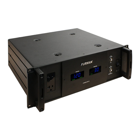
Rear Rack Mounng:
If you are installing the P-2400 IT in a rack that has rear as well as front mounng rails, you may easily secure it to the rear of your rack.
Simply remove the securing screws from the side and front porons of the P-2400 IT’s adjustable rear rack ear and reinforcement side
plate (located on either chassis side), reverse it and re-aach to the P-2400 IT chassis. (See Figure 1.a, page 12)
OPERATION
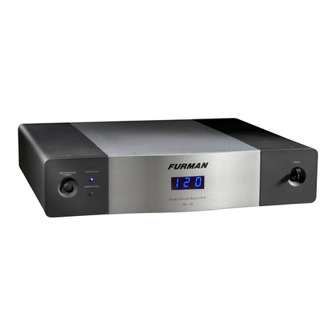
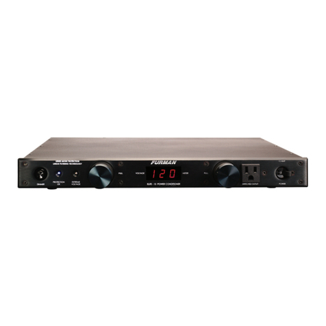
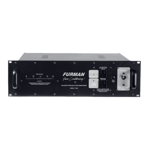
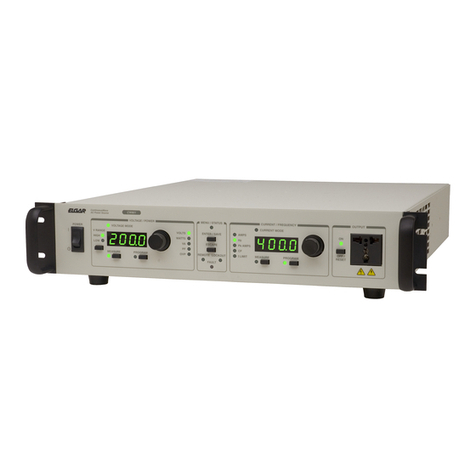
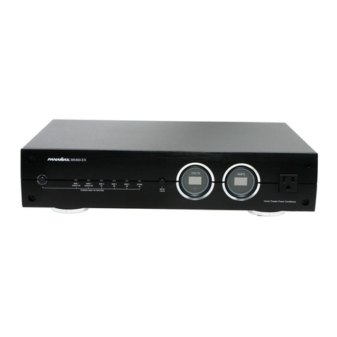
Switchable Voltage and True RMS Current Meter:
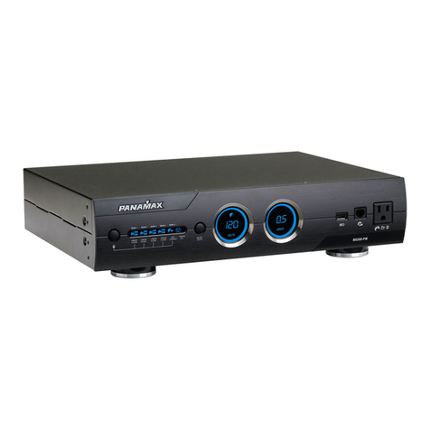
Furman’s laboratory precision AC digital voltmeter connually measures incoming voltages within a typical tolerance of +/-1.5VAC. It
should be noted that the voltage reading is incoming.
Furman’s laboratory precision True RMS digital current meter connually measures the total circuit AC load within a typical tolerance
of +/- 0.5 amp. Because these meters feature true RMS technology, the current readings are accurate regardless of load condions
(capacive, inducve, or resisve). To switch between voltage and current, press the buon labeled “Line Voltage/Current”. Hold this
buon down for two seconds to dim the brightness of the display.
Voltage Range Indicator:
This indicator is located in the lower le corner of the digital volt / amp meter lens assembly. When AC voltage is within 5 volts (+/-)
of a nominal 120VAC source, this tri-color indicator will be green (opmal). However, if the voltage is between 110 to 114VAC, or be-
tween 126 to 130VAC, the indicator will turn amber (cauon - not opmal). If the incoming voltage is in an extreme range (below 110
or above 130), the indicator will turn red. This range is far from opmal, and may be potenally damaging to some equipment.
Ground Fault Interrupter (GFCI):
The Ground Fault Circuit Interrupter (GFCI) on the P-2400 IT’s rear panel is a special kind of circuit breaker that detects an imbalance
in the current owing into the two hot legs. The “missing” current is presumed to be owing through the ground conductor (the round
pin on an AC outlet).
Ground current oen indicates a dangerous paral or full short circuit. If an imbalance is detected, the GFCI trips and cuts o power
not only to itself, but to all the P-2400 IT outlets. If this occurs, the buon on the GFCI marked “R” (Reset) will pop out. To restore
operaon, correct the fault and push the buon in. You may test the proper operaon of the GFCI at any me by simulang a ground
fault by pushing the buon marked “T” (Test). If the GFCI is working properly, this will cause the “R” buon to pop out and cut o
power. You can restore operaon aer a test by pushing in the “R” buon.
Ground Li Switch:
Ground loops are fairly common in many installaons because AC cords with safety grounds are rarely connected to a single low-resis-
tance bus bar. When there is a signicant dierence in voltage between a source component’s neutral and ground and a load compo-
nent’s neutral and ground, the buzz and hum associated with this type of ground current noise (or loop) may occur. Addionally, many
AC noise contaminants may be present on the AC ground wire. For these reasons, Furman’s P-2400 IT contains a Ground Li Switch.
This switch oats the output ground, eliminang ground noise and also, in many instances, the hum and buzz associated with ground
loops. The P-2400 IT’s GFCI protecon circuit assures that even when ulizing the power condioner in this mode, operaon is safe
and secure. In fact, even if a connected component has a catastrophic failure, less than 5 milliamps current imbalance from line to
ground or neutral to ground will instantly disconnect the voltage output from the P-2400 IT. This is far safer than any convenonal 120
VAC outlet and it has numerous noise reducing advantages.
However, ground wiring in any studio, broadcast or club environment can be complex. Because all 14 outlets of the P-2400 IT are in
parallel, it is sll possible to have a ground loop if the two oending products are simultaneously connected to a single P-2400 IT. Use
of mulple P-2400 IT’s may be necessary in extreme cases. Also, for studio and broadcast use, separang all digital processing products
from all analog devices is highly recommended and can be accomplished by separang these components into the two isolated banks,
or for the very best performance, using two P-2400 IT’s.

