Furmanac Hestia Motion Spirit & Surface bed User manual

SURFACE
&
SPIRIT
This guide will help you
assemble the Hestia Motion
Spirit & Surface bed.
ASSEMBLY
INSTRUCTIONS
LEAFLET -
SPIRIT & SURFACE V1

1. Unpack the bed, making sure that
the packaging is out of your assembly
area. You will have two bed sections,
the head end and the foot end.
Some stages of this Bed
Assembly will require two people
to hold and lift components that
maybe heavy.
The following tools are required for this assembly
1 x Scissors (to remove cable ties)
1 x Cross Screwdriver (also known as a Phillips)
pLEASE NOTE Tools required
Introduction
and components
2. Once unpacked you should have
one bag of components. Remove the
cable ties that secure this bag and
remove the contents so that they are
ready for the next stages.
CONTENTS
OF THE BAG:
• 8 x Headboard Fixing Washers
• 4 x Headboard Fixing Bolts
• 2 x Black Serrated Spacers
• 8 x M8 Pozi Screws (for legs)
• 2 x 10” Skittle Legs
• 1 x Remote (Different for each model)
• 4 x Chrome Stiletto Legs
ATTACHED
TO FRAME
1 x Motor Unit
Attached by cable ties for
transportation and needs
to be removed and made
ready for a later stage. HEAD END
FOOT END
FIXING-M8HBWASHER = X8
FIXING-M8HBBOLTS = X4
WASHER-SERRATED-50 = X2
FIXING-POZIPAN-M8X30 = X8
MSKT10INCH = X2
LEG-STILETTO-150X70
-CHROME = X2
SURFACE USES:
• 1 x Remote (OKIN 82417)
• 7 Button Remote
PLEASE NOTE:
If you have chosen to have Upgraded Features
on your Spirit Bed Additional Instuctions on the
Remote Handset and a different Electrics Layout
is shown on Page 12&13
SPIRIT USES:
• 1 x Remote (OKIN 82418)
• 11 Button Remote
MOTOR-OKIN
82417 = X1
MOTOR-OKIN
82418 = X1

3. Lay the Head end base at on the
oor and x the rst two stiletto legs
using four of the M8-30mm screws.
4. Once you have placed the Foot end at
on the oor with the Head end base, x
the other two stiletto legs using four of the
M8-30mm screws as in previous step.
5. With the legs in place, un-screw the
two screws and washers from the two fabric
clad blocks (just so that these can move
freely).
Make a slight cut across the
holes to make placement of
these screws easier
6 . Remove the two screws that sit
opposite, and place to one side.
FIXING-POZIPAN-M8X30 = X8

7. Turn slightly, and return the bolts
into the holes - Place the washer onto
the screw before placing back into
the block.
8 . Place one of the black
serrated washers onto the screw
end of a skittle leg and hand
turn into the middle of each of
blocks (circled in the photo).
9 . Tighten the two metal bars with the latches
on the inside of base frame.
Please make sure that these are
tightened as much as possible by hand.
WASHER-SERRATED-50 = X2

10. Attach the retaining bar
To attach the retaining bar, indentify
the screws on the underneath of the
bed (on the foot end), and remove
these screws.
11. Slide the retaining bar into the
gap between the bed frame and the
top layer of the bed at the foot end
side.
• Put the screws at the foot end
back in and secure the top of the
bed to the frame.
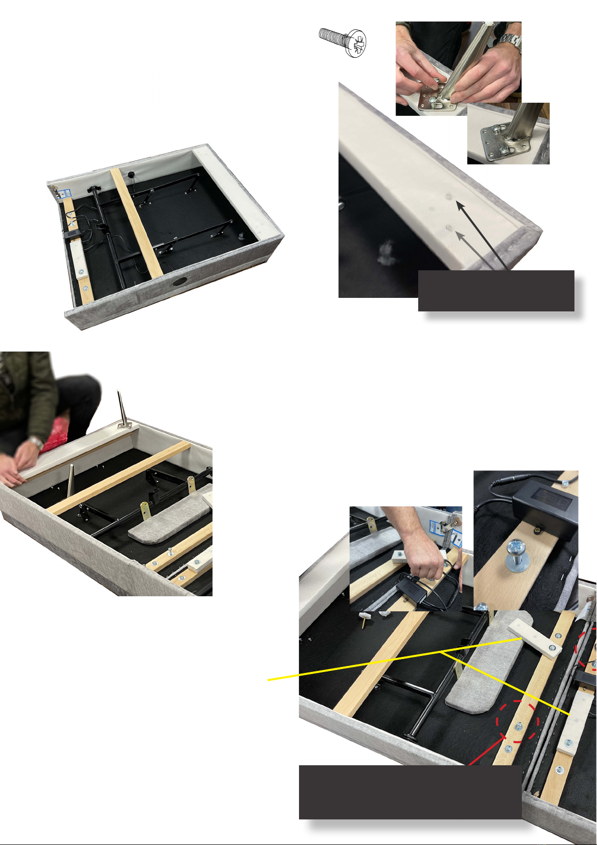
10. Attach the stiletto metal legs on
each corner of the bed by using the
30mm screws.
They should be at an angle and face
outwards as shown in this diagram.
11. Attach the retaining bar (put to one
side in stage 3).
To attach the retaining bar, indentify the
screws on the underneath of the bed (on
the foot end), and remove these screws.
12. Slide the retaining bar into the gap
between the bed frame and the top layer
of the bed at the foot end side.
• Put the screws at the foot end back
in to secure the top of the bed to the
frame.
13. Prepare for the electrical connection
instruction.
• Insure that all the wires have the
cable ties removed.
• Do not plug in your new bed until the
next stage is complete.
Position leg here
Position leg here
Slide into
this gap
Controller
Box
3. Connect the side rails to the head board
sliding the bolts into the bracket and tightening
with socket set.
• Repeat this process on the other side of
the headboard and the footboard.
PUSH DOWN
5. Screw the two wooden support blocks
into the Head and Footboard.
A secondary golden wood screw is
required on each to secure in place.
6. Screw the two further (60mm) wooden
blocks into the two baseboards. These are
pre-drilled for ease.
• Insert the ottoman baseboards into
the base unit as shown.
HEAD FOOT
HEADBOARD/
FOOTBOARD
4. Screw the 40mm wooden block into
the the pre-drilled support bar then insert
vertically across the bed between the two
side rails.
• The support rail is secured with a slide
on bracket as shown in the diagram.
Please Note: this step will require two
people and requires lifting.
40mm
60mm
SUPPORT
BLOCK
Remove this
protective sleeve
before fitting
PLEASE NOTE: It may be easier to rotate
the base onto it’s side for this step.

12. Attach the motor to the bed.
Identify the head and foot sides of
the motor by the images on each end
of the motor.
• Ensure your motor is the correct
way up, please use the highlighted
icons as your guide.
• Slide the caps off each side
of the motor.
• Place the motor on to the cross
bars until you hear it “click” into
position.
• Slide the caps back on to the
motor.
• Connect the Battery
(this is a safety back-up)
HEAD FOOT
Slide off covers Click onto bar Connect battery
Plug controler to
socket on motor
MOTOR-OKIN-88802 ON SURFACE
MOTOR-OKIN-92391 ON SPIRIT
Connect USB power
unit plug

CONNECT POWER
TO YOUR BED
This is a male ended
connector and
connects into the
motor directly.
Guide
for the Spirit Bed electrics
Connect
your remote to the bed
POWER
USB
MOTOR UNIT
CONTROLLER
BOX
PLUG INTO
SOCKET AND
POWER ON
PRESS BUTTON
TO ACTIVATE
PRESS TOP TWO
BUTTONS ON
REMOTE TO PAIR
CONNECT THE
CONTROLLER
CONNECT THE 9V
BATTERY
This is an important
back up power
source.
SPIRIT BED

Map
of the Spirit Bed Remote
Memory position one Memory position two
HEAD & FOOT UP button:
Press and hold the button, the Head
actuator will simultaneously go up.
Stop when released.
HEAD & FOOT DOWN button:
Press and hold the button, the Head
actuator will simultaneously go up.
Stop when released.
FOOT UP button:
Press and hold the button,
the Foot actuator will go up.
Stop when released.
FOOT DOWN button:
Press and hold the button,
the Foot actuator will go up.
Stop when released.
HEAD UP button:
Press and hold the button,
the Head actuator will go up.
Stop when released.
HEAD DOWN button:
Press and hold the button,
the Head actuator will go up.
Stop when released.
To Store
Memory Setting Under Bed Light
Torch
REMOTE
INSTRUCTIONS
M1 M2

CONNECT POWER
TO YOUR BED
This is a male ended
connector and
connects into the
motor directly.
Guide
for the Surface Bed electrics
Connect
your remote to the bed
POWER
USB
MOTOR UNIT
CONTROLLER
BOX
PLUG INTO
SOCKET AND
POWER ON
PRESS BUTTON
TO ACTIVATE
PRESS TOP TWO
BUTTONS ON
REMOTE TO PAIR
CONNECT THE
CONTROLLER
CONNECT THE 9V
BATTERY
This is an important
back up power
source.
SURFACE BED
M1 M2

Torch
Map
of the Surface Bed Remote
HEAD & FOOT UP button:
Press and hold the button, the Head
actuator will simultaneously go up.
Stop when released.
HEAD & FOOT DOWN button:
Press and hold the button, the Head
actuator will simultaneously go up.
Stop when released.
FOOT UP button:
Press and hold the button,
the Foot actuator will go up.
Stop when released.
HEAD UP button:
Press and hold the button,
the Head actuator will go up.
Stop when released.
FOOT DOWN button:
Press and hold the button,
the Foot actuator will go up.
Stop when released.
HEAD DOWN button:
Press and hold the button,
the Head actuator will go up.
Stop when released.
REMOTE
INSTRUCTIONS

If you have upgraded features
on your Spirit Bed
Your Remote and Electric Plan will be
slightly different.
Please follow the next few pages to guide you through the set up

Guide
for the Spirit Upgrade Features Bed electrics
Connect
your remote to the bed
USB
CONTROL
BOX
MOTOR UNIT
PRESS TOP TWO
BUTTONS ON
REMOTE TO PAIR
CONNECT THE
CONTROLLER
CONNECT THE 9V
BATTERY
This is an important
back up power
source.
UPGRADE SPIRIT BED
CONNECT POWER
TO YOUR BED
This is a male ended
connector and
connects into the
motor directly.
POWER
HE 150
CONTROL BOX
LIGHT
USB UNIT
USB UNIT
HEAD END
MASSAGE
UNIT
FOOT END
MASSAGE
UNIT
PRESS BUTTON
TO ACTIVATE
PLUG INTO
SOCKET AND
POWER ON

Map
of the Spirit Bed Features Upgrade Remote
Memory position one
Memory position two
Memory position three Massage Three
Massage Two
Massage One
HEAD & FOOT UP button:
Press and hold the button, the Head
actuator will simultaneously go up.
Stop when released.
HEAD & FOOT DOWN button:
Press and hold the button, the Head
actuator will simultaneously go up.
Stop when released.
FOOT UP button:
Press and hold the button,
the Foot actuator will go up.
Stop when released.
FOOT DOWN button:
Press and hold the button,
the Foot actuator will go up.
Stop when released.
HEAD UP button:
Press and hold the button,
the Head actuator will go up.
Stop when released.
HEAD DOWN button:
Press and hold the button,
the Head actuator will go up.
Stop when released.
To Store
Memory Setting On/Off Massage
Under Bed Light
Optional Extra
Torch
3
2
1
M1
M2
M3
Synchro mode on/off
Child safety lock on/off
REMOTE
INSTRUCTIONS

Your Furmanac Guarantee
We are delighted that you have bought one of Furmanac’s British, quality
hand made beds. Don’t forget, to obtain the full, 7 year guarantee you must
register your product online.
To do this, please visit www.furmanac.com/registermyguarantee and
complete the online form within 30 days of delivery to your address.
Your upholstered bed frame is provided with a standard 1 Year Guarantee,
protecting you against manufacturing defects. When you register for your
guarantee online this will be extended to our 7 Year Guarantee.
If you feel that your product has developed a fault within your guarantee
period then please follow the process below. However, prior to starting this
procedure Furmanac strongly recommends reviewing all the information on
the following pages to confirm that the issue is in fact a manufacturing fault.
Please note:
This guarantee is a back to
base guarantee and we are not
obliged to repair or replace
our product in the end user’s
premises.
This guarantee is valid from date of delivery to our customer’s address and we reserve right at our
discretion to repair or replace any parts that are faulty subject to the following conditions;
• The product has only being used for domestic use
• The original proof of purchase can be provided
• The product has remained with the original owner and has not been resold or gifted
• The product has been used in accordance with the care and safety guidelines outlined in this document
• The product has not been modified or attempted to be repaired by any person not authorised by Furmanac
• For the complete terms and conditions please visit www.furmanac.com

Making a claim;
Defects due to causes other than faulty materials or workmanship are non –
manufacturing faults and will therefore not be considered for repairs / replacement /
servicing;
Smells relating to your Hesita Motion mattress
You may smell some initial odours when the packaging of your new mattress has been
removed. In most cases this stem from the fire retardant used and for the vast majority
this smell goes unnoticed.
For those with the blessing / curse of a heightened sense of smell, you may feel that
your new mattress has a damp aroma. To dissipate this, we recommend airing your
mattress in a well ventilated room for a few hours upon delivery and then subsequently
stripping both the bed and mattress once a month to allow the mattress to air.
Body indentations
Initial body indentations may be visible when the mattress is first used, this is common
and is simply a result of the normal settlement of the mattress. However, the guarantee
does cover deterioration within the mattress that has caused permanent indentations,
providing there has been no misuse that may have aggravated the problem.
Perceived level of comfort
Whether purchased online or from a retail store, the perceived level of comfort
and firmness is subjective and therefore cannot be used as the foundation of a
manufacturing fault claim.
Abuse, Misuse and General Wear and Tear
Use of a non Hestia Motion base
The performance of your Hestia Motion mattress cannot be predicted on a non Hestia Motion base.
Bases that have not been manufactured by Furmanac may feature different mechanisms and/or adjust
to different angles consequently causing extra stress on your mattress. Consequently, any Hestia Motion
mattress not used on a Hestia Motion branded base will not be covered by the guarantee.
Use of non Hestia Motion mattress
Your Hestia Motion base has been designed to work with Furmanac adjustable mattresses. Non Hestia
motion mattresses may be too heavy / too light and consequently inhibit the performance of the
adjustable base and possibly even damage it. It is for these reasons that bases that have not been used
with the specified mattress will not be covered.
Other
• Use without bed linen on the mattress.
• Removal of a mattress cover that has not been explicitly labelled as having a “removable, washable cover”.
• Soiling / wetting / leaving the product in an unsanitary condition.
• Failure to follow the instructions regarding rotation / turning of the mattress outlined on the mattress label.
• Subjecting the product to excessive wear and tear e.g. jumping up and down on the bed.
• Overloading any drawers with weight more than 5kg.
• Where the mattress and/or base has been resold / gifted to a new owner.
• Exceeding the recommended weight limit of
• 25 stone on a 3’0 / 4’0 Mirage
• 28 stone on a 3’0 Independent / Salisbury
• 35 stone on a 4’0 / 4’6 Independent / Salisbury
• 50 stone on a 5’0 / 6’0 Mirage
• 56 stone on a 5’0 / 6’0 Independent / Salisbury
• Sleeping in the bed with the head end in a raised positioned.
• Applying force / pressure to the head end whilst operating or in an upright position.
Table of contents
Other Furmanac Indoor Furnishing manuals
Popular Indoor Furnishing manuals by other brands

Guardian
Guardian Guardian Automatic Overbed Table IC-6417 User instructions

PENTAGON
PENTAGON TambourGuard user manual

Hay
Hay NEW ORDER 1A instruction manual

Walker Edison
Walker Edison W60UBCT Assembly instructions

IKEA
IKEA sektion manual

Furniture of America
Furniture of America FOA7173Q Assembly instructions

Linon
Linon 58036SIL-01-KD-U Assembly instructions

YitaHome
YitaHome FWYIH0000572FW Assembly instructions

Argos
Argos 609/0131 Assembly instructions

VECELO
VECELO KHD-XF-TTR01-BLK Assembly instructions

Cooper Lighting
Cooper Lighting PM124cb Specification sheet

Furniture of America
Furniture of America CM3794PC-2PK Assembly instructions