manuals.online logo
Brands
  1. Home
  2. •
  3. Brands
  4. •
  5. Furuno
  6. •
  7. Marine Radar
  8. •
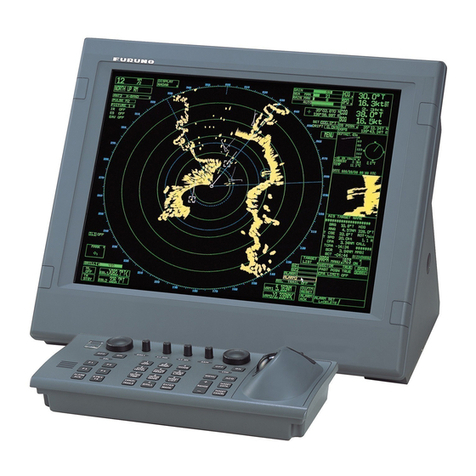
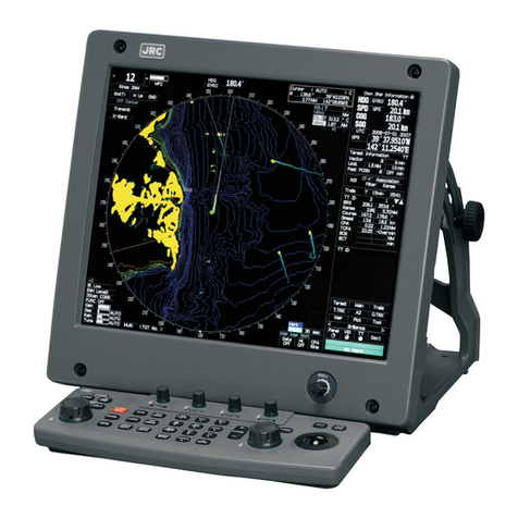
  9. Furuno FAR-2218 User manual

Furuno FAR-2218 User manual

Other manuals for FAR-2218

4

This manual suits for next models

20

Other Furuno Marine Radar manuals

Furuno FAR-28 Series User manual

Furuno

Furuno FAR-28 Series User manual

Furuno FR-7041R-MARK-2 User manual

Furuno

Furuno FR-7041R-MARK-2 User manual

Furuno FR-2855 User manual

Furuno

Furuno FR-2855 User manual

Furuno 1833 User manual

Furuno

Furuno 1833 User manual

Furuno FR-8045 User manual

Furuno

Furuno FR-8045 User manual

Furuno 1935DISP User manual

Furuno

Furuno 1935DISP User manual

Furuno 1715 User manual

Furuno

Furuno 1715 User manual

Furuno NAVnet 1722C User manual

Furuno

Furuno NAVnet 1722C User manual

Furuno FR-2155 User manual

Furuno

Furuno FR-2155 User manual

Furuno 1622 User manual

Furuno

Furuno 1622 User manual

Furuno FR-1505 User manual

Furuno

Furuno FR-1505 User manual

Furuno FAR-2318 User manual

Furuno

Furuno FAR-2318 User manual

Furuno FR-1918V-BB User manual

Furuno

Furuno FR-1918V-BB User manual

Furuno FCR-2107 series User manual

Furuno

Furuno FCR-2107 series User manual

Furuno FAR-1513-BB User manual

Furuno

Furuno FAR-1513-BB User manual

Furuno BBDS1 User manual

Furuno

Furuno BBDS1 User manual

Furuno 851 MARK-2 User manual

Furuno

Furuno 851 MARK-2 User manual

Furuno FCR-902 User manual

Furuno

Furuno FCR-902 User manual

Furuno FR-7010D User manual

Furuno

Furuno FR-7010D User manual

Furuno FR-2115/2125 User manual

Furuno

Furuno FR-2115/2125 User manual

Furuno FR-1710 User manual

Furuno

Furuno FR-1710 User manual

Furuno FR-810DS User manual

Furuno

Furuno FR-810DS User manual

Furuno FAR-3210 Manual

Furuno

Furuno FAR-3210 Manual

Furuno DRS2D User manual

Furuno

Furuno DRS2D User manual

Popular Marine Radar manuals by other brands

JRC JMR-9230-S installation manual

JRC

JRC JMR-9230-S installation manual

RADAC WaveGuide 5 Onboard 2 user manual

RADAC

RADAC WaveGuide 5 Onboard 2 user manual

JRC JMA-9922-6XA instruction manual

JRC

JRC JMA-9922-6XA instruction manual

Koden MDC-1810P Operation manual

Koden

Koden MDC-1810P Operation manual

JRC JMA-5208HS Simplified manual

JRC

JRC JMA-5208HS Simplified manual

Koden MDC-2240 Operation manual

Koden

Koden MDC-2240 Operation manual

JRC JMA-5212-4 installation manual

JRC

JRC JMA-5212-4 installation manual

Sailor SP4400 operating instructions

Sailor

Sailor SP4400 operating instructions

JRC JMA-5312-6/6HS installation manual

JRC

JRC JMA-5312-6/6HS installation manual

Grundig GSS STC 816 Assembly instruction

Grundig

Grundig GSS STC 816 Assembly instruction

Anritsu RA773UA instruction manual

Anritsu

Anritsu RA773UA instruction manual

Simrad CR44 manual

Simrad

Simrad CR44 manual

Brainlab KICK 2 System and Technical User Guide

Brainlab

Brainlab KICK 2 System and Technical User Guide

Icom MXR-5000R instruction manual

Icom

Icom MXR-5000R instruction manual

Garmin GMR 20 Specifications

Garmin

Garmin GMR 20 Specifications

Raymarine Pathfinder Radar Scanners Owner's handbook

Raymarine

Raymarine Pathfinder Radar Scanners Owner's handbook

ALDEN OneLight 65 SSC user guide

ALDEN

ALDEN OneLight 65 SSC user guide

Sony MPK-DVF7 O-ring Service manual

Sony

Sony MPK-DVF7 O-ring Service manual

manuals.online logo
manuals.online logoBrands
  • About & Mission
  • Contact us
  • Privacy Policy
  • Terms and Conditions

Copyright 2025 Manuals.Online. All Rights Reserved.

www.furuno.com
A
ll brand and product names are trademarks, registered trademarks or service marks of their respective holders.
Installation Manual
MARINE RADAR
Model
FAR-2218(-BB)/2228(-BB)/2318/2328/
FAR-2238S(-BB/-NXT/-NXT-BB)/
FAR-2338S(-NXT)/2328W/2338SW/
FAR-2258(-BB)/2358
SAFETY INSTRUCTIONS ........................i
SYSTEM CONFIGURATION ..................iii
EQUIPMENT LISTS...............................xii
1. INSTALLATION...............................1-1
1.1 Antenna Unit (X-band Radar) .............1-1
1.2 Antenna Unit (S-band Radar) ...........1-11
1.3 Monitor Unit.......................................1-17
1.4 Control Unit.......................................1-17
1.5 Power Supply Unit ............................1-24
1.6 Processor Unit ..................................1-25
1.7 Transceiver Unit................................1-27
1.8 Intelligent Hub (option)......................1-27
1.9 Switching Hub (option)......................1-28
1.10 Junction Box (option) ........................1-29
2. WIRING............................................2-1
2.1 Overview .............................................2-1
2.2 Antenna Unit for X-band,
TR-UP Radar ......................................2-5
2.3 Antenna Unit for X-band,
TR-DOWN Radar..............................2-19
2.4 Antenna Unit for S-band,
TR-UP Radar ....................................2-26
2.5 Antenna Unit for S-band,
TR-DOWN Radar..............................2-40
2.6 Power Supply Unit ............................2-46
2.7 Transceiver Unit................................2-53
2.8 Processor Unit ..................................2-59
2.9 Monitor Unit.......................................2-66
2.10 LAN Signal Converter .......................2-68
2.11 Junction Box (option) ........................2-71
2.12 Intelligent HUB (option).....................2-72
2.13 VDR Connection ...............................2-73
3. ADJUSTMENTS..............................3-1
3.1
How to Open the Radar Installation Menu
..3-3
3.2 How to Align the Heading ...................3-4
3.3 How to Adjust the Sweep Timing ........3-4
3.4 How to Suppress Main Bang ..............3-5
3.5 Other Settings .....................................3-6
3.6 How to Control Charts.......................3-26
4. INPUT/OUTPUT DATA ...................4-1
4.1 Processor Unit ....................................4-1
4.2 Sub Monitor.........................................4-3
APPENDIX 1 JIS CABLE GUIDE.....AP-1
APPENDIX 2
DIGITAL INTERFACE
..AP-2
PACKING LISTS ................................. A-1
OUTLINE DRAWINGS ........................ D-1
INTERCONNECTION DIAGRAMS ..... S-1
7KHSDSHUXVHGLQWKLVPDQXDO
LVHOHPHQWDOFKORULQHIUHH
࣭)85812$XWKRUL]HG'LVWULEXWRU'HDOHU
$VKLKDUDFKR
1LVKLQRPL\D-$3$1
$  129 

3ULQWHGLQ-DSDQ
$OOULJKWVUHVHUYHG
3XE1R 20($
*5(* )$5[[%%
 
Pub. No. IME-36520-E11
A : NOV. 2017
E11: FEB. 28, 2019
(AKMU) FAR-2xx8 series
i
SAFETY INSTRUCTIONS
Wear a safety belt and hard hat when working on the antenna unit.
Serious injury or death can result if someone falls from the radar antenna mast.
The installer must read the applicable safety instructions before attempting to operate or install the
equipment.
Indicates a potentially hazardous situation which, if not avoided,
will result in death or serious injury.
DANGER
Indicates a potentially hazardous situation which, if not avoided,
could result in death or serious injury.
WARNING
Indicates a potentially hazardous situation which, if not avoided,
can result in minor or moderate injury.
CAUTION
Warning, Caution Prohibitive Action Mandatory Action
DANGER
Construct a suitable service platform
from which to install the antenna unit.
Serious injury or death can result if
someone falls from the radar antenna
mast.
Do not open the equipment.
This equipment uses high voltage
electricity which can shock, burn or
cause serious injury. Only qualified
personnel can work inside the equipment.
WARNING
Turn off the power at the mains
switchboard before beginning the
installation.
Fire, electrical shock or serious injury can
result if the power is left on or is applied
while the equipment is being installed.
Be sure that the power supply is
compatible with the voltage rating of
the equipment.
Connection of an incorrect power supply
can cause fire or damage the
equipment.
Attach protective earth securely to the
ship's body.
The protective earth (grounding) is
required for the AC power supply to
prevent electrical shock.
WARNING
Use only the specified power cable.
Fire or damage to the equipment can
result if a different cable is used.
Do not install the units (other than the
antenna unit) in a dusty environment,
or one where the units may get wet
from rain or water splash.
Dust or water in the units can result in
fire, electrical shock, or damage to the
equipment.
SAFETY INSTRUCTIONS
ii
Observe the following compass safe distances to prevent deviation of a magnetic
compass:
Note: For more information,
please refer to IMO
SN/Circ.271 “Guidelines for
the installation of shipborne
radar equipment.”
2.15 m 1.40 m
2.45 m 1.60 m
3.05 m 1.90 m
1.90 m 1.20 m
CAUTION
Radio Frequency Radiation Hazard
*: XN12CF: 4 ft, XN20CF: 6.5 ft, XN24CF/XN24AF: 8 ft, SN24CF: 8 ft, XN30AF/SN30CF: 10 ft, SN36CF: 12 ft
**: Unavailable on IMO-type radars
FAR-2218(-BB)
FAR-2318 RTR-105 (12 kW)
RTR-111 (250 W)
RTR-106 (25 kW)
RTR-108 (25 kW)
RTR-107 (30 kW)
RTR-109 (30 kW)
XN12CF
XN20CF
XN24CF
FAR-2228(-BB)
FAR-2328
FAR-2338S
The radar antenna emits electromagnetic radio frequency (RF) energy which can be harmful,
particularly to your eyes. Never look directly into the antenna aperture from a close distance while the radar is in
operation or expose yourself to the transmitting antenna at a close distance. Distances at which RF radiation
level of 100, 50 and 10 W/m
2
are given in the table below.
If the antenna unit is installed at a close distance in front of the wheel house, your administration may require
halt of transmission within a certain sector of antenna revolution. See the installation manual for how to manage
blind sectors.
XN12CF
XN20CF
XN24CF
0.6 m
0.4 m
0.3 m
1.3 m
1.0 m
0.7 m
1.4 m
0.9 m
0.6 m
2.7 m
1.7 m
1.3 m
4.4 m
3.0 m
2.5 m
9.5 m
6.8 m
5.5 m
FAR-2328W
FAR-2238S(-BB)
FAR-2338S-NXT
FAR-2238S-NXT(-BB)
FAR-2338SW
XN20CF
XN24CF
SN24CF**
SN30CF**
SN36CF
SN24CF**
SN30CF**
SN36CF
SN36CF
0.5 m
0.3 m
N/A 0.26 m 2.3 m
1.2 m
0.9 m
5.5 m
4.0 m
WARNING
Model Transceiver Magnetron
FNE1201
MG5436
MG5223F
Antenna* 100 W/m
2
50 W/m
2
10 W/m
2
Magnetron
radar
Solid state
radar
1.7 m
1.4 m
N/A
N/A
N/A
N/A
N/A
N/A
N/A
2.4 m
2.1 m
0.5 m
3.8 m
3.4 m
4.6 m
N/A
N/A
1.0 m
FAR-2258(-BB)
FAR-2258/2358 RTR-122 XN24AF**
XN30AF**
2.3 m
2.3 m
4.5 m
4.3 m
13.9 m
13.9 m
9M31
0.30 m 0.30 m
4.05 m 2.65 m
Standard
compass
Unit
Steering
compass
Unit
Antenna Unit
(X-band, TR-UP,
12 kW)
Antenna Unit
(X-band, TR-UP,
50 kW)
Antenna Unit
(X-band, TR-UP,
25 kW)
Antenna Unit
(S-band, TR-UP,
solid state radar)
Antenna Unit
(S-band, TR-UP,
magnetron radar)
1.90 m 1.20 m
Antenna Unit
(X-band,
TR-DOWN)
1.55 m 0.95 m
Antenna Unit
(S-band,
TR-DOWN)
0.85 m 0.55 m
0.90 m 0.55 m
0.50 m 0.30 m
0.95 m 0.60 m
0.95 m 0.60 m
1.20 m 0.75 m
2.85 m 1.80 m
1.00 m 0.60 m
Junction Box
(RJB-001) 1.10 m 0.70 m
1.65 m 1.05 m
Unit
Control Unit
(RCU-014)
Control Unit
(RCU-015)
Control Unit
(RCU-016)
Control Unit
(RCU-031)
2.00 m 1.25 m
Transceiver Unit
(RTR-108)
4.50 m 2.90 m
Transceiver Unit
(RTR-109)
Processor Unit
(RPU-025)
1.30 m 0.80 m
Power Supply Unit
(PSU-019)
Monitor Unit
(MU-190)
Monitor Unit
(MU-231)
Monitor Unit
(MU-270W)
Intelligent HUB
(HUB-3000)
Switching HUB
(HUB-100)
Standard
compass
Steering
compass Standard
compass
Steering
compass
iii
SYSTEM CONFIGURATION
Standard connection
Basic configuration is shown with solid line. For footnotes, see "Notes" on page viii.
X-band (TR-UP), 12 kW/25 kW
NOTICE
IMO-type radar(s) must be interconnected to the following type approved sensors.
For other radar types, it is recommended to connect the following type approved sensors:
•
EPFS meeting the requirements of the IMO resolution MSC.112(73).
•
Gyrocompass (or equivalent devices) meeting the requirements of the IMO resolution A.424(XI).
•
SDME meeting the requirements of IMO resolution MSC.96(72).
The radar may be interconnected via HUB-3000 to other FURUNO processing units having approved
LAN ports.
100-230 VAC
1ø, 50-60 Hz
Transformer
USB Device*9
440 VAC
1ø, 50-60 Hz
USB Mouse
Switching Hub
HUB-100
Control Unit
RCU-014 or RCU-015
Control Unit RCU-016
Monitor Unit*3
MU-190 or
MU-231 or
MU-270W
Intelligent Hub
HUB-3000*5
Gyrocompass*1(AD-10 format)
Gyrocompass*1(IEC61162 format)
AIS Transponder
EPFS*2(GPS)
SDME (Speed log)
AMS (IEC61162 format)
Sub monitor 1 of ECDIS*8
Sub monitor 2 of ECDIS*8
AMS (Contact)*4
Sub monitor
Antenna Cable*10
100-115/220-230 VAC
1ø, 50-60 Hz (for de-icer)
Processor
Unit
RPU-025
Antenna Unit
for FAR-2218(-BB)/2318, 12 kW
(w/ Performance Monitor PM-32A
*7
)
XN12CF-RSB128-105
XN20CF-RSB128-105
XN24CF-RSB128-105
Antenna Unit
for FAR-2228(-BB)/2328, 25 kW
(w/ Performance Monitor PM-32A
*7
)
XN12CF-RSB128-106
XN20CF-RSB128-106
XN24CF-RSB128-106
100-230 VAC
100-230 VAC
Intelligent Hub
HUB-3000*6
100-230 VAC
OR
100-230 VAC
VDR
(IEC61162-450 format)
Sensors
(IEC61162-450 format)
VDR
(Analog RGB)
:
Standard supply
:
Optional or local supply
ECDIS
SYSTEM CONFIGURATION
iv
X-band (TR-UP), 50 kW
USB Device*9
USB Mouse
100-230 VAC
1ø, 50-60 Hz
100-230 VAC
1ø, 50-60 Hz
100-230 VAC
1ø, 50-60 Hz
100-230 VAC
1ø, 50-60 Hz
Transformer
440 VAC
1ø, 50-60 Hz
VDR
(Analog RGB)
Antenna Cable Motor Cable
Antenna Unit
for FAR-2258(-BB)/2358, 50kW
(w/ Performance Monitor PM-32A
*
7
)
XN24AF-RSB139-122
*
11
XN30AF-RSB139-122
*
11
:
Standard supply
:
Optional or local supply
100-115/220-230 VAC
1ø, 50-60 Hz
External radar
Sub monitor 2
Power Supply
Unit
PSU-019
Sensors
(IEC61162-450 format)
Antenna Cable (LAN+serial)
Sub monitor 3
Sub monitor 1
100-230 VAC
1ø, 50-60 Hz
VDR
(IEC61162-450 format)
Monitor Unit*3
MU-190/
MU-231/
MU-270W
Control Unit
RCU-014/
RCU-015/
RCU-031
Intelligent Hub
HUB-3000*5
Switching
Hub
HUB-100*6
Control Unit
RCU-014/
RCU-015/
RCU-031
Control Unit
RCU-016
Processor
Unit
RPU-025
Intelligent
Hub-
HUB-3000
OR
Gyrocompass*1(AD-10 format)
Gyrocompass
*1
(IEC61162 format)
AIS Transponder
EPFS*2(GPS)
AMS (IEC61162 format)
AMS (Contact)*4
Sub Monitor 1 of ECDIS*8
Sub Monitor 2 of ECDIS*8
ECDIS
SDME (Speed log)
SYSTEM CONFIGURATION
v
S-band (TR-UP)
Gyrocompass*1(AD-10 format)
Gyrocompass*1(IEC61162 format)
AIS Transponder
EPFS*2(GPS)
SDME (Speed log)
AMS (IEC61162 format)
ECDIS
AMS (Contact)*4
Sub monitor Antenna Cable
100-115/220-230 VAC
1ø, 50-60 Hz
(for de-icer)
Processor
Unit
RPU-025
Antenna Unit
for FAR-2238S(-BB)/2338S, 30 kW
(w/ Performance Monitor PM-52A*7
SN24CF-RSB129-107*11
SN30CF-RSB129-107*11
SN36CF-RSB129-107
Antenna Unit
for FAR-2238S-NXT(-BB)/2338S-NXT, 250 W
(w/ Performance Monitor PM-52B*7)
SN24CF-RSB133-111*11
SN30CF-RSB133-111*11
SN36CF-RSB133-111
Sub monitor 1 of ECDIS*8
Sub monitor 2 of ECDIS*8
Control Unit
RCU-014 or RCU-015
Control Unit RCU-016
:
Standard supply
:
Optional or local supply
USB Device*9
USB Mouse
100-230 VAC
1ø, 50-60 Hz
Transformer
440 VAC
1ø, 50-60 Hz
Switching Hub
HUB-100
Monitor Unit*3
MU-190 or
MU-231 or
MU-270W
Intelligent Hub
HUB-3000*5
100-230 VAC
100-230 VAC
Intelligent Hub
HUB-3000*6
100-230 VAC
OR
100-230 VAC
VDR
(IEC61162-450 format)
Sensors
(IEC61162-450 format)
VDR
(Analog RGB)
SYSTEM CONFIGURATION
vi
X-band (TR-DOWN)
Gyrocompass*1(AD-10 format)
Gyrocompass*1(IEC61162 format)
AIS Transponder
EPFS*2(GPS)
SDME (Speed log)
AMS (IEC61162 format)
ECDIS
AMS (Contact)*4
Sub monitor
Antenna Cable
100-115/220-230 VAC
1ø, 50-60 Hz
(for de-icer)
Processor
Unit
RPU-025
Transceiver Unit
RTR-108
Antenna Unit
for FAR-2328W, 25 kW
(w/ Performance Monitor PM-32A)
XN20CF-RSB130
XN24CF-RSB130
Wave guideSignal cable
Sub monitor 1 of ECDIS*8
Sub monitor 2 of ECDIS*8
Control Unit
RCU-014 or RCU-015
Control Unit RCU-016
:
Standard supply
:
Optional or local supply
USB Device*9
USB Mouse
100-230 VAC
1ø, 50-60 Hz
Transformer
440 VAC
1ø, 50-60 Hz
Switching Hub
HUB-100
Monitor Unit*3
MU-190 or
MU-231 or
MU-270W
Intelligent Hub
HUB-3000*5
100-230 VAC
100-230 VAC
Intelligent Hub
HUB-3000*6
100-230 VAC
OR
100-230 VAC
VDR
(IEC61162-450 format)
Sensors
(IEC61162-450 format)
VDR
(Analog RGB)
SYSTEM CONFIGURATION
vii
S-band (TR-DOWN)
Gyrocompass*
1
(AD-10 format)
Gyrocompass*
1
(IEC61162 format)
AIS Transponder
EPFS*
2
(GPS)
SDME (Speed log)
AMS (IEC61162 format)
ECDIS
AMS (Contact)*
4
Sub monitor
Antenna Cable
100-115/220-230 VAC
1ø, 50-60 Hz
(for de-icer)
Transceiver Unit
RTR-109
Antenna Unit
for FAR-2338SW, 30 kW
(w/ Performance Monitor PM-52A)
SN36CF-RSB131
Coaxial cableSignal cable
Processor
Unit
RPU-025
Sub monitor 1 of ECDIS*
8
Sub monitor 2 of ECDIS*
8
Control Unit
RCU-014 or RCU-015
Control Unit RCU-016
:
Standard supply
:
Optional or local supply
USB Device*
9
USB Mouse
100-230 VAC
1ø, 50-60 Hz
Transformer
440 VAC
1ø, 50-60 Hz
Switching Hub
HUB-100
Monitor Unit*
3
MU-190 or
MU-231 or
MU-270W
Intelligent Hub
HUB-3000*
5
100-230 VAC
100-230 VAC
Intelligent Hub
HUB-3000*
6
100-230 VAC
OR
100-230 VAC
VDR
(IEC61162-450 format)
Sensors
(IEC61162-450 format)
VDR
(Analog RGB)
SYSTEM CONFIGURATION
viii
Category of units
Antenna unit: Exposed to weather
Other units: Protected from the weather
Notes
1) The gyrocompass must be type approved for compliance with IMO resolution A.424(XI) (and/
or resolution A.821(19) for installation on HSC). The gyrocompass must also have an update
rate that is adequate for the ship’s rate of turn. The update rate must be better than 40 Hz
(HSC) or 20 Hz (conventional vessel).
2) The EPFS must be type approved for compliance with IMO resolution MSC.112(73).
3) These monitors have been approved by the IMO, MU-190 for CAT 2 and CAT 2H, MU-231/
MU-270W for CAT 1 and CAT 1H. If a different monitor is to be used on IMO vessels, its ef-
fective diameter must meet the Category requirements:
• CAT 1 and CAT 1H: effective diameter 320 mm or higher
• CAT 2 and CAT 2H: effective diameter 250 mm or higher
For installation, operation and viewing distance of other monitor, see its manuals.
For BB type, a monitor unit is prepared by user.
4) Characteristics of contact output for Alarm:
• (Load current) 250 mA
• (Polarity) Normally Open: 2 ports, Normally Close: 2 ports
• Serial I/O for alarm is also possible, which complies with IEC 61162-1.
5) For configurations with 3 or more radars/ECDIS (FMD-3100/FMD-3200/FMD-3300) connect-
ed, connect via the HUB-3000. For 2 radars, HUB-100 can be used. Connection to a FMD (EC-
DIS) is not available for C-type radars.
6) For configurations with a VDR connected, connect via the HUB-3000. Connection to a VDR is
not available for C-type radars.
7) Some antenna configurations do not have an in-built Performance Monitor. This type of anten-
na is not usable for IMO-type radars.
8) For connecting non-FURUNO ECDIS only. For connection of radars or plotters, the connection
must be done at the radar antenna (or the transceiver unit) via the sub monitor connector.
9) Available on C-type and A/B/W-type radars with Radar Plotter functionality
10)Junction boxes are required for antenna cable length greater than 100 m (only for TR-UP radar
of X-band). Max. cable length is 400 m.
11)Unavailable on IMO-type radars