System Fail
Power Fail
ACK IN
VDR
DVI-RGB Cable
100-230 VAC 1ø, 50-60 Hz
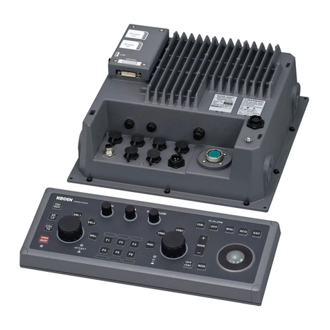
Control Unit
RCU-025
or
Trackball Control Unit
RCU-026
USB Keyboard
USB Mouse
INTERCONNECTION DIAGRAMINTERCONNECTION DIAGRAMSPECIFICATIONSSPECIFICATIONS
100 VAC
1ø, 50-60 Hz
200/380 VAC, 3ø, 50 Hz
220/440 VAC, 3ø, 60 Hz
200/380 VAC, 3ø, 50 Hz
220/440 VAC, 3ø, 60 Hz
* Up to 8 EC-3000 Processor Units can be
interfaced through single HUB-3000.
Option or connectable equipment
Model
FCR-2119
FCR-2129
FCR-2819
FCR-2829
FCR-2829W
FCR-2139S
FCR-2839S
FCR-2839SW
Output Power (Transceiver)
X band 12 kW (RTR-078A)
X band 25 kW (RTR-079A)
X band 12 kW (RTR-078A)
X band 25 kW (RTR-079A)
X band 25 kW (RTR-081A)
S band 30 kW (RTR-080)
S band 30 kW (RTR-080)
S band 30 kW (RTR-082)
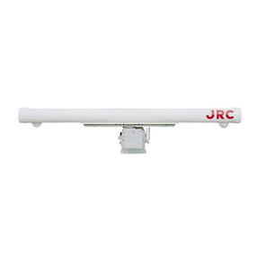
Antenna Length (Antenna Unit)
6.5 ft (XN-20AF)
8 ft (XN-24AF)
12 ft (SN-36AF)
Rotation (Gear Box)
24 rpm (RSB-103)
21 / 26 rpm (RSB-104/105)
24 rpm (RSB-096)
42 rpm (RSB-097)
21 / 26 rpm (RSB-098/099)
45 rpm (RSB-100/101/102)
Monitor Unit
19.0" SXGA (MU-190)
23.1" UXGA (MU-231)
23.1" UXGA (MU-231)
19.0" SXGA (MU-190)
23.1" UXGA (MU-231)
23.1" UXGA (MU-231)
Antenna XN-20AF (6.5 ft)
XN-24AF (8 ft)
Transceiver
RTR-078A (12 kw)
RTR-079A (25 kw)
Performance Monitor
PM-31
Antenna XN-20AF (6.5 ft)
XN-24AF (8 ft)
Antenna SN-36AF (12 ft) Antenna SN-36AF (12 ft)
Gear Box RSB-096 (24 rpm)
RSB-097 (42 rpm)
Gear Box RSB-103 (24 rpm) Gear Box RSB-098/99 (21/26 rpm)
RSB-100/101/102 (45 rpm)
Gear Box RSB-104/105 (21/26 rpm)
FCR-2119/2129/2819/2829 FCR-2829W FCR-2139S/2839S FCR-2839SW
Note:
1. Length of LAN cable is 50 m (max.)
2. Cable between Sensor Adapter components
should be no longer than 6 m.
Performance Monitor
PM-31
Performance Monitor
PM-51
Performance Monitor
PM-51
RTR-081A
Transceiver Unit
Transceiver
RTR-080(30 kW)
RTR-082
Transceiver Unit
PSU-007
Power Supply Unit
100-115/220-230 VAC
1ø, 50-60 Hz
100-115/220-230 VAC
1ø, 50-60 Hz
100-230 VAC
1ø, 50-60 Hz
100-230 VAC
24 VDC
Gyro Converter
GC-10
RPU-013
Radar Processor
Unit
Processor Unit EC-3000 for ECDIS and Chart Radar*
EC-3000
Processor Unit
DVI cable
RS-485
MU-190: 5/10 m (max.)
MU-231: 5 m (max.)
MU-190: 10 m (max.)
MU-231: 5 m (max.)
for Brill control
MU-190
19"
GYRO COMPASS
SUB DISPLAY
A-D CONVERTER
Intelligent Hub
HUB-3000
8 ports
Switching Hub
HUB-100
Sensor Adapter
Serial MC-3000S (8 ports)
Analog MC-3010A (3 ports)
Digital IN/OUT
MC-3020D/3030D
(8 ports each)
Navigation Sensors
Gyrocompass
AIS
GPS
NAVTEX
Wind Indicator
Echo Sounder
Speed Log
Water Temp. Sensor
etc.
MU-231
23.1"
Monitor Unit
GENERAL
Minimum range
Range discrimination
Bearing accuracy
Presentation modes
22 m
26 m
±1°
Head-up, Head-up TB, Course-up, North-up, True Motion
(sea or ground stabilization in True Motion)
ANTENNA UNIT
Radiator Type
Beamwidth and Sidelobe
Slotted waveguide array
RADAR PROCESSOR UNIT
PROCESSOR UNIT
Chart Materials
Data Presentation
Own Ship
Target Data
(TT: ARPA, AIS)
Position Calculation
Navigation Planning
Navigation Recording
Route Monitoring
User Chart
Notes Data
MOB (Man Overboard)
IMO/IHO S57 edition-3 ENC vectorized material
(IHO S-63 ENC data protection scheme),
C-MAP and CM-93/3 vectorized materials
Own ship's mark and numeral position in lat/lon,
speed and course
Range, bearing, speed, course, CPA/TCPA, BCR/BCT
Target information from AIS (waypoint, ship's hull and status)
Navigation by result from external position sensor
Dead reckoning with gyro and log data from gyro, log,
and position sensors to be fed to mathmatical filter to
generate highly accurate position and speed
Planning by rhumb line, great circle
Latest 12 hours of navigation data to be recorded
Off-track display, waypoint arrival alarm, shallow depth alarm
User chart creation and display
Create and display notes data
Position, and other data at time of man overboard are
recorded MOB mark is displayed on the screen
INTERFACE
DVI
LAN
USB
COM
Serial I/O
Digital IN
Contact Closure
3 ports, DVI-I Ver 1.1
(Video signal from DVI No. 1 and DVI No. 2 is identical)
3 ports, Ethernet 1000 Base-T
(1port for Radar sensor only)
4 ports, USB 2.0 type-A
2 ports, RS-485 for brilliance control
8 ports, IEC61162-1/2 (2 ports), IEC61162-1 (6 ports)
Sentences: AAM, ABK, ABM, ACK, ALR, BBM, BWC, BWR,
DBT, DPT, DTM, ETL, GBS, GGA, GLL, GNS, HDT, MTW,
MWD, MWV, OSD, RMB, RMC, ROT, RSD, RTE, THS,
TTM, VBW, VDM, VDO, VHW, VTG, WPL, ZDA
1 port, ACK signal input
6 ports: 1 port for system fail, 1 port for power fail,
2 ports for normal close, and 2 ports for nomal open
Radiator Type
Length
Beamwidth (H)
Beamwidth (W)
Frequency
Sidelobe (within ±10°)
Sidelobe (outside ±10°)
XN-20AF
6.5 ft
1.23°
20°
-28 dB
-32 dB
XN-24AF
8 ft
0.95°
20°
-28 dB
-32 dB
X band: 9410±30 MHz
SN-36AF
12 ft
1.8°
25°
S band: 3050±30 MHz
-24 dB
-30 dB
MONITOR UNIT
Monitor Unit
Display Type
Resolution
MU-190
19" color LCD
SXGA (1280×1024 pixels)
MU-231
23.1" color LCD
UXGA (1600×1200 pixels)
Pulselength, Pulse Repetition Rate (PRR) and Range scale
*500 Hz on 96/120 NM range
**2200Hz on TT range = 32 NM
Pulselength (μs)
PRR (Hz approx.)
Range scale (NM)
0.07
3000**
0.125/0.25/
0.5/0.75/1/
1.5/2
0.15
3000**
0.5/0.75/
1/1.5/2/3/4
0.3
1500
0.75/1/1.5/
2/3/4/6/8
0.5
1000
3/4/6/8/
12/16/24
0.7
1000
3/4/6/8/
12/16/24
1. 2
600*
6/8/12/16/
24/32/48/
96/120
Range scales (NM)
Ring intervals (NM)
Number of Rings
0.125
0.025
5
6
1
6
4
1
4
3
0.5
6
2
0.5
4
1. 5
0.25
6
1
0.25
4
0.75
0.25
3
0.5
0.1
5
0.25
0.05
5
Range Scales and Ring Intervals
1, 2, 4, 8, 16, 32, 72, 120 NM cannot be selected on IMO radar.
Range scales (NM)
Ring intervals (NM)
Number of Rings
8
2
4
120
20
6
96
16
6
72
12
6
48
8
6
32
8
4
24
4
6
16
4
4
12
2
6Model
FCR-2139S(-BB)
FCR-2839S
3.0A
3.0A
1.5A
1.5A
3.5A
-
3.5A
-
3.5A
-
Antenna voltage input (100 kn)
200 VAC,
ø3, 50 Hz,
220 VAC,
ø3, 60 Hz
380 VAC,
ø3, 50 Hz,
440 VAC,
ø3, 60 Hz
220 VAC,
ø3, 50 Hz,
(HSC)
220 VAC,
ø3, 60 Hz,
(HSC)
440 VAC,
ø3, 60 Hz,
(HSC)
1 port, Ethernet 100 Base-TX
8 ports, IEC 61162-1/2 (4 ports), IEC 61162-1 (4 ports)
1 port for system fail, normal close or normal open
3 ports/per unit, -10 to +10V/0 to 10 V, 4 to 20 mA selectable
8 ports/per unit, normal close or open, selectable
8 ports/per unit, normal close or open, selectable
SENSOR ADAPTER
Control and Serial Input
LAN
Serial
Contact Closure
Analog Input
Digital IN
Digital Output
-15°C to +55°C
-25°C to +55°C (storage +70°C)
93 % or less at 40°C
IP22
IPX0
IP20 (IP22: option)
IPX0
IP22
IPX6
IEC 60945 Ed.4
ENVIRONMENTAL CONDITIONS
Ambient Temperature
Monitor/processor/transceiver/
control/power supply unit
Antenna unit
Relative Humidity
Degree of protection
Monitor unit
Processor unit
RPU-013
EC-3000
Transceiver/power supply unit
Control unit
Antenna unit
Vibration
EQUIPMENT LIST
Standard
Monitor Unit
Radar Processor Unit
Processor Unit
Control Unit
Control Unit
Trackball Control Unit
Antenna Radiator
Transceiver
Gear Box
Power Supply Unit for S-band (FCR-2139S/2839S)
Cable between Radar Processor and Antenna Unit
LAN Cable between Radar Processor Unit and
Processor Unit
Power Switch Cable between Radar Processor Unit
and Processor Unit
Standard Spare Parts and Installation Materials
MU-190/MU-231
RPU-013
EC-3000
RCU-025
RCU-026
XN-20AF/XN-24AF/SN-36AF
RTR-078A/079A/080/081A/082
RSB-096/097/098/099/100/101/
102/103/104/105
PSU-007
Option
Performance Monitor for X-band/S-band
Sensor Adapter
Gyro interface
Slave Radar Cable
Switching Hub for sensor network
Intelligent Hub for interswitch network
Installation Materials
PM-31/51
MC-3000S/3010A/3020D/3030D
GC-10
RW-4864
HUB-100
HUB-3000
1unit
1unit
1unit
1unit
1unit*
1unit*
1unit
1unit
1unit
1unit
1 pc
1 pc
1 pc
1 set
S-band: 200/220/380/440 VAC, 4 phase, 50/60 HzAntenna unit
24 VDC, 1.4 ASensor Adapter
POWER SUPPLY
Monitor unit
MU-231
MU-190
Processor unit
RPU-013
EC-3000
100-230 VAC; 1.0-0.6 A, 1 phase, 50/60 Hz
100-230 VAC; 0.7-0.4 A, 1 phase, 50/60 Hz
FCR-2119(-BB)/2819:
100-115 VAC: 2.6 A (3.0 A), 220-230 VAC: 1.6 A (1.7 A)
FCR-2129(-BB)/2829:
100-115 VAC: 3.0 A (3.4 A), 220-230 VAC: 1.8 A (1.9 A)
( ): Value for 42 rpm antenna unit
FCR-2829W:
100-115 VAC: 3.2 A, 220-230 VAC: 1.6 A
FCR-2139S(-BB)/2839S/2839SW:
100-115 VAC: 3.0 A, 220-230 VAC: 1.5 A
100-115/220-230 VAC, 1 phase, 50/60 Hz
* Specify when ordering
Target Tracking (TT)
Acquisition
Auto tracking
Tracking
100 targets in 0.1-24(32) NM (Auto or Manual)
All acquired targets
5/10 points on all targets


