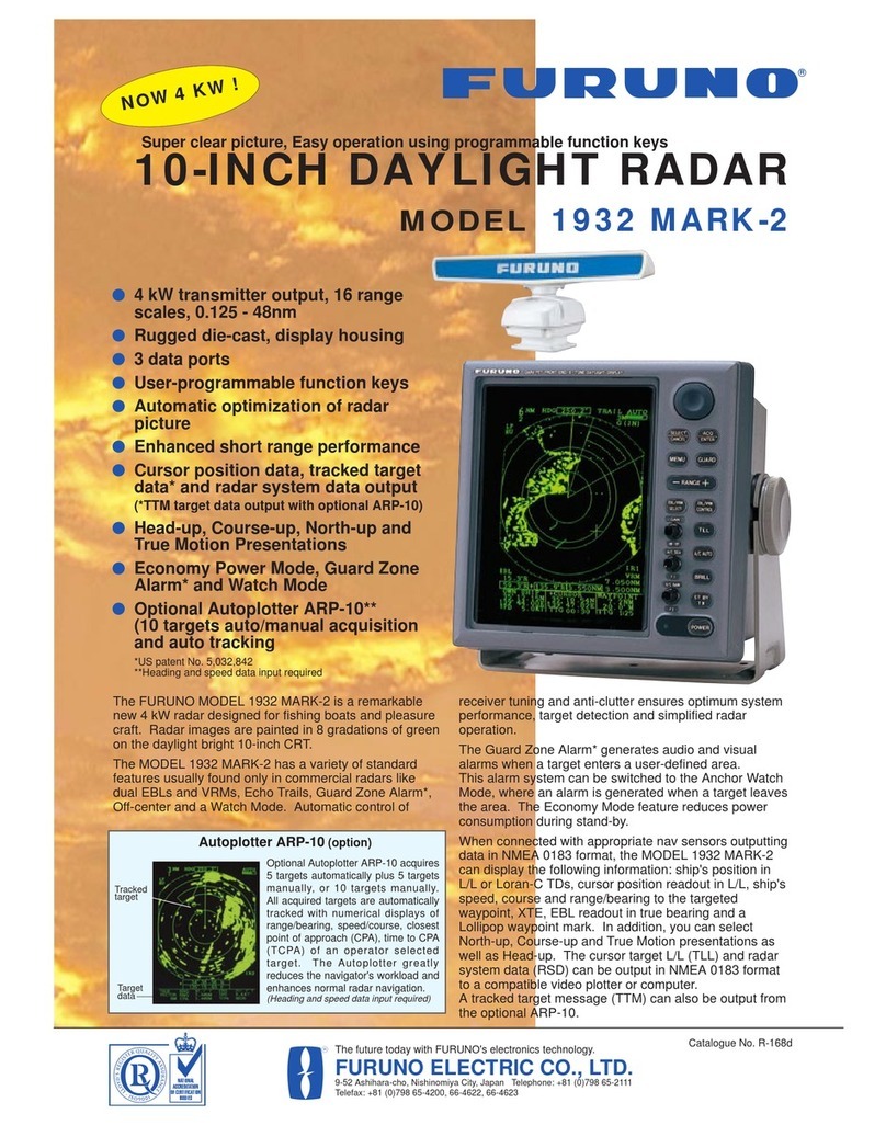
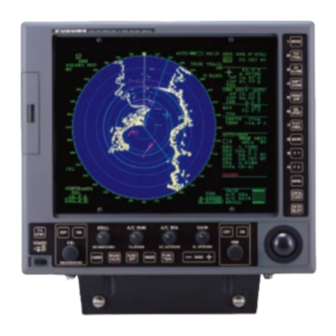
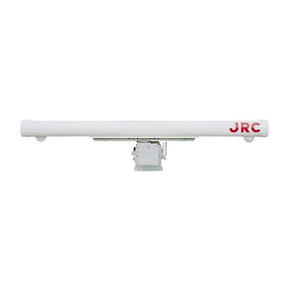
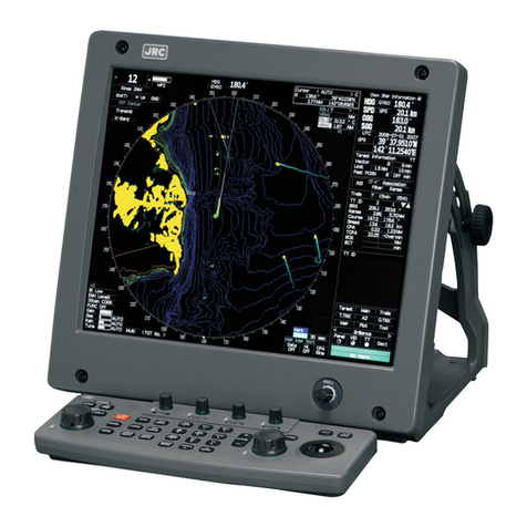
Furuno FCR-2829W User manual

www.furuno.com
A
ll brand and product names are trademarks, registered trademarks or service marks of their respective holders.
Installation Manual
CHART RADAR
Model FCR-2829W/2839SW
(Product Name: MARINE RADAR)
SAFETY INSTRUCTIONS ........................i
SYSTEM CONFIGURATIONS................iii
EQUIPMENT LISTS................................vi
1. MOUNTING......................................1-1
1.1 Antenna Unit .......................................1-1
1.2 Monitor Unit.......................................1-12
1.3 Radar Control Unit/
Trackball Control Unit .......................1-12
1.4 Radar Processor Unit........................1-15
1.5 Processor Unit ..................................1-16
1.6 Sensor Adapter MC-3000S/3010A/
3020D/3030D (option) ......................1-18
1.7 Intelligent Hub HUB-3000 (option)....1-19
1.8 Switching HUB HUB-100 (option).....1-20
2. WIRING............................................2-1
2.1 Interconnection ...................................2-1
2.2 Antenna Unit .......................................2-3
2.3 Transceiver Unit..................................2-9
2.4 Radar Processor Unit........................2-14
2.5 Processor Unit ..................................2-18
2.6 Monitor Unit.......................................2-29
2.7 Sensor Adapters (option)..................2-30
2.8 Intelligent HUB HUB-3000 (option)...2-49
2.9 How to Extend the Control Unit Cable
(option)..............................................2-50
3. SETTING AND ADJUSTMENTS.....3-1
3.1 How to Access the Radar Installation
Menu...................................................3-1
3.2 How to Align the Heading ...................3-1
3.3 How to Adjust the Sweep Timing........3-2
3.4 How to Suppress Main Bang ..............3-2
3.5 Dual Radar Display.............................3-3
3.6 Other Settings.....................................3-6
3.7 Web Setting Menu ............................3-12
4. INSTALLING OPTIONAL
EQUIPMENT ....................................4-1
4.1 Gyro Converter GC-10........................4-1
4.2 Junction Box .......................................4-9
5. INPUT/OUTPUT DATA ...................5-1
5.1 Radar Processor Unit..........................5-1
5.2 Processor Unit ....................................5-1
5.3 IEC 61162 Sentences .........................5-2
APPENDIX 1 JIS CABLE GUIDE.....AP-1
APPENDIX 2 ROD TERMINALS ......AP-2
APPENDIX 3
DIGITAL INTERFACE
....AP-8
PACKING LISTS ................................. A-1
OUTLINE DRAWINGS ........................ D-1
INTERCONNECTION DIAGRAMS ..... S-1
The paper used in this manual
is elemental chlorine free.
・FURUNO Authorized Distributor/Dealer
9 52 Ashihara cho,
Nishinomiya, 662 8580, JAPAN
A
:
JUN
2012
.
Printed in Japan
All rights reserved.
G1
:
JAN
.
05, 2017
Pub. No.
IME-36100-G1
(
REFU
)
FCR-2829 /2839S
0 0 0 1 7 6 1 3 9 1 6

i
SAFETY INSTRUCTIONS
Indicates a potentially hazardous situation which, if not avoided,
could result in death or serious injury.
ow
22 2
2
The operator and installer must read the applicable safety instructions before attempting to
install or operate the equipment.
WARNING
Indicates a potentially hazardous situation which, if not avoided,
canresult in minor or moderate injury.
Warning, Caution Prohibitive Action
CAUTION
Mandatory Action
DANGERDANGER
Wear a safety belt and hard hat when working on the antenna unit.
Serious injury or death can result if someone falls from the radar antenna mast.
WARNINGWARNING
Radio Frequency Radiation Hazard
The radar antenna emits electromagnetic radio frequency (RF) energy which can be
harmful, particularly to your eyes. Never look directly into the antenna aperture from a
close distance while the radar is in operation or expose yourself to the transmitting
antenna at a close distance.
Distances at which RF radiation levels of 100, 50 and 10 W/m are given in the table
below.
Note: If the antenna unit is installed at a close distance in front of the wheel house,
your administration may require halt of transmission within a certain sector of antenna
revolution. This is possible. Ask your FURUNO representative or dealer to provide
this feature.
Model Transceiver Magnetron Antenna
*
100W/m 50W/m 10W/m
FCR-2829W
FCR-2839SW
RTR-081A
(X-25 kw)
RTR-082
(S-30 kw)
MG5436
MG5223F
XN-20AF
XN-24AF
SN-36AF
0.4 m
0.2 m
--
1.0 m
0.5 m
0.2 m
5.6 m
3.4 m
1.9 m
*XN20AF: 6.5 ft XN24AF: 8 ft SN36AF: 12 ft

SAFETY INSTRUCTIONS
ii
WARNING
Do not open the equipment
unless totally familiar with
electrical circuits and
service manual.
Only qualified personnel
should work inside the
equipment.
ELECTRICAL
SHOCK
HAZARD
Construct a suitable service platform
from which to install the antenna unit.
Serious injury or death can result if some-
one falls from the radar antenna mast.
Turn off the power at the mains switch-
board before beginning the installation.
Fire, electrical shock or serious injury can
result if the power is left on or is applied
while the equipment is being installed.
Be sure that the power supply is
compatible with the voltage rating of
the equipment.
Connection of an incorrect power supply
can cause fire or damage the equipment.
Use only the specified power cable.
Fire or damage to the equipment can
result if a different cable is used.
Do not install the monitor unit,
processor unit or control unit where
they may get wet from rain or
water splash, or in a dusty environment.
Water in the units can result in fire,
electrical shock, or damage the equipment.
Attach protective earth
securely to the ship's body.
The protective earth
(grounding) is required for the
AC power supply to prevent
electrical shock.
CAUTION
Observe the following compass safe
distances to prevent deviation of a
magnetic compass:
Antenna Unit
(FCR-2829W)
Standard
compass
Steering
compass
1.15 m 0.70 m
Antenna Unit
(FCR-2839SW) 1.35 m 0.85 m
Transceiver Unit
(FCR-2829W) 2.00 m 1.30 m
Transceiver Unit
(FCR-2839SW) 4.25 m 2.75 m
Processor
Unit(EC-3000) 2.40 m 1.55 m
Monitor Unit
(MU-231) 2.55 m 1.55 m
ECDIS Control
Unit (RCU-024) 0.30 m 0.30 m
Radar Control
Unit (RCU-025) 0.30 m 0.30 m
Trackball Control
Unit (RCU-026) 0.30 m 0.30 m
Intelligent HUB
(HUB-3000) 1.20 m 0.75 m
Sensor Adapter
(MC-3000S) 2.05 m 1.35 m
Sensor Adapter
(MC-3010A) 0.75 m 0.50 m
Sensor Adapter
(MC-3020D) 1.05 m 0.70 m
Radar Processor
Unit (RPU-013) 1.35 m 0.85 m
Sensor Adapter
(MC-3030D) 0.90 m 0.60 m
Junction Box
(RJB-001) 1.10 m 0.70 m
Switching HUB
(HUB-100) 1.00 m 0.60 m
Note
For more information, please refer to IMO
SN/Circ.271 “Guidelines for the installa-
tion of shipborne radar equipment.”

iii
SYSTEM CONFIGURATIONS
FCR-2829W
NOTICE
The radar(s) must be interconnected to the following type approved sensors:
Gyrocompass meeting the requirements of the IMO resolution A.424(XI).
EPFS meeting the requirements of the IMO resolution MSC.112(73).
SDME meeting the requirements of IMO resolution MSC.96(72).
The radar may be interconnected via HUB-3000 to other FURUNO processing
units having approved LAN ports.
RPU-013
RADAR
PROCESSOR
UNIT
Sub Display 1
Sub Display 2
Gyro Converter
GC-10
Gyrocompass
A-D Converter
Heading Sensor
LAN
110-115/220-230 VAC
1
ø
, 50/60 Hz
Transformer
RU-1803
440VAC
1
ø
, 50/60 Hz Brake Unit
BR-001/002
EC-3000
PROCESSOR
UNIT
Serial 1, 2
IEC-61162-2
(Gyrocompass1), AIS)
Serial 3 - 8
IEC-61162-1
(EPFS2)(navigator),
SDME3)(Speed Log),
Echo sounder,
Wind, Alarm****,
Navtex, etc.)
Digital Out 1 - 6****
1: System Fail
2: Power Fail
3: Normal Close 1
4: Normal Close 2
5: Normal Open 1
6: Normal Open 2
Dashed lines indicate
optional or local supply
equipment.
Sensor Adapter**
or Switching HUB HB-100
Radar Control
Unit RCU-025
OR
Trackball Control Unit
RCU-026
ECDIS Control Unit
RCU-024
OR
Radar Control
Unit RCU-025
OR
Trackball Control Unit
RCU-026
Monitor Unit
MU-231*
Digital In (ACK IN)
VDR
Intelligent Hub
HUB-3000 100-115/220-230 VAC
1
ø
, 50/60 Hz
JB***
XN20AF-RSB-103
XN24AF-RSB-103
Antenna Unit
Performance Monitor
Transceiver unit
RTR-081
Waveguide
WRI-84 (WRJ-9)
or FR-9
RU-3305
100 VAC, 1ø, 50/60 Hz
100/115/220/230 VAC,
1ø, 50/60 Hz
(For de-icer)

SYSTEM CONFIGURATIONS
iv
Category of Units
Antenna Unit: Exposed to the weather
All other units: Protected from the weather
* This monitor has been approved by the IMO, MU-231 for CAT 1C and CAT 1HC. If a different
monitor is to be used on IMO vessels, its effective diameter must meet the applicable Category
requirements:
CAT 1C and CAT 1HC: effective diameter 320 mm or higher
For installation, operation and viewing distance of other monitor, see its manuals.
** Control Serial MC-3000S, Analog IN MC-3010A, Digital IN MC-3020D, Digital OUT MC-3030D
1) Use the gyrocompass having an update rate that is adequate for the ship’s rate of turn.
Gyrocompass must have update rate better than 40 Hz (HSC) or 20 Hz (other than HSC).
2) Connect the EPFS which is approved in accordance with the requirements of the IMO in
resolution MSC.112(73) is used.2) Connect the EPFS which is approved in accordance with
the requirements of the IMO in resolution MSC.112(73) is used. The GPS speed may not
meet IMO requirements unless type approved for compliance with IMO resolution MSC.96(72).
3) Connect the SDME which is approved in accordance with the requirements of IMO in
resolution MSC.96(72) is used.
*** Junction boxes are required for more than 100 m antenna cables.
**** Contact output for Alarm
(Load current) 250 mA
(Polarity) Normally Open: 2 ports, Normally Close: 2 ports
Serial I/O for alarm is also possible, which complies with IEC 61162-1.

SYSTEM CONFIGURATIONS
v
FCR-2839SW
Category of Units
Antenna Unit: Exposed to the weather
All other units: Protected from the weather
* This monitor has been approved by the IMO, MU-231 for CAT 1C and CAT 1HC. If a different
monitor is to be used on IMO vessels, its effective diameter must meet the applicable Category
requirements:
CAT 1C and CAT 1HC: effective diameter 320 mm or higher
For installation, operation and viewing distance of other monitor, see its manuals.
RPU-013
RADAR
PROCESSOR
UNIT
Sub Display 1
Sub Display 2
Gyro Converter
GC-10
Gyrocompass
A-D Converter
Heading Sensor
LAN
110-115/220-230 VAC
1
ø
, 50/60 Hz
Transformer
RU-1803
440VAC
1
ø
, 50/60 Hz Brake Unit
BR-001/002
** Control Serial MC-3000S, Analog IN MC-3010A, Digital IN MC-3020D, Digital OUT MC-3030D
EC-3000
PROCESSOR
UNIT
Serial 1, 2
IEC-61162-2
(Gyrocompass
1)
, AIS)
Serial 3 - 8
IEC-61162-1
(EPFS
2)
(navigator),
SDME
3)
(Speed Log),
Echo sounder,
Wind, Alarm****,
Navtex, etc.)
Digital Out 1 - 6****
1: System Fail
2: Power Fail
3: Normal Close 1
4: Normal Close 2
5: Normal Open 1
6: Normal Open 2
Dashed lines indicate
optional or local supply
equipment.
Sensor Adapter**
or Switching HUB HUB-100
Radar Control
Unit RCU-025
OR
Trackball Control Unit
RCU-026
ECDIS Control Unit
RCU-024
OR
Radar Control
Unit RCU-025
OR
Trackball Control Unit
RCU-026
Monitor Unit
MU-231*
Digital In (ACK IN)
VDR
Intelligent Hub
HUB-3000 100-115/220-230 VAC
1
ø
, 50/60 Hz
JB***
1) Use the gyrocompass having an update rate that is adequate for the ship’s rate of turn.
Gyrocompass must have update rate better than 40 Hz (HSC) or 20 Hz (other than HSC).
2) Connect the EPFS which is approved in accordance with the requirements of the IMO in
resolution MSC.112(73) is used. The GPS speed may not meet IMO requirements unless
type approved for compliance with IMO resolution MSC.96(72).
3) Connect the SDME which is approved in accordance with the requirements of IMO in
resolution MSC.96(72) is used.
*** Junction boxes are required for more than 100 m antenna cables.
**** Contact output for Alarm
(Load current) 250 mA
(Polarity) Normally Open: 2 ports, Normally Close: 2 ports
Serial I/O for alarm is also possible, which complies with IEC 61162-1.
Antenna Unit
Performance
Monitor
SN30AF/SN36AF
Transceiver Unit
RTR-082
220 VAC, 3ø, 60Hz
200 VAC, 3ø, 50Hz
AC110V, 3ø, 60 Hz
AC220V, 3ø
,50Hz
AC440V, 3ø, 50 Hz
440 VAC, 3ø, 60Hz
380 VAC, 3ø, 50Hz
RU-6522
RU-5693
RU-5466-1
RSB104
RSB105
RU-3305
100 VAC, 1ø, 50/60 Hz
100/115/220/230 VAC,
1ø, 50/60 Hz
(For de-icer)

vi
EQUIPMENT LISTS
Standard supply (FCR-2829W)
*: This radar has two processor units RPU-013 and EC-3000. In this book, RPU-013 is called "ra-
dar processor unit" and EC-3000 is called "processor unit".
Name Type Code No. Qty Remarks
Antenna Unit XN20AF-RSB103 - 1 24 rpm, 2000 mm w/CP03-19101
XN24AF-RSB103 - 24 rpm, 2400 mm w/CP03-19101
Transceiver Unit RTR-081A - 1 25 kW, X-band
Monitor Unit MU-231 - 1 w/power cable
Processor Unit* RPU-013 - 1 For radar functions
Processor Unit* EC-3000 - 1 For chart functions
Control Unit RCU-025 - 1 Standard type
RCU-026 - 1 Trackball type
Installation
Materials
CP03-27502 008-540-140 1 For antenna unit
CP03-35000 000-021-352 1 15 m cable RW-9600, w/CP03-35001
CP03-35010 000-021-353 30 m cable RW-9600, w/CP03-35001
CP03-35020 000-021-354 40 m cable RW-9600, w/CP03-35001
CP03-35030 000-021-355 50 m cable RW-9600, w/CP03-35001
CP03-35040 000-021-356 15 m cable RW-9600, w/CP03-35002
CP03-35050 000-021-357 30 m cable RW-9600, w/CP03-35002
CP03-35060 000-021-358 40 m cable RW-9600, w/CP03-35002
CP03-35070 000-021-359 50 m cable RW-9600, w/CP03-35002
CP03-27501 008-540-200 1 For RTR-081A
CP03-25602 008-535-940 1 For RPU-013
CP24-02100 000-020-557 1 For EC-3000
CP24-02301 001-170-910 1 For RCU-026
CP24-02201 001-170-810 1 For RCU-025
Accessories FP24-00601 001-170-650 1 For EC-3000
FP24-00701 001-170-820 1 For RCU-025
FP24-00801 001-170-920 1 For RCU-026
Spare Parts SP03-12501 008-485-360 1 For antenna unit
SP03-14404 008-535-910 1 For RPU-013, 100 VAC
SP03-14405 008-535-920 1 For RPU-013, 220 VAC
SP24-00601 001-170-660 1 For EC-3000, 100 VAC
SP24-00602 001-170-670 1 For EC-3000, 220 VAC
Rectangular wave
guide installation
materials
CP03-16400 000-086-743 1
Rectangular guide
installation materi-
als
CP03-16410 000-086-744 1 20 m rectguide, w/ClP03-16411
CP03-16420 000-086-745 30 m rectguide, w/ClP03-16411
CP03-16430 000-086-746 50 m rectguide, w/ClP03-16411

EQUIPMENT LISTS
vii
Standard supply (FCR-2839SW)
*: This radar has two processor units; RPU-013 and EC-3000. In this book, RPU-013 is called "ra-
dar processor unit" and EC-3000 is called "processor unit".
Name Type Code No. Qty Remarks
Antenna Unit SN36AF-RSB104 - 1 21 rpm, 3600 mm
SN36AF-RSB105 - 26 rpm, 3600 mm
Transceiver Unit RTR-082 - 1 30 kW, S-band
Monitor Unit MU-231 - 1 w/ power cable
Processor Unit* RPU-013 - 1 For radar functions
Processor Unit* EC-3000 - 1 For chart functions
Control Unit RCU-025 - 1 Standard type
RCU-026 - Trackball type
Installation
Materials
CP03-27602 008-540-520 1 For antenna unit
CP03-35000 000-021-352 1 15 m cable RW-9600, w/CP03-35001
CP03-35010 000-021-353 30 m cable RW-9600, w/CP03-35001
CP03-35020 000-021-354 40 m cable RW-9600, w/CP03-35001
CP03-35030 000-021-355 50 m cable RW-9600, w/CP03-35001
CP03-35040 000-021-356 15 m cable RW-9600, w/CP03-35002
CP03-35050 000-021-357 30 m cable RW-9600, w/CP03-35002
CP03-35060 000-021-358 40 m cable RW-9600, w/CP03-35002
CP03-35070 000-021-359 50 m cable RW-9600, w/CP03-35002
CP03-27601 008-540-570 1 For RTR-082
CP03-25602 008-535-940 1 For RPU-013, AC set
CP24-02100 000-020-557 1 For EC-3000
CP24-02201 001-170-810 1 For RCU-025
CP24-02301 001-170-910 1 For RCU-026
CP03-25601 008-535-940 1 For RPU-013
Accessories FP03-10101 008-538-730 1 For antenna unit
FP24-00601 001-170-650 1 For EC-3000
FP24-00701 001-170-820 1 For RCU-025
FP24-00801 001-170-920 1 For RCU-026
Spare Parts SP03-14404 008-535-910 1 For RPU-013, 100 VAC set
SP03-14405 008-535-920 1 For RPU-013, 220 VAC set
SP24-00601 001-170-660 1 For EC-3000, 100 VAC
SP24-00602 001-170-670 1 For EC-3000, 220 VAC
Coaxial Cable In-
stallation materi-
als
CP03-14900 000-086-325 1 Coax. Cable LHPX-20DASSY*
(L=20)(20 m), Converter PA-5600,
CP03-13948*
CP03-14910 000-086-326 Coax. Cable LHPX-20DASSY*
(L=30) (30 m), Converter PA-5600,
CP03-13948*

EQUIPMENT LISTS
viii
Optional Supply
Name Type Code No. Remarks
Sensor Adapter MC-3000S - Serial type
MC-3010A - Analog IN
MC-3020D - Digital IN
MC-3030D - Digital OUT
Switching HUB HUB-100 - See manual of HUB-100.
Intelligent HUB HUB-3000 -
Bracket Assembly OP26-15 001-116-730 For MU-231
Dust Cover 26-007-2141 001-121-240-10 For MU-231
Monitor Replacement
Kit
OP26-27 001-139-570 For MU-231, desktop
Junction Box RJB-001 - For more than 100 m antenna cable
Hood Assembly OP26-16 001-116-740-01 For MU-231
OP26-25 001-139-380-01 For MU-231
Monitor Unit MU-231 -
Flush Mount Kit OP26-17 001-116-750 For MU-231
OP26-18 000-017-273 For two MU-231s
OP26-19 000-017-274 For three MU-231s
Gyro Converter GC-10-2 000-080-440
Performance Monitor PM-51 000-081-261 Mandatory for IMO radar, 2839SW
PM-31 000-080-438 Mandatory for IMO radar, 2829W
Control Unir RCU-025 - Radar standard type
RCU-026 - Trackball type
RCU-024 - ECDIS standard type
Transformer Unit RU-1803 - Converts 440 VAC to 100 VAC, for pro-
cessor unit
RU-3305 - Converts 110/115/220/230 VAC to 100
VAC, for de-icer
RU-5693 - Converts 110 VAC to 220 VAC, for
transceiver unit (2839SW)
RU-6522 - Converts 220 VAC to 200 VAC, for
transceiver unit (2839SW)
RU-5466-1 - Converts 440 VAC to 220 VAC, for
transceiver unit (2839SW)
Rectifier RU-3424 - 220 VAC, for FCR-2829W
RU-1746B-2 - For FCR-2829W
Brake Unit BRU-001 000-015-549 For FCR-2829W
Installation Materials CP03-28900 000-082-658 FR-FTPC-CY 10 m, w/armor
CP03-28910 000-082-659 FR-FTPC-CY 20 m, w/armor
CP03-28920 000-082-660 FR-FTPC-CY 30 m, w/armor
Spare Parts SP24-00801 001-235-320 For HUB-3000
Connector Assy. DSUB9P-
DSUB9P-
L10.0M
000-150-676-11 For control the MU-190/231
brilliance
Connector CP03-28901 008-542-460 Modular connector

EQUIPMENT LISTS
ix
LAN Cable Assy. MOD-Z072-
100+
000-167-177-10 10 m
MOD-Z072-
020+
000-167-175-10 2 m
DTI-C5E350
VCV L=10M
001-197-600-10 LAN cable, CAT5E, 10 m
DTI-C5E350
VCV L=20M
001-197-610-10 LAN cable, CAT5E, 20 m
DTI-C5E350
VCV L=30M
001-197-620-10 LAN cable, CAT5E, 30 m
Signal Cable S03-9-5 (8-8P) 008-206-640 For external radar, 5 m
S03-9-10
(8-8P
008-206-650 For external radar, 10 m
S03-9-15
(8-8P)
008-209-160 For external radar, 15 m
10 Core Multiple Ca-
ble
RW-4864 001-103-640-10 10 m
AC/DC Power Supply
Unit
PR-240 000-013-632
Screwdriver (Angled) 210-258J 000-148-885-10 For WAGO connectors
Case Gasket OP24-28 001-169-970 For MC-3000S
OP24-29 001-169-960 For MC-3010A/3020D/3030D
IPX2 Kit OP24-23 001-171-780 For EC-3000
Flush Mount OP24-27 001-171-820 For RCU-026
Waveguide Twist RWA-1050
C-109
310-100-180-10
Rectangular Guide
Clamp
OP03-148 008-477-540
Control Unit Replace-
ment Kit
OP24-31 001-181-700 For RCU-024/025
FR-9 Termination FR-9-00 001-102-740
Operator’s Manual OME-36040-* 000-176-132-**
Terminal Opener OP24-33 001-188-850
EC-3000 Attachment
Kit
OP24-36 001-258-180 For EC-3000
Crimping Tool CRIMPFOX-
10S
001-206-920 For ferrule
Deck-Thru Cable
Gland
CP03-00702 008-197-350 For FCR-2839SW
Waveguide Clamp 03-011-3228 001-074-670-10
Name Type Code No. Remarks

EQUIPMENT LISTS
x
Cable Assy DVI-D/D
S-LINK 5M
001-132-960-10 Between processor and control units, 5
m
DVI-D/D
S-LINK 10 M
001-133-980-10 Between processor and control units,
10 m
00619-001 000-171-765-10 For MU-190/231
6TPSH-
XH12X2-
L5.0SP1
001-186-260-10 For RCU-024/025, 5 m
6TPSH-
XH12X2-
L10SP1
001-186-270-10 For RCU-024/025, 10 m
6TPSH-
XH12X2-
L20SP1
001-186-280-10 For RCU-024/025, 20 m
6TPSH-
XH12X2-
30SP1
001-186-290-10 For RCU-024/025, 30 m
6TPSH-
XH12X2-
L5.0SP2
001-186-310-10 For RCU-026, 5 m
6TPSH-
XH12X2-
L10SP2
001-186-320-10 For RCU-026, 10 m
6TPSH-
XH12X2-
L20SP2
001-186-330-10 For RCU-026, 20 m
6TPSH-
XH12X2-
L30SP2
001-186-340-10 For RCU-026, 30 m
DSUB9P-X2-
L5M
001-188-260 For MU-190/231 brill control,
5 m
DSUB9P-X2-
L10M
001-188-270 For MU-190/231 brill control,
10 m
DSUB9P-X2-
L5M-WP
000-177-053-10 For monitor unit, 5 m, waterproofing
type
DSUB9P-X2-
L10M-WP
000-177-247-10 For monitor unit, 5 m, waterproofing
type
OP24-32 001-188-300 USB cable, 5 m (w/EMI core)
DVI-BNCX5-
L2000
001-204-150 For VDR connection
Cable MC1.5-W-
L600
001-187-470-10 For sensor adapters, 0.6 m
MC1.5-W-
L1000
001-187-480-10 For sensor adapters, 1 m
MC1.5-W-
L2000
001-187-490-10 For sensor adapters, 2 m
MC1.5-W-
L3000
001-187-500-10 For sensor adapter, 3 m
H-type Waveguide
Clamp
CP03-
00600-W
008-198-420 For FCR-2829W
Waveguide Drain 03-009-0360 300-903-600
E-bend Waveguide RWA-1030
B-107
310-100-140-10
Name Type Code No. Remarks

EQUIPMENT LISTS
xi
About the category sticker
This radar meets the requirements in IEC62388 (Marine navigation and radio communication
equipment and systems-Ship born radar-Performance requirements, method of testing and re-
quired test results.) Check the appropriate box on the sticker which is pre-attached on the radar
processor unit, according to your radars specification. Refer to the table shown below to confirm
your category.
Category Radar type ANT, rotation speed
CAT 1C FCR-2819, FCR-2829, FCR-2839S, FCR-2829W,
FCR-2839SW
Normal speed
CAT 1HC FCR-2819, FCR-2829, FCR-2839S HSC
CAT 2C FCR-2119-BB, FCR-2129-BB, FCR-2139S/BB Normal speed
CAT 2HC FCR-2119-BB, FCR-2129-BB, FCR-2139S/BB HSC
Comply with MSC.192(79)
CAT 1C
CAT 2C
CAT 1HC
CAT 2HC
Sticker for category

EQUIPMENT LISTS
xii
This page is intentionally left blank.

1-1
1. MOUNTING
1.1 Antenna Unit
Mounting considerations
• The antenna unit is generally installed either on top of the wheelhouse, on the radar
mast, or on a suitable platform. Locate the antenna unit in an elevated po
• A line of sight from the antenna unit to the bow of the ship should hit the surface of
the sea in not more than 500 m or twice the ship’s length, depending which value is
smaller, for all load and trim conditions.
• Mount the antenna unit so that any blind sectors caused by objects (mast, etc.) are
kept to minimum. No blind sector should exist in arc of the horizon from ahead to
22.5° aft of the beam to either side (see Figure 1 below). Also, individual blind sec-
tors of more than 5°, or the total arc of both blind sectors of more than 20°, should
not occur in the remaining arc (Figure 2). Note that any two blind sectors separated
by 3° or less are regarded as one sector.
NOTICE
Do not apply paint, anti-corrosive sealant or contact
spray to coating or plastic parts of the equipment.
Those items contain organic solvents that can damage coating and
plastic parts, especially plastic connectors.
less than 500 m or twice the ship's length
Figure 2
a, b, c: less than 5° respectively
a+b+c+... : less than 20°
abcless than 3°
Figure 1
22.5 22.5
270 90

1. MOUNTING
1-2
• Install the antenna unit safety away from interfering high-power energy source and
other transmitting radio antenna.
• Keep the lower edge of the antenna unit (antenna radiator) above the safety rail by
500 mm or more.
• Two antenna units should be mounted as below:
• No funnel, mast or derrick should be within the vertical beamwidth of the antenna
unit in the bow direction, especially zero degrees ±5°, to prevent blind sectors and
false echoes on the radar picture.
• It is rarely possible to place the antenna unit where completely clear view in all di-
rections is available. Thus, you should determine the angular width and relative
bearing of any shadow sectors for their influence on the radar at the first opportunity
after fitting.
• Locate an EPFS antenna clear of the antenna unit to prevent interference to the
EPFS. A separation of more than two meters is recommended.
• A magnetic compass will be affected if the antenna unit is placed too close to the
magnetic compass. Observe the compass safe distances on page ii to prevent de-
viation of the magnetic compass.
• Do not paint the radiator aperture, to ensure proper emission of the radar waves.
• The antenna base is made of cast aluminium. To prevent electrolytic corrosion of
the antenna base, use the seal washers and corrosion-proof rubber mat ground the
unit with the ground wire (supplied).
• Deposits and fumes from a funnel or other exhaust vent can adversely affect the ae-
rial performance and hot gases may distort the radiator position.The antenna unit
must not be mounted where the temperature is more than 70°C.
• Leave sufficient space around the unit for maintenance and servicing. See antenna
unit outline drawing for recommended maintenance space.
1.1.1 FCR-2827W antenna unit
Assembling the antenna unit
The antenna unit consists of the antenna radiator and the antenna radiator and the
antenna unit chassis, and they are packed separately. Fasten the antenna radiator to
the antenna unit chassis as follows:
1. Attach two guide pins (supplied as installation materials) to the underside of the
antenna radiator.
2. Remove the waveguide cap from the radiator bracket. The cap may be discarded.
more than 20
more
than 1 m

1. MOUNTING
1-3
3. Coat the waveguide flange with anticorrosive sealant as shown below.
Coating the waveguide flange with anticorrosive sealant
4. Coat fixing holes for the antenna radiator with anticorrosive sealant.
5. Grease the O-ring and set it to the O-ring groove of the radiator flange.
6. Set the antenna radiator to the radiator bracket.
7. Coat hex bolts M8x40 with anticorrosive sealant and use them to loosely fasten
the antenna radiator to the antenna unit chassis.
8. Remove two guide pins (inserted at step 1), and then tighten fixing bolts.
Hole for
a guide pin
5 mm Anticorrosive sealant
Hole for
a guide pin
Waveguide cap
10 mm O-ring
CAUTION
Be sure to remove the guide pins.
Injury may result if the guide pins loosen
and fall.

1. MOUNTING
1-4
Fastening the radiator to the radiator bracket
Coating the waveguide flange with silicone sealant
1. Do not coat O-ring with silicone sealant; use grease.
2. Clean the surface of the waveguide flange, if necessary. Evenly coat the wave-
guide flange with silicone sealant as shown in the illustration below.
Coating the waveguide flange with silicone sealant
Antenna radiator
Waveguide
Radiator bracket
Hex bolt (M8x40), 8 pcs.
O-ring
Apply silicone
sealant here.
O-ring
Choke
groove
O-ring
Apply silicone
sealant here.
Evenly coat the waveguide flange with silicone
sealant. Apply sealant sparingly; it leaks out
slightly when the fixing bolts are tightened.
Be sure no sealant contacts the choke groove
and waveguide.

1. MOUNTING
1-5
Fastening the antenna unit to the mounting platform
The antenna unit may be assembled before hoisting it to the mounting platform. How-
ever, do not lift the unit by the radiator. Always hold the unit by its housing. When using
a crane or hoist, lift the unit by the hoist rings which should be fastened to the lifting
fixture of the antenna housing.
1. Construct a suitable mounting platform referring to the outline drawing at the end
of this manual.
2. Drill four mounting holes of 15 mm diameter and one cable entry hole of about 50
mm diameter in the mounting platform.
3. Lay the rubber mat (supplied) on the mounting platform.
4. Place the antenna unit on the rubber mat, orienting the unit so the antenna switch
on it faces the ship’s bow.
Antenna unit, front view
5. Fasten the antenna unit to the mounting platform with M12x60 hex bolts, nuts, flat
washers and seal washers.
NOTICE
NO!
- To hoist antenna unit aboard vessel, attach ropes to lifting fixtures and hoist unit with
crane.
- To remove load from radiator when hoisting, the length of the rope between the
radiator base and the hook on the should be at least 130 cm.
- To keep the rope away from the radiator, turn the radiator and chassis approx. 30
degrees as shown below.
- Be sure to remove the lfiting fixtures after hoisting is completed.
Lifting
fixture
130cm
NO!
Approx.
30 deg.
Crane
Lifting fixture
Lifting fixture
(Top view)
A
ntenna
switch

1. MOUNTING
1-6
6. Using hex bolt (M6x25), nut (M6) and flat washer (M6), establish the ground sys-
tem on the mounting platform as shown below. The location should be within 340
mm of the ground terminal on the antenna unit. Connect the ground wire (RW-
4747, 340 mm, supplied) between the grounding point and ground terminal on the
antenna unit. Coat the entire ground system.
How to mount the antenna unit
Anticorrosive sealant
Seal washer
Rubber mat
Anticorrosive
sealant
Ground wire Hex bolt
Spring washer
Anticorrosive
sealant
Spring washer
Hex nut
OR
Ground wire Hex nut
Spring washer
Flat washer
Hex bolt welded to
ship's superstructure
Anticorrosive sealant
Ground
terminal
Ground
wire
Antenna base
This manual suits for next models
1
Table of contents
Other Furuno Marine Radar manuals

Furuno
Furuno FR-602D User manual

Furuno
Furuno 821 Operators User manual

Furuno
Furuno 851 MARK-2 User manual

Furuno
Furuno FCR-902 User manual

Furuno
Furuno 1835 User manual

Furuno
Furuno FR-1505 User manual

Furuno
Furuno 1623 User manual

Furuno
Furuno FR-8100D User manual

Furuno
Furuno 1823C User manual

Furuno
Furuno 1721 User manual

Furuno
Furuno 1835 User manual

Furuno
Furuno FAR-1513 User manual

Furuno
Furuno FAR-2827W User manual

Furuno
Furuno FAR-1513-BB User manual

Furuno
Furuno FR-7111 User manual

Furuno
Furuno 1720 User manual

Furuno
Furuno FAR-2218 User manual

Furuno
Furuno FR-8051 User manual

Furuno
Furuno 1815 User manual

Furuno
Furuno 1831 User manual