Furuno FR-7041R-MARK-2 User manual

MARINE RADAR
FR-7041R-MARK-2

C
9-52, Ashihara-cho,
Nishinomiya, Japan
Telephone: 0798-65-2111
Telefax: 0798-65-4200
Your Local Agent/Dealer
A
ll rights reserved.
PUB. No. OME-34920
FR-7041R MARK-2
(
YOSH
)
FIRST EDITION : SEP. 2000
B : NOV. 7.2000
Printed in Japan

i
SAFETY INSTRUCTIONS
WARNING
Radio Frequency Radiation Hazard
The radar antenna emits electromagnetic radio frequency (RF) energy which can be
harmful, particularly to your eyes. Never look directly into the antenna aperture from a
close distance while the radar is in operation or expose yourself to the transmitting
antenna at a close distance.
Distances at which RF radiation levels of 100 and 10 W/m2exist are given in the table
below.
Note: If the antenna unit is installed at a close distance in front of the wheel house,
your administration may require halt of transmission within a certain sector of antenna
revolution. This is possible. Ask your FURUNO representative or dealer to provide
this feature.
Radiator
type Distance to
100 W/m
2
point Distance to
10 W/m
2
point
XN-12A (4') Nil
FR-7041R-MARK-2
(X-band, 4 kW) Worst case
0.5 m
Model
DANGER
Make sure no one is in the
vicinity of the antenna unit
before turning on the radar.
Serious injury or death can
result if someone is struck
by the rotating antenna.

ii
WARNING
ELECTRICAL SHOCK HAZARD
Do not open the equipment.
Only qualified personnel
should work inside the
equipment.
Turn off the radar power
switch before servicing the
antenna unit. Post a warn-
ing sign near the switch
indicating it should not be
turned on while the antenna
unit is being serviced.
Prevent the potential risk of
being struck by the rotating
antenna and exposure to
RF radiation hazard.
Wear a safety belt and hard
hat when working on the
antenna unit.
Serious injury or death can
result if someone falls from
the radar antenna mast.
Do not disassemble or modify the
equipment.
Fire, electrical shock or serious injury can
result.
Turn off the power immediately if water
leaks into the equipment or the equip-
ment is emitting smoke or fire.
Continued use of the equipment can cause
fire or electrical shock.
WARNING
Use the proper fuse.
Fuse rating is shown on the equipment.
Use of a wrong fuse can result in equipment
damage.
Keep heater away from equipment.
Heat can alter equipment shape and melt
the power cord, which can cause fire or
electrical shock.
Do not place liquid-filled containers on
the top of the equipment.
Fire or electrical shock can result if a liquid
spills into the equipment.
Do not operate the equipment with wet
hands.
Electrical shock can result.
CAUTION
A warning label is attached to the
display and antenna units. Do not re-
move the label. If the label is missing or
damaged,contact a FURUNO agent or
dealer.
WARNING
To avoid electrical shock, do not
remove cover. No user-serviceable
parts inside.
DISPLAY UNIT
Name: Warning Label (1)
Type: 86-003-1011-0
Code No.: 100-236-230
ANTENNA UNIT
Name: Warning Label
Type: 03-142-3201-0
Code No.: 100-266-890
WARNING
Radiation hazard. Only qualified
personnel should work inside scanner.
Confirm that TX has stopped before
opening scanner.

iii
TABLE OF CONTENTS
FOREWORD ......................................................v
SYSTEM CONFIGURATION............................vii
1. OPERATION
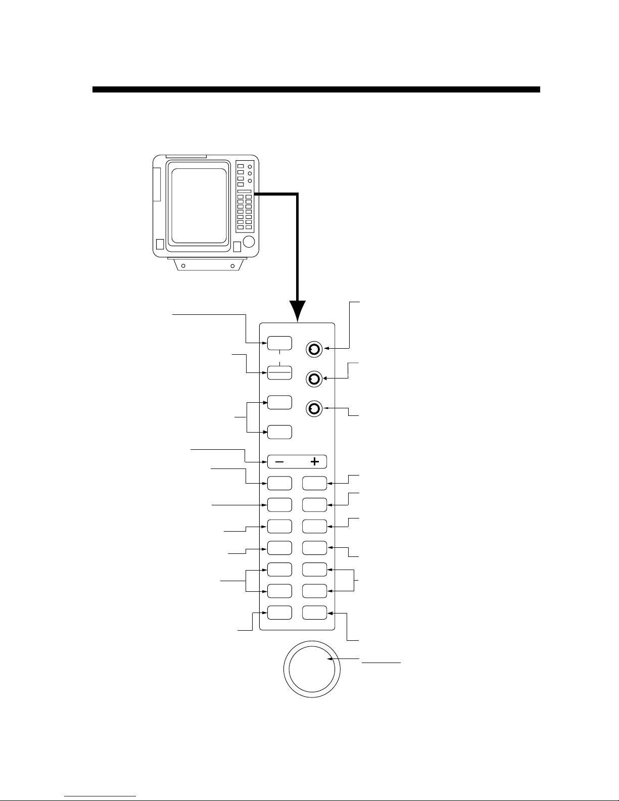
1.1 Controls..............................................1-1
1.1.1 Display unit ................................1-1
1.1.2 Remote controller.......................1-2
1.2 Turning the Radar On and Off............1-3
1.2.1 Turning on the radar ..................1-3
1.2.2 Turning off the radar ..................1-3
1.3 Transmitting........................................1-3
1.4 Indications and Markers.....................1-4
1.5 CRT Brilliance ....................................1-4
1.6 Control Panel Illumination..................1-5
1.7 Tuning the Receiver...........................1-6
1.7.1 Automatic tuning........................1-6
1.7.2 Manual tuning ............................1-6
1.8 Selecting a Range..............................1-6
1.9 Selecting Pulselength.........................1-7
1.10 Receiver Sensitivity............................1-7
1.11 Suppressing Sea Returns..................1-7
1.12 Suppressing Precipitation Returns.....1-9
1.13 Presentation Mode.............................1-9
1.14 Menu Overview ................................1-12
1.14.1 Main menu operation...............1-12
1.14.2 OTHERS menu........................1-13
1.15 Radar Interference ...........................1-15
1.16 Erasing the Heading Marker ............1-15
1.17 Measuring the Range.......................1-16
1.17.1 Measuring range by
range rings..............................1-16
1.17.2 Measuring range by cursor......1-16
1.17.3 Measuring range by VRM........1-16
1.17.4 Unit of range measurement
for VRM and cursor.................1-17
1.18 Measuring the Bearing.....................1-17
1.18.1 Measuring bearing by the
cursor.......................................1-17
1.18.2 Measuring bearing by the
EBL.........................................1-17
1.18.3 Displaying true or relative
bearing....................................1-18
1.19 Collision Assessment by the
Offset EBL........................................1-19
1.20 Measuring Range and Bearing
Between Two Targets ...................... 1-20
1.21 Shifting the Picture........................... 1-21
1.22 Zoom................................................ 1-22
1.23 Guard Alarm .................................... 1-23
1.23.1 Selection of guard zone type...1-23
1.23.2 Setting the guard zone............ 1-24
1.23.3 Silencing the aural alarm......... 1-24
1.23.4 Canceling the guard zone
and guard alarm..................... 1-25
1.23.5 Guard alarm sensitivity............ 1-25
1.23.6 Notes on the guard alarm........1-25
1.24 Outputting Cursor Position to
Video Plotter .................................... 1-25
1.25 Echo Trails....................................... 1-26
1.25.1 Selecting trail time................... 1-26
1.25.2 Starting echo trails ..................1-26
1.25.3 Canceling echo trails............... 1-26
1.25.4 Selecting trail gradation........... 1-27
1.26 Echo Stretch.................................... 1-27
1.27 Watchman........................................ 1-28
1.27.1 Turning on watchman..............1-28
1.27.2 Canceling watchman............... 1-28
1.28 Function Keys (F1, F2).................... 1-29
1.28.1 Default settings ....................... 1-29
1.28.2 Programming the function
keys........................................ 1-29
1.29 Displaying Navigation Data ............. 1-30
1.29.1 Turning navigation data
on/off ...................................... 1-30
1.29.2 Turning the waypoint mark
on/off ...................................... 1-31
1.30 Displaying Navigation Data
in Standby........................................ 1-31
1.30.1 Displaying navigation data
in standby............................... 1-31
1.30.2 Notes on navigation data
in standby............................... 1-32
1.31 Parallel Index Lines ......................... 1-32
1.32 Economy Mode................................ 1-32
1.33 Suppressing Noise........................... 1-33
1.34 Suppressing Second-trace Echoes. 1-33
1.35 Brilliance of Characters, Markers .... 1-33
1.36 Cursor Data ..................................... 1-34

iv
1.37 Selecting Ranges to Use................ 1-34
1.38 Position Data.................................. 1-34
1.39 Dead Sector................................... 1-35
2. INTERPRETING THE DISPLAY
2.1 General............................................ 2-1
2.1.1 Minimum and maximum
ranges...................................... 2-1
2.1.2 Radar resolution........................ 2-2
2.1.3 Bearing accuracy ......................2-2
2.1.4 Range measurement.................2-2
2.2 False Echoes.................................... 2-3
2.2.1 Multiple echoes......................... 2-3
2.2.2 Sidelobe echoes........................2-3
2.2.3 Virtual image............................. 2-4
2.2.4 Shadow sectors.........................2-4
2.3 SART (Search and Rescue
Transponder) .................................... 2-5
2.3.1 General procedure for
detecting SART response........ 2-6
2.3.2 General remarks on receiving
SART........................................ 2-6
2.4 Racon (Radar Beacon)..................... 2-8
3. MAINTENANCE, TROUBLESHOOTING
3.1 Maintenance Program ...................... 3-2
3.2 Replacing the Fuse...........................3-2
3.3 Troubleshooting ................................ 3-3
3.3.1 Easy troubleshooting.................3-3
3.3.2 Advanced troubleshooting.........3-4
3.4 Diagnostics....................................... 3-6
3.5 Replacement of Magnetron............... 3-7
MENU TREE................................................ M-1
SPECIFICATIONS ......................................SP-1
INDEX
Declaration of Conformity

v
FOREWORD
A Word to the Owner of the FR-7041R-MARK-2
FURUNO Electric Company thanks you for purchasing the FR-7041R-MARK-2
Marine Radar. We are confident you will discover why the FURUNO name has
become synonymous with quality and reliability.
For over 50 years FURUNO Electric Company has enjoyed an enviable
reputation for quality and reliability throughout the world. This dedication to
excellence is furthered by our extensive global network of agents and dealers.
Your radar is designed and constructed to meet the rigorous demands of the
marine environment. However, no machine can perform its intended function
unless properly installed and maintained. Please carefully read and follow the
operation and maintenance procedures set forth in this manual.
We would appreciate feedback from you, the end-user, about whether we are
achieving our purposes.
Thank you for considering and purchasing FURUNO.
Features
The FR-7041R-MARK-2 has a large variety of functions, all contained in a rugged
case.
All controls respond immediately to the operator’s command and each time a key
is pressed, the corresponding change can be seen on the screen.
The main features of the FR-7041R-MARK-2 are
•Traditional FURUNO reliability and quality.
•High definition 12-inch (30 centimeter) raster-scan display.
•Precision 1.2 meter slotted waveguide antenna capable of withstanding 70
knot wind velocity.
•Eight levels of target quantization for high target definition.
•On-screen alphanumeric readout of all operational information.
•Guard zone alarm watches for targets entering (or exiting) a guard zone.
•Operates on 12-32 V DC power.

vi
•The CRT can be set to turn off automatically during standby to reduce power
consumption.
•Ship’s position in latitude and longitude, ship’s speed, and range and bearing
to a waypoint can be shown in the bottom text area with navigation input in IEC
61162-1 (NMEA 0183) format.
•Remote controller provides armchair control of range, transmission, standby
and off centering.
•Target latitude and longitude position can be output to external equipment.
•Transmission can be prevented in a specific area. Ask you serviceman about
this feature.
•Conforms to
IEC 60936: Shipborne radar performance requirements
IEC 61162-1: Marine navigation and radiocommunication equipment and
systems – Digital interfaces – Part 1: Single talker and multiple
listeners
IEC 60945: General requirements for maritime navigation and
radiocommunication equipment

vii
SYSTEM CONFIGURATION
Antenna Unit
XN12A-RSB-0073-073
Display Unit
RDP-136
RU-3423
100 110
115 220 230 VAC
1φ, 50 60 Hz
12/24-32 VDC
Broken lines denote optional equipment.
Rectifier
Heading Sensor
Navigator
Echo Sounder
External Buzzer
OP03-173
Remote
Controller
RCU-009
Remote
Display
FMD-811
Heading Sensor
Navigator
Echo Sounder

1-1
1. OPERATION
1.1 Controls
1.1.1 Display unit
POWER
F1
F2
BRILL
SHIFT
ZOOM
ECHO
TRAIL
MODE
GUARD
ALARM
EBL
OFFSET
ENTER
NM/KM
VRM 1
MENU
EBL 1
RANGE
OFF
ECONOMY
STBY
T X
GAIN
HM OFF(PUSH)
A/C SEA
ES (PUSH)
FTC (PUSH)
A/C RAIN
Turns power on.
Press together with
[STBY/TX] key to turn power off.
Toggles between standby and
transmit.
Selects radar range.
Adjusts display brilliance.
Control: Adjusts sensitivity of
radar receiver.
Switch: Temporarily erases
heading marker.
Sets/cancels guard alarm;
silences aural alarm.
Measures range and bearing
between two targets;predicts
collision course.
Opens/closes menu.
Displays target movement in
afterglow.
TLL
VRM 2
EBL 2
Turns respective EBL on/off.
Selects presentation mode.
Turns respective VRM on/off.
Trackball
1) Shifts cursor, EBL and VRM.
2) Sets guard zone.
3) Selects items and options
from menus.
Registers selection on menus.
Switches unit of measurement
for VRM and cursor. Outputs cursor position to
navigation device.
Control:Manually suppresses rain clutter.
Switch: Automatic rain clutter
suppression.
Control:Suppresses sea clutter.
Switch: Stretches echoes in bearing
direction (ES1) and bearing
and range directions (ES2).
Touch-and-release: Shift
Long press: Zoom
Executes function programmed.
Figure 1-1 Control panel

1. OPERATION
1-2
1.1.2 Remote controller
The remote controller provides control of offcenter, standby, transmit and range
functions.
OFF
CENTER
RANGE
ST BY
TX
Sweep center moves to
stern direction 30%
(offcenter).
Toggles standby, transmit.
Selects radar range.
Figure 1-2 Remote controller

1. OPERATION
1-3
DANGER
Make sure no one is in the
vicinity of the antenna unit
before turning on the radar.
Serious injury or death can
result if someone is struck
by the rotating antenna.
1.2 Turning the Radar On and Off
1.2.1 Turning on the radar
Press the [POWER] switch. The control panel lights and a timer displays the time
remaining for warm up of the magnetron, counting down from 1:30 to 0:01.
Further, the bearing scale, range, range ring interval, pulselength, and
presentation mode are displayed.
1.2.2 Turning off the radar
Press [POWER] and [STBY/TX] together.
Quick Start
Provided that the radar was once in use
with the transmitter tube (magnetron) still
warm, you can turn on the radar into
TRANSMIT status without the one minute
and 30-second standby. If the power switch
has been turned off by mistake and you want
to restart the radar promptly do the following:
1. Press the [POWER] switch not later than
five seconds after power-off.
2. After ST-BY appears, press the
[STBY/TX] key. The radar is restored
to full operation.
1.3 Transmitting
After the power is turned on and the
magnetron has warmed up, ST-BY
(Stand-By) appears at the screen
center. In standby the radar is
available for use at anytime - but no
radar waves are being transmitted.
Press the [STBY/TX] key (display unit
or remote controller) to transmit.
When the radar is transmitting, any echoes from targets appear on the display.
This radar displays echoes in eight intensity levels according to echo strength.
When you won’t be using the radar for an extended period, but you want to keep
it in a state of readiness, place it in standby by pressing the [STBY/TX] key. This
will help extend the life of the magnetron.

1. OPERATION
1-4
1.4 Indications and Markers
HDG 234.5˚
HUP RM
SP
. 125KM
0.025 TRAIL
30min
ZOOM
ES1
AUTO
25 : 38 G (OUT)
IR2
VRM
0.100KM
0.048KM
223.0˚R 0.105KM
EBL/PI
345.6˚R
23.0 R
˚
NR
2ND
ECHO
Parallel index line
Note:
EBL2 and VRM2
indications shown in reverse
video when parallel index
lines are on.
Tuning status
(AUTO or MANUAL)
Echo trail time
Guard zone G(OUT)
or G(IN)
ZOOM or
OFFCENTER
Echo stretch
EBL2
Range ring
VRM2
North marker
Interference rejector
VRM2 range
VRM1 range
Cursor range
Cursor bearing
EBL2 bearing
EBL1 bearing
VRM1
EBL1
Guard zone area
Cursor
Presentation mode
Range ring interval
Range
Echo trail elapsed time
Heading (requires heading data)
Heading marker
Noise rejector
Second-trace echo
rejector
Parallel
Index lines
Tuning bar
FTC
Automatic rain
clutter suppressor
Pulselength
Figure 1-3 Indications and markers
1.5 CRT Brilliance
The [BRILL] key adjusts the brilliance of the display in sixteen levels (1: dimmest,
16: maximum). Each time the key is pressed the newly selected brilliance
appears momentarily at the top of the display for your confirmation.

1. OPERATION
1-5
1.6 Control Panel Illumination
You may adjust the illumination for the control panel as follows.
1. Press the [MENU] key to show the main menu.
INDEX
LINE DISP
DATA
OTHER
MENU
Change brill
from 3 to max.
INT
REJECT
u
Sel byT-ball & press ENTER.
u
RINGS
Figure 1-4 Main menu
2. Operate the trackball to select OTHER MENU and press the [ENTER] key.
[OTHERS]
Select item by T-ball
and press ENTER key.
1. Panel Dimmer
2 . Mark Brill
3 . HD Mark
4 . Characters
5 . Trail Tone
6 . Pulselength
7 . Noise Reject
8 . Trail Time
9 . Tune
10. WPT Mark
11. EBL Ref
12. VRM Unit
13. Watchman
14. STBY Disp
15. Guard Mode
16. Own Position
17. Cursor Posi
18. Alm Sense LV
19. Dead Sector
20. Range
21. 2nd Echo Rej
22. Test
23. Installation Setup
4
4
4
4
20min
1
1
1
1
Single
Short
Off
15sec
Auto
Off
Rel
nm
Off
Norm
In
L/L
R/B
Low
Off
1/8
1/4
Off
2
2
2
2
Multi
Long
On
30sec
Manual
On
True
km
5min
Econo
Out
TD
L/L
Med
On
On
1
1.5
1/2
3/4
3min 6min 15min 30min Cont
2
3
4
6
8
12
16
24 32
TX
3
3
3
3
1min
sm
10min 20min
Nav
Hig
Figure 1-5 OTHERS menu
3. Use the trackball to select “1. Panel Dimmer” followed by level desired.
4. Press the [ENTER] key.
5. Press the [MENU] key to close the menu.

1. OPERATION
1-6
1.7 Tuning the Receiver
The radar receiver can be tuned automatically or manually, and the default tuning
method is automatic.
1.7.1 Automatic tuning
In automatic tuning, the radar is automatically tuned every time the radar is
switched to transmit. The tuning indicator and the indication AUTO at the top right
corner show the tuning circuit is working. Generally, the longer the tuning bar the
better the tuning condition, however the length of the bar changes with number of
radar echoes, range and other factors. The receiver may become detuned in
automatic tuning. To re-tune, press the [STBY/TX] key twice.
HDG 234.5˚
HUP RM
SP
. 125KM
0.025
Tuning bar
AUTO
Tuning method
(AUTO or MANUAL)
Figure 1-6 Tuning bar
1.7.2 Manual tuning
If you require manual tuning do the following:
1. Press the [MENU] key to display the main menu.
2. Use the trackball to select OTHER MENU and press the [ENTER] key.
3. Use the trackball to select the item “9. Tune.”
4. Select the option Manual followed by the [ENTER] key.
5. While pressing and holding down the [GAIN] control, operate the trackball to
show the longest tuning bar possible.
6. Press the [MENU] key to close the menu.
1.8 Selecting a Range
The range selected automatically determines the range ring interval, the number
of range rings and pulse repetition rate, for optimal detection capability in short to
long ranges. You can select which ranges and pulselength (for 3 and 6 kilometer
ranges) to use through the OTHER menu. The range, range ring interval and
pulselength appear at the top left-hand corner of the display for your confirmation.
Press the [RANGE] key. Each time the range is changed the newly selected
range appears momentarily at the center of the display for your confirmation.
Range is always displayed at the top left corner on the screen.

1. OPERATION
1-7
1.9 Selecting Pulselength
The pulselength in use is displayed at the upper left corner of the display.
Appropriate pulselengths are preset to individual range scales and function keys.
Therefore, you are not usually required to select them. If you are not satisfied with
the current pulselength setting, however, it is possible to change it for the 3 and 6
kilometer ranges as below. Generally, select a long pulse for longer detection
range and short pulse for better range discrimination.
1. Press the [MENU] key to show the main menu.
2. Use the trackball to select OTHER MENU and press the [ENTER] key.
3. Use the trackball to select the item “6. Pulselength.”
4. Use the trackball to select pulselength desired (SHORT or LONG) and press
the [ENTER] key.
5. Press the [MENU] key to close the menu.
Range 3 nm 6 nm
Long MP LP
Short SP MP
1.10 Receiver Sensitivity
The [GAIN] control adjusts the sensitivity of the receiver. It works in precisely the
same manner as the volume control of a broadcast receiver, amplifying the
signals received.
The proper setting is such that the background noise is just visible on the screen.
Adjust the sensitivity on the highest range; the background noise is clearer on
that range. If you set up for too little sensitivity, weak echoes may be missed. On
the other hand excessive sensitivity yields too much background noise; strong
targets may be missed because of the poor contrast between desired echoes and
the background noise on the display.
1. Transmit on long range.
2. Adjust the [GAIN] control so background noise is just visible on the screen.
1.11 Suppressing Sea Returns
Echoes from waves can be troublesome, covering the central part of the display
with random signals known as sea clutter. The higher the waves, and the higher
the antenna above the water, the further the clutter will extend. Sea clutter
appears on the display as many small echoes which might affect radar
performance. (See the left-hand figure in Figure 1-7.) When sea clutter masks the
picture, adjust the [A/C SEA] control to reduce the clutter.

1. OPERATION
1-8
The [A/C SEA] control reduces the amplification of echoes at short ranges (where
clutter is the greatest) and progressively increases amplification as the range
increases, so amplification will be normal at those ranges where there is no sea
clutter.
The proper setting of the [A/C SEA] control should be such that the clutter is
broken up into small dots, and small targets become distinguishable.
If the A/C SEA is too low, targets will be hidden in the clutter, while if it is set too
high, both sea clutter and targets will disappear from the display. In most cases
adjust the control until clutter has disappeared to leeward, but a little is still visible
windward.
1. Confirm that the sensitivity is properly adjusted, and then transmit on short
range.
2. Adjust the [A/C SEA] control so small targets are distinguishable but some
clutter remains on the display.
Sea clutter at
display center A/C SEA control adjusted;
sea clutter suppressed
Figure 1-7 Sea clutter
Tip for adjustment the A/C SEA
A common mistake is to over-adjust the circuit so all the clutter is removed. As an
example set up for maximum A/C SEA. You will see how the center of the display
becomes dark. This dark zone can be dangerous (targets may be missed),
especially if the sensitivity is not properly adjusted. Always leave a little clutter
visible on the display to be sure weak echoes will not be suppressed. If there is
no clutter visible on the display, turn off the circuit.
A/C SEA may erase weak echoes.
CAUTION

1. OPERATION
1-9
1.12 Suppressing Precipitation Returns
The vertical beamwidth of the antenna is designed to see surface targets even
when the ship is rolling. However, by this design the unit will also detect rain
clutter (rain, snow, hail, etc.) in the same manner as normal targets. Figure 1-8
shows the appearance of rain clutter on the display.
When rain clutter masks echoes over a wide range, raise the A/C RAIN
setting slightly to distinguish targets from the clutter.
In heavy storms or partial clutter, push in the [A/C RAIN] control to activate the
FTC circuit. This circuit splits up unwanted echoes into a speckled pattern to
distinguish solid targets from the clutter. “FTC” appears at the bottom left corner
of the screen when the FTC circuit is active. Turn off the FTC when its use is not
required so that weak echoes will not be missed.
Appearance of
rain clutter A/C RAIN control adjusted
rain clutter suppressed
Figure 1-8 Rain clutter
1.13 Presentation Mode
Use the [MODE] key to select the presentation mode among head-up, course-up,
north-up and true motion.
When the heading signal is lost the
presentation mode automatically becomes
head-up and the HDG readout shows
xxx.x. Restore the heading signal, and
then press the [MODE] key to display the
heading readout.
Loss of Heading Signal

1. OPERATION
1-10
Presentation mode,
representative display Description
Head-up Mode (HUP RM)
A display without azimuth stabilization in which
the line connecting the center with the top of the
display indicates own ship's heading.
The target pips are painted at their measured dis-
tances and in their directions relative to own ship's
heading.
A short line on the bearing scale is the north marker
indicating compass north. A failure of the heading
sensor will cause the north marker to disappear and
the HDG readout to show xxx.x. After restoring the
heading signal press the [MODE] key to display
the heading.
Heading
marker
North
marker
North-up Mode (NUP RM)
In the north-up mode, target pips are painted at their
measured distances and in their true (heading sensor)
directions from own ship, north being maintained
up of the screen.The heading marker changes its
direction according to the ship's heading.
If the heading sensor fails, the presentation mode
changes to head-up and the north marker disappears.
Also, the HDG readout shows xxx.x. Restore the
heading signal, and then press the [MODE] key to
display the heading readout.
Heading
marker
North
Figure 1-9a Presentation modes

1. OPERATION
1-11
Presentation mode,
representative display Description
Course-up Mode (CUP TM)
An azimuth stabilized display in which a line connect-
ing the center with the top of the display indicates own
ship's intended course (namely, own ship's previous
heading just before this mode has been selected).
Target pips are painted at their measured distances
and in their directions relative to the intended course
which is maintained at the top of screen while the
heading line moves in accordance with ship's yawing
and course changes.This mode is useful to avoid
smearing of picture during course change.
North
marker
Heading
marker
True Motion Mode (NUP TM)
Own ship and other moving objects move in accord-
ance with their true courses and speeds. In ground
stablized TM, all fixed targets, such as landmasses,
appear as stationary echoes.In the sea stablized TM
without set and drift input, the landmass can move on
the screen.
When own ship reaches a point corresponding to
75% of the radius of the display, the own ship is
automatically reset to a point of 50% radius opposite
to the extension of the heading line passing through
the display center. Resetting can be made at any
moment before the ship reaches the limit by pressing
the [SHIFT] key. Automatic resetting is preceded by a
beep sound.
If the heading sensor fails, the presentation mode is
changed to the head-up mode and the north marker
disappears.The HDG readout at the top of the
screen shows xxx.x.Restore the heading signal, and
then press the [MODE] key to display the heading.
North
marker Heading
marker
Figure 1-9b Presentation modes
Table of contents
Other Furuno Marine Radar manuals

Furuno
Furuno FAR-2218 Manual

Furuno
Furuno FAR-1416 User manual

Furuno
Furuno DRS4D User manual

Furuno
Furuno NAVnet 1722 User manual

Furuno
Furuno FELCOM 15 User manual

Furuno
Furuno 1935DISP User manual

Furuno
Furuno FAR-2228 User manual

Furuno
Furuno 841 MARK-2 User manual

Furuno
Furuno FAR-2805 Series User manual

Furuno
Furuno FAR-1513-BB User manual

Furuno
Furuno 1621 MARK-2 User manual

Furuno
Furuno FR-8045 User manual

Furuno
Furuno FR-8062 User manual

Furuno
Furuno FR-8122 User manual

Furuno
Furuno FR-8300DS User manual

Furuno
Furuno FR-7040D User manual

Furuno
Furuno FR-1460DS User manual

Furuno
Furuno FAR-1513 User manual

Furuno
Furuno FR-2165DS User manual

Furuno
Furuno FR-1505 User manual