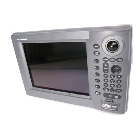
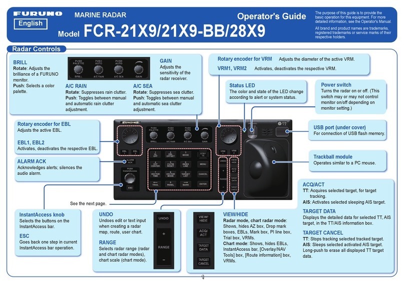
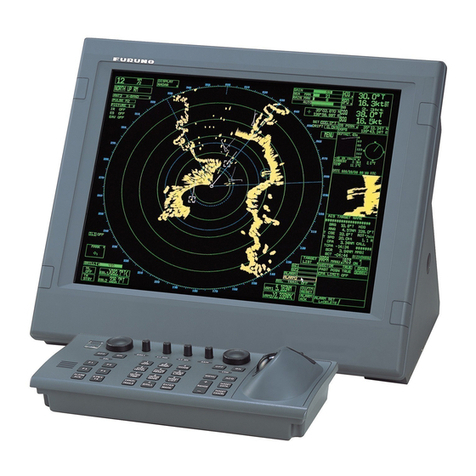
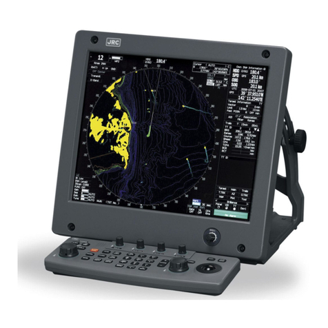
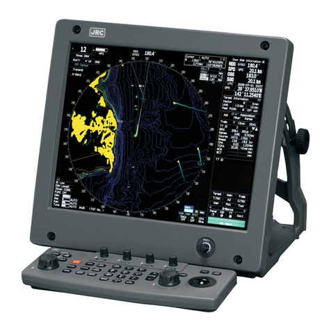
Furuno NAVnet 1722C User manual

MARINE RADAR
MODEL1722/1732/1742/1762
MODEL1722C/1732C/1742C/1762C

C
9-52, Ashihara-cho,
Nishinomiya, Japan
Telephone: 0798-65-2111
Telefax: 0798-65-4200
Your Local Agent/Dealer
All ri
g
hts reserved.
PUB. No. OME-34940
MODEL1722/C SERIES
(
DAMI
)
FIRST EDITION : APR. 2001
D : OCT. 11, 2001
Printed in Japan

i
SAFETY INSTRUCTIONS
WARNING
Do not disassemble or modify the
equipment.
Fire, electrical shock or serious injury can
result.
Immediately turn off the power at the
switchboard if the equipment is emitting
smoke or fire.
Continued use of the equipment can cause
fire or electrical shock. Contact a FURUNO
agent for service.
Keep heater away from equipment.
A heater can melt the equipment's power
cord, which can cause fire or electrical
shock.
Use the proper fuse.
Fuse rating is shown on the equipment.
Use of a wrong fuse can result in damage
to the equipment.
ELECTRICAL SHOCK HAZARD
Do not open the equipment.
Only qualified personnel
should work inside the
equipment.
CAUTION
A warning label is attached to the equip-
ment. Do not remove the label. If the
label is missing or damaged, contact
a FURUNO agent or dealer about
replacement.
WARNING
To avoid electrical shock, do not
remove cover. No user-serviceable
parts inside.
Name:WarningLabel(1)
Type:86-003-1011-0
CodeNo.:100-236-230
WARNING
Radio Frequency
Radiation Hazard
The radar antenna emits electromagnetic
radio frequency (RF) energy which can be
harmful, particularly to your eyes. Never
look directly into the antenna aperture from
a close distance while the radar is in
operation or expose yourself to the trans-
mitting antenna at a close distance.
Distances at which RF radiation levels of
100 and 10 W/m
2
exist are given in the
table below.
Note: If the antenna unit is installed at a
close distance in front of the wheel house,
your administration may require halt of
transmission within a certain sector of
antenna revolution. This is possible - Ask
your FURUNO representative or dealer to
provide this feature.
MODEL Distance to
100W/m2
point
Distance to
10W/m2
point
1722 Nil Worst case
0.50 m
1732
1742
1762 0.20 m
Nil Worst case
0.50 m
Nil Worst case
1.00 m
Worst case
3.00 m
No one navigation device should ever be
solely replied upon for the navigation of
a vessel.
Always confirm position against all available
aids to navigation, for safety of vessel and
crew.
CAUTION

ii
TABLE OF CONTENTS
TABLE OF CONTENTS ........................................................................................ii
FOREWORD.......................................................................................................viii
SYSTEM CONFIGURATIONS...............................................................................x
1. OPERATIONAL OVERVIEW.........................................................................1-1
1.1 Operating Controls ....................................................................................................1-2
1.1.1 Display unit controls........................................................................................1-2
1.1.2 Remote controller............................................................................................1-5
1.2 Inserting a Chart Card...............................................................................................1-6
1.3 Turning the Unit On/Off..............................................................................................1-7
1.4 Cursor Pad, Cursor....................................................................................................1-8
1.5 Display Brilliance, Panel Brilliance, Contrast, Hue.....................................................1-9
1.5.1 Display brilliance, panel brilliance....................................................................1-9
1.5.2 Contrast ........................................................................................................1-10
1.5.3 Hue (MODEL1722C series)...........................................................................1-10
1.6 Selecting a Display.................................................................................................. 1-11
1.6.1 Display modes .............................................................................................. 1-11
1.6.2 Selecting a display........................................................................................1-12
1.6.3 Switching control in combination and overlay screens...................................1-13
1.6.4 Selecting radar source..................................................................................1-14
1.7 Data Boxes..............................................................................................................1-15
1.7.1 Showing, hiding data boxes with soft key......................................................1-15
1.7.2 Rearranging data boxes................................................................................1-15
1.7.3 Temporarily erasing a data box .....................................................................1-15
1.8 Function Keys.......................................................................................................... 1-16
1.8.1 Executing a function......................................................................................1-16
1.9 Simulation Display...................................................................................................1-17
2. RADAR OPERATION....................................................................................2-1
2.1 Radar Display............................................................................................................2-1
2.2 Transmitting, Stand-by...............................................................................................2-2
2.3 Tuning .......................................................................................................................2-2
2.4 Adjusting the Gain.....................................................................................................2-2
2.5 Reducing Sea Clutter.................................................................................................2-4
2.5.1 How the A/C SEA works.................................................................................. 2-4
2.5.2 Adjusting A/C SEA ..........................................................................................2-4
2.6 Reducing Precipitation Clutter ...................................................................................2-5
2.6.1 Adjusting the A/C RAIN...................................................................................2-5
2.6.2 Adjusting the FTC ...........................................................................................2-6
2.7 Range Scale..............................................................................................................2-7
2.8 Pulselength................................................................................................................2-8

iii
2.9 Presentation Mode.....................................................................................................2-9
2.9.1 Selecting a presentation mode ........................................................................2-9
2.9.2 Description of presentation modes.................................................................2-10
2.10 Measuring the Range...............................................................................................2-12
2.10.1Measuring range by range rings....................................................................2-12
2.10.2Measuring range by cursor............................................................................2-13
2.10.3Measuring range by VRM..............................................................................2-14
2.10.4Erasing a VRM, VRM indication.....................................................................2-15
2.10.5Erasing EBL/VRM data boxes .......................................................................2-15
2.10.6Hiding EBL/VRM data boxes .........................................................................2-15
2.10.7Moving EBL/VRM data boxes........................................................................2-15
2.11 Measuring the Bearing.............................................................................................2-15
2.11.1 Measuring bearing by cursor .........................................................................2-15
2.11.2 Measuring bearing by EBL ............................................................................2-15
2.11.3 Erasing an EBL, EBL indication.....................................................................2-16
2.11.4 Erasing EBL/VRM data boxes .......................................................................2-16
2.11.5 Hiding EBL/VRM data boxes .........................................................................2-16
2.11.6 Moving EBL/VRM data boxes........................................................................2-16
2.12 Erasing the Heading Line, North Marker ..................................................................2-17
2.13 Reducing Noise........................................................................................................2-17
2.14 Reducing Radar Interference...................................................................................2-18
2.15 Zoom .......................................................................................................................2-19
2.15.1Zooming in on radar targets...........................................................................2-19
2.15.2Zooming ARP, TTM targets............................................................................2-19
2.16 Shifting the Picture...................................................................................................2-20
2.16.1Manual shift...................................................................................................2-20
2.16.2Automatic shift...............................................................................................2-21
2.17 Using the Offset EBL................................................................................................2-22
2.17.1Predicting a collision course..........................................................................2-22
2.17.2Measuring range & bearing between two targets...........................................2-23
2.18 Echo Trails...............................................................................................................2-24
2.18.1Trail time........................................................................................................2-24
2.18.2Starting echo trails.........................................................................................2-25
2.18.3Trail brilliance (MODEL1722 series) ..............................................................2-25
2.18.4Trail gradation (MODEL1722C series)...........................................................2-25
2.18.5Trail color (MODEL1722C series)..................................................................2-26
2.19 Echo Stretch ............................................................................................................2-27
2.20 Echo Averaging........................................................................................................2-28
2.21 Outputting TLL Data.................................................................................................2-29
2.22 GuardAlarm.............................................................................................................2-30
2.22.1Setting a guard alarm zone............................................................................2-30
2.22.2When the alarm is violated….........................................................................2-31
2.22.3Canceling the guard alarm.............................................................................2-31
2.23 Watchman................................................................................................................2-32
2.23.1How watchman works....................................................................................2-32
2.23.2Turning on/off watchman ...............................................................................2-32
2.23.3Setting watchman stand-by interval...............................................................2-32
2.24 Waypoint Marker......................................................................................................2-33
This manual suits for next models
19
Table of contents
Other Furuno Marine Radar manuals

Furuno
Furuno FR-604D User manual

Furuno
Furuno FR-2855 User manual

Furuno
Furuno FELCOM 15 User manual

Furuno
Furuno 1931 User manual

Furuno
Furuno FAR-2318 User manual

Furuno
Furuno FCR-2107 series User manual

Furuno
Furuno FELCOM 12 User manual

Furuno
Furuno 1931 User manual

Furuno
Furuno 1815 User manual

Furuno
Furuno 1731 MARK 3 User manual
Furuno
Furuno FR-602D User manual

Furuno
Furuno 841 MARK-2 User manual

Furuno
Furuno FR-7100D User manual

Furuno
Furuno FAR-2167DS-BB User manual

Furuno
Furuno FR-2155 User manual

Furuno
Furuno 1715 User manual

Furuno
Furuno FR-2110 Operators User manual

Furuno
Furuno FCR-902 User manual

Furuno
Furuno 1823C User manual

Furuno
Furuno 1715 User manual