ii
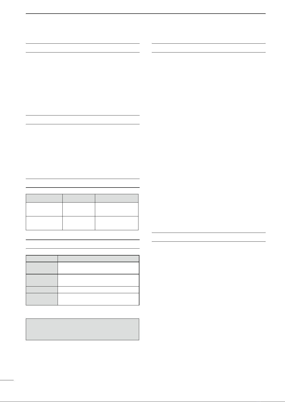
For radar unit:
R
WARNING! NEVER let metal, wire or other
objects touch any internal part or terminals of the radar
unit. This may result in an electric shock.
R
WARNING! NEVER apply AC voltage to the
DC input terminals of the radar unit. This may pose a
fire hazard, result in an electric shock or damage the
radar unit.
R
WARNING! NEVER apply more than 32 V DC
to the DC input terminal of the radar unit. This may
pose a fire hazard or damage the radar unit.
R
WARNING! NEVER touch the radar unit with
wet hands.This may result in an electric shock or dam-
age the radar unit.
R
WARNING! NEVER open the bottom cover of
the radar unit. There are no user adjustment points.
This may result in an electric shock and incorrect reas-
sembly may cause a fire hazard.
CAUTION: NEVER connect the radar unit to a DC
power source using reverse polarity. This will damage
the radar unit.
CAUTION: NEVER remove the fuse holder from
the DC power cable. This will damage the radar unit.
DO NOT place the radar unit in excessively dusty
environments.
DO NOT place the radar unit near heating equip-
ment or in direct sunlight or where hot or cold air blows
directly onto it.
DO NOT use or place the radar unit in areas with tem-
perature below –20˚C (–4˚F) or above +60˚C (+140˚F).
DO NOT use chemical agents such as benzine or
alcohol when cleaning the radar unit, as they can
damage the radar unit’s surfaces.
DO NOT place the radar unit in areas that will block
air passage or put anything around the radar unit. This
will obstruct heat dissipation.
KEEP the radar unit out of the reach of children.
KEEP the radar unit away from heavy rain, and never
immerse it in the water.
The radar unit meets IPX4 requirements for splash re-
sistance when the supplied connection cable, scanner
unit are connected.
However, if it is dropped, splash resistance cannot be
guaranteed because of possible damage to the case
or the waterproof seals.
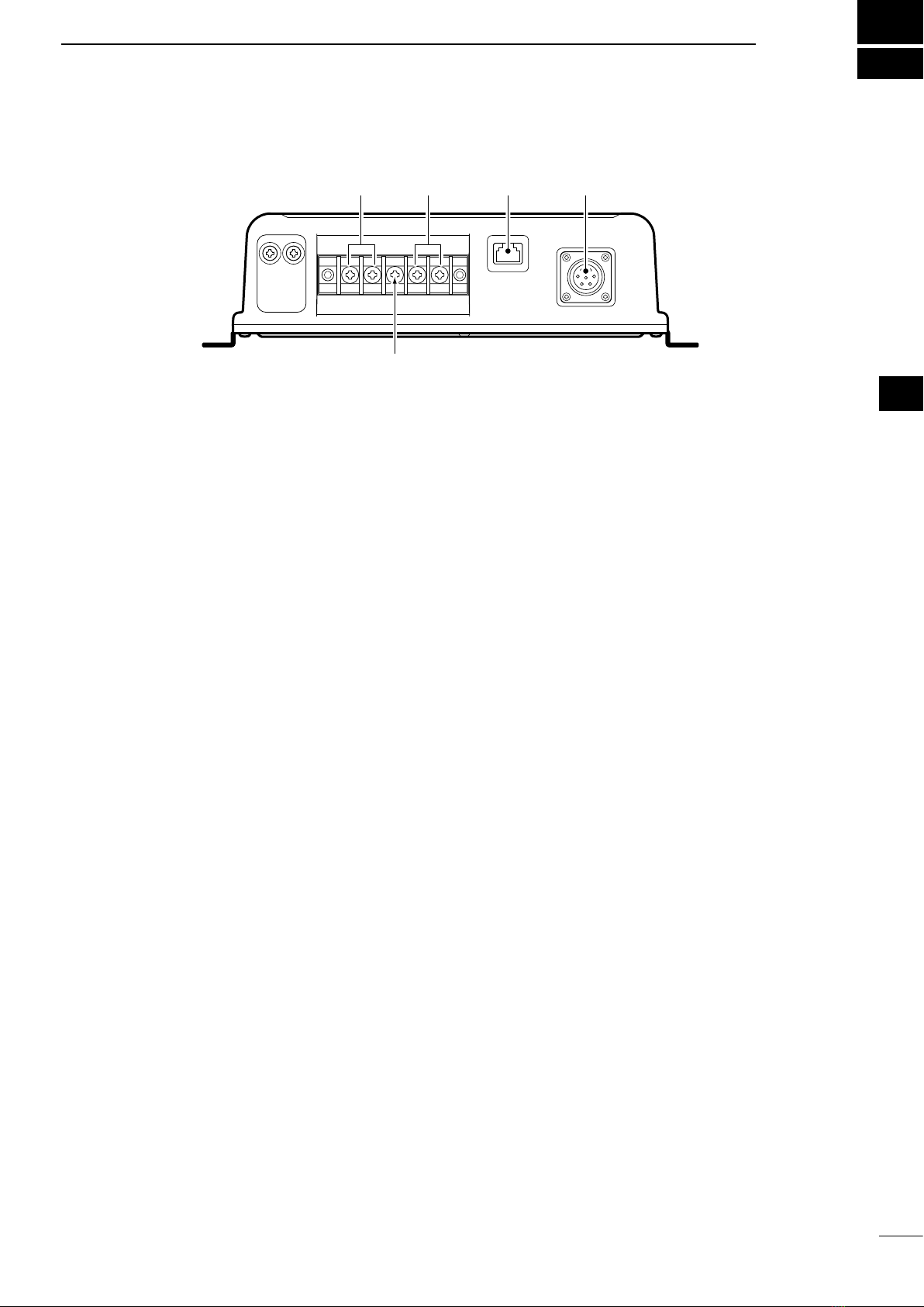
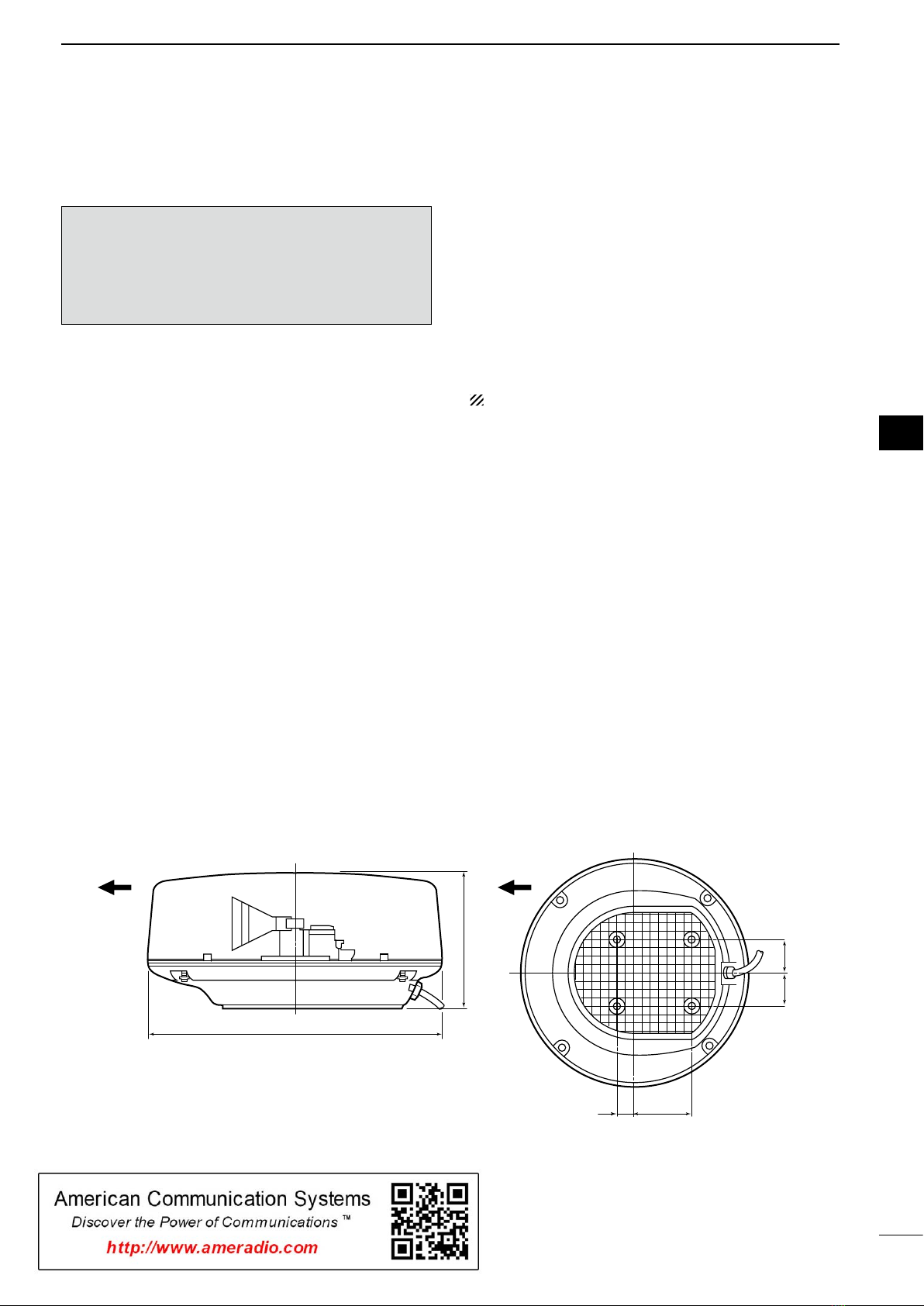
For Scanner unit:
R
DANGER: HIGH VOLTAGE! NEVER open
the scanner unit. The scanner unit contains high volt-
age that could be fatal. And there are no user adjust-
ment points. All repairs and adjustments MUST be
made by a qualified electronics technician at your
Marine Navigation Dealer.
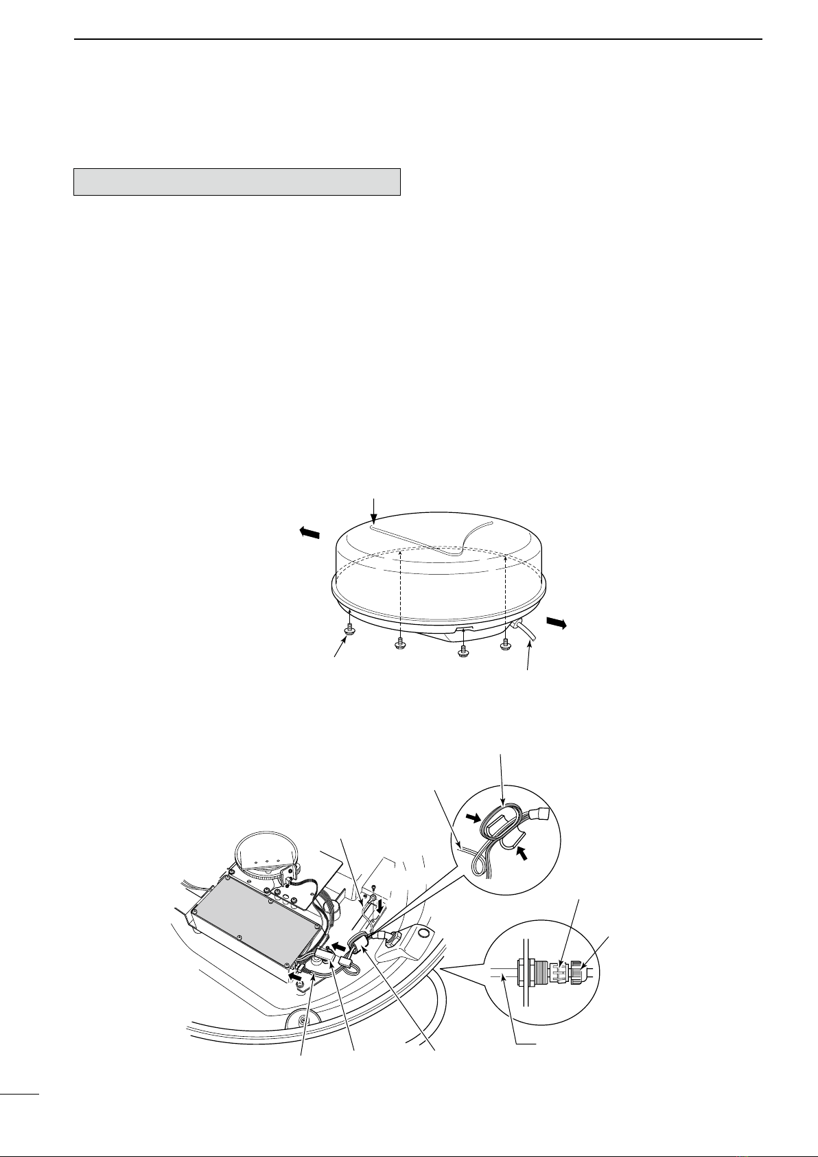
For qualified electronics technician only:
R
DANGER: HIGH VOLTAGE! High volt-
ages of up to 3,500 volts are used in the scanner
unit. Although prudent measures for safety have
been adopted, sufficient care must be taken in
the operation, maintenance and adjustment of the
scanner unit.
Electric shock of 1,000 volts or more may cause
electrocution and death; even an electric shock of
only 100 volts may be fatal.
R DANGER: HIGH VOLTAGE! To prevent an
electric shock, turn the radar’s power is OFF*1and
do not reach inside the scanner unit until you have:
• discharged the capacitors by disconnecting the system
cable from the radar unit for 5 min.
• checked that no electric charges remain inside the de-
vice.
Also, it is safest to wear dry insulated rubber gloves.
NEVER use both hands simultaneously; keep one
hand in your pocket.
R
WARNING: RADIATION HAZARD!
Radiation emitted from the scanner unit can be
harmful, particularly to the eyes. To avoid harm-
ful radiation, turn
the radar’s power is OFF*1
before
beginning work on the scanner unit.
DO NOT use or place the scanner unit in areas with
temperature below –25˚C (–13˚F) or above +70˚C
(+158˚F).
NEVER immerse the scanner unit in the water.
The scanner units meet IPX6
*2
requirements for high-
pressure water jet resistance.
However, if these items are dropped, high-pressure
water jet resistance cannot be guaranteed because
of possible damage to the cases or the waterproof
seals.
*1
The radar’s power automatically turns OFF approx. 30 sec.
after the display units’ power are turned OFF.
*2
Except for the cable connectors. They meet IPX4 require-
ments while connecting to the radar unit.
For U.S.A. only
CAUTION: Changes or modifications to this radar,
not expressly approved by Icom Inc., could void your
authority to operate this device under FCC regulations.
PRECAUTIONS