Furuno FA-150 User manual

www.furuno.com
A
ll brand and product names are trademarks, registered trademarks or service marks of their respective holders.
Installation Manual
U-AIS TRANSPONDER
Model FA-150
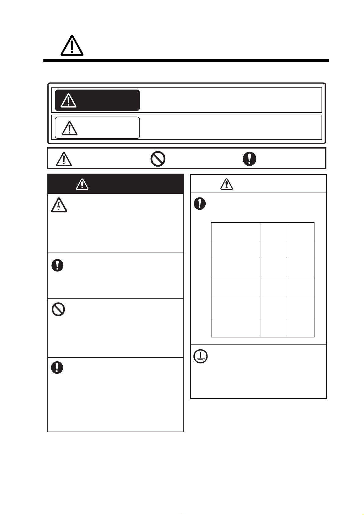
SAFETY INSTRUCTIONS ................................................................................................ i
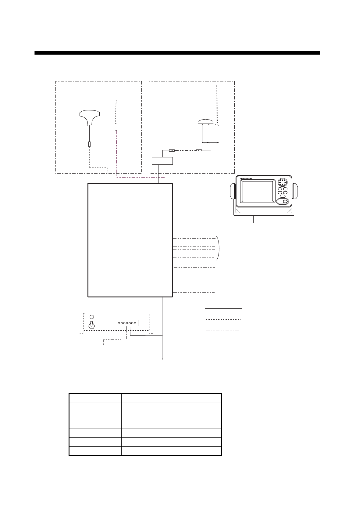
SYSTEM CONFIGURATION ........................................................................................... ii
EQUIPMENT LISTS........................................................................................................ iii
1. MOUNTING..............................................................................................................1-1
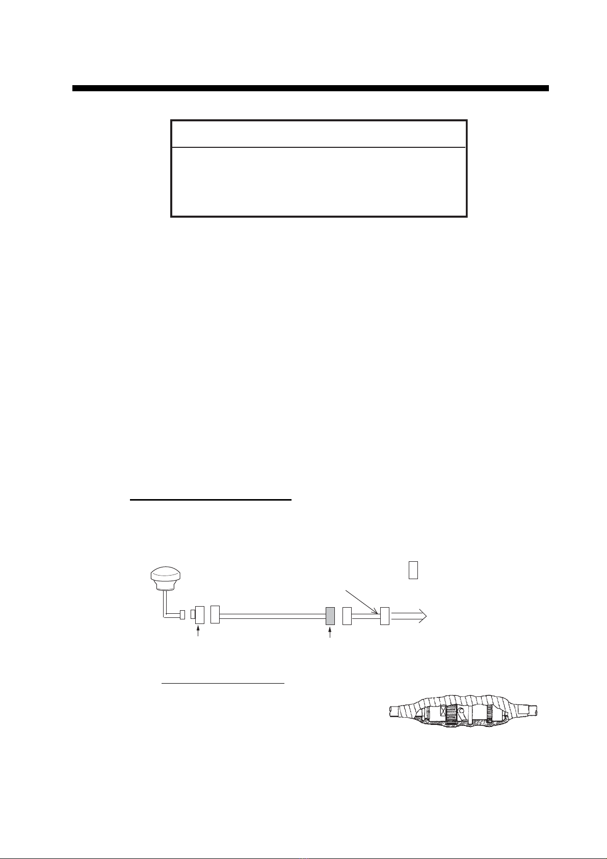
1.1 Antenna Units ....................................................................................................................1-1
1.2 Monitor Unit........................................................................................................................1-7
1.3 UAIS Transponder .............................................................................................................1-9
1.4 Power Supply (option)......................................................................................................1-10
1.5 Pilot Plug (option).............................................................................................................1-10
2. WIRING....................................................................................................................2-1
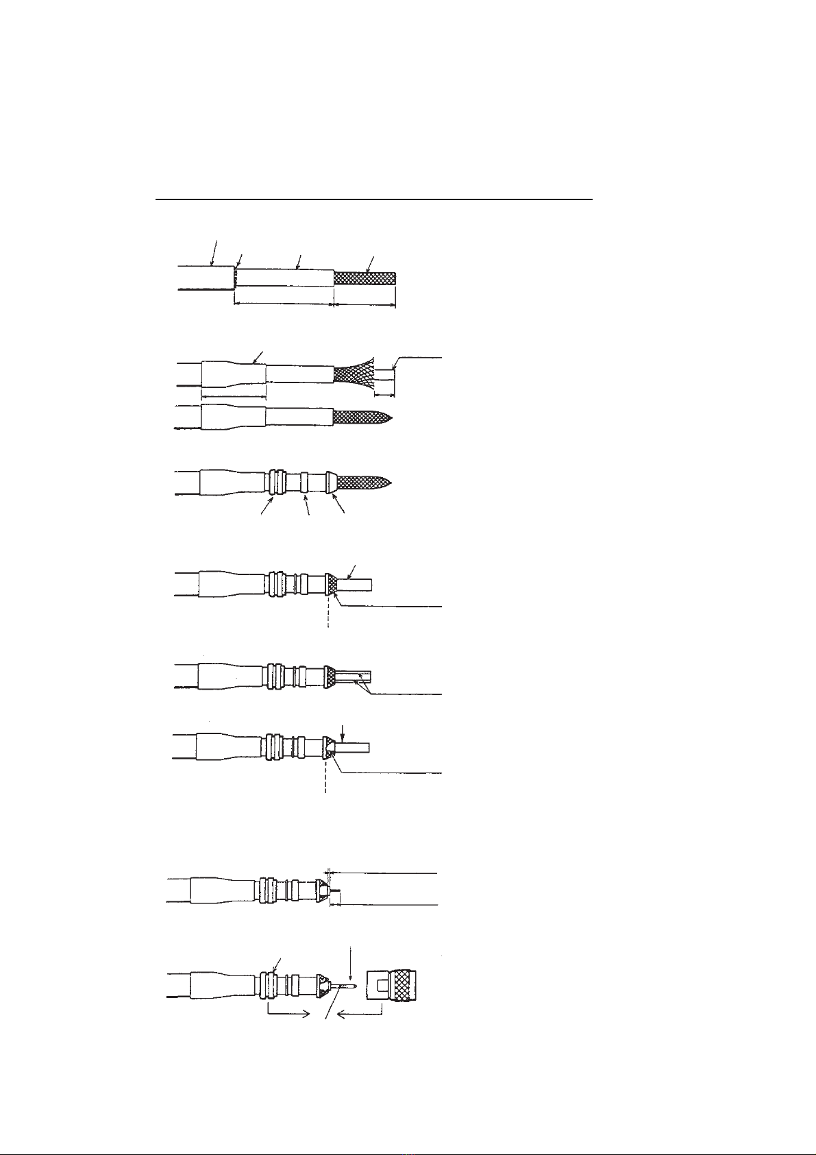
2.1 Connection.........................................................................................................................2-1
2.2 Changing Ship’s Mains Specifications...............................................................................2-4
3. SETTING AND ADJUSTMENT ...............................................................................3-1
3.1 Inland AIS Specific Settings...............................................................................................3-1
3.2 How to Set MMSI, IMO No., Name and Call Sign..............................................................3-4
3.3 How to Set GPS Antenna Position.....................................................................................3-5
3.4 How to Set Ship Type ........................................................................................................3-6
3.5 How to Set I/O Port............................................................................................................3-6
3.6 How to Set Long Range Channel ....................................................................................3-10
4. ATTACHING LAN KIT (OPTION)............................................................................4-1
5. IEC 61162-1/2 DATA SENTENCES ........................................................................5-1
APPENDIX 1 JIS CABLE GUIDE .............................................................................AP-1
PACKING LISTS ......................................................................................................... A-1
OUTLINE DRAWINGS ................................................................................................ D-1
INTERCONNECTION DIAGRAM ................................................................................ S-1

The paper used in this manual
is elemental chlorine free.
・FURUNO Authorized Distributor/Dealer
9 52 Ashihara cho,
Nishinomiya, 662 8580, JAPAN
A
:
NOV
2004
.
Printed in Japan
All rights reserved.
K
:
SEP
.
09, 2015
Pub. No.
IME-44310-K
(
AKMU
)
FA-150
0 0 0 1 5 0 0 8 3 1 9

i
SAFETY INSTRUCTIONS
The installer must read the safety instructions before attempting to install this equipment.
WARNINGWARNING
Be sure that the power supply is
compatible with the voltage rating of the
equipment.
Connection of an incorrect power supply
can cause fire or damage the equipment.
The voltage rating of the equipment
appears on the label above the power
connector.
CAUTIONCAUTION
GVA-100
DB-1
PR-240
Indicates a potentially hazardous situation which, if not avoided,
could result in death or serious injury.
Warning, Caution Prohibitive ActionProhibitive Action
Indicates a potentially hazardous situation which, if not avoided,
can result in minor or moderate injury.
WARNING
CAUTION
ELECTRICAL SHOCK HAZARD
Do not open the equipment unless
totally familiar with electrical circuits
and service manual.
Only qualified personnel should work
inside the equipment.
Turn off the power at the switchboard
before beginning the installation.
Fire or electrical shock can result if the
power is left on.
Do not install the equipment where it
may get wet from rain or water
splash.
Water in the equipment can result in
fire, electrical shock or damage the
equipment.
Observe the following compass safe
distances to prevent interference to a
magnetic compass:
Standard
compass
Steering
compass
FA-1501
UAIS Transponder
FA-1502
Monitor unit
1.2 m 0.8 m
0.45 m 0.3 m
0.3 m 0.3 m
0.3 m 0.3 m
0.9 m 0.6 m
Attach securely protective earth to
the ship's body.
The protective earth is required to the
power supply to prevent electrical
shock.

ii
SYSTEM CONFIGURATION
Category of the units
GSC-001 Exposed to the weather
GPA-017S Exposed to the weather
GVA-100 Exposed to the weather
FA-1501 Protected from the weather
FA-1502 Protected from the weather
DB-1 Protected from the weather
PR-240 Protected from the weather
: Standard
: Option
GPS/VHF
combined antenna
GVA-100
GPS antenna
GSC-001
GPA-017S
Distributor unit
DB-1
VHF antenna
Power supply
PR-240
100-115/
200-230 VAC
1
Ø, 50/60Hz
12-24 VDC
: Local supply
Either
24 VDC
MONITOR UNIT
FA-1502
12-24 VDC
UAIS TRANSPONDER
FA-1501 External display, NAVNET2,
Pilot plug unit Sensor
PC, BEACON RECEIVER
Alarm system
UNIVERSAL AIS
STATUS
NAV
FA-150
PWR
DISP DIM
MENU ENT
LAN
Blue Sign

iii
EQUIPMENT LISTS
Standard supply
Name Type Code no. Qty Remarks
UAIS Transponder FA-1501 — 1
Monitor Unit FA-1502 — 1
GPS Antenna GSC-001 — 1
Select one.
GPA-017S — 1
GPS/VHF
Combined Antenna GVA-100 — 1
Distributor Unit DB-1 000-010-591 1
Installation
Materials
MJ-A10SPF0012-
050+ 001-122-900-10 1 Cable for FA-1501
CP24-00501 005-956-010
1
For FA-1501
(Type: 5x20 SUS304, 4 pcs.
Code: 000-162-608-10)
CP24-00400 001-058-240
1
Cable for FA-1502
(Type: MJ-A3SPF0013-035
Code: 000-135-397)
CP14-06001 001-058-230
1
For FA-1502
(Type: 5x20 SUS304, 4 pcs.
Code: 000-162-608-10)
CP24-00101 005-950-730
1
For DB-1
(Type: 4x30 SUS304, 2 pcs.
Code: 000-162-659-10)
CP24-00110 000-053-878 1 For GVA-100
CP24-00502 005-955-560 1 For GPA-017S/GSC-001
Accessories FP14-02801 001-058-250
1
For FA-1502
(Type: 20-022-3017-0
Code: 100-337-240-10)
Spare Parts SP24-00101 001-163-760
1
For FA-1502
(Type: FGBO-A 125V 3A
PBF, 2 pcs. Code: 000-155-
850-10)

EQUIPMENT LISTS
iv
Optional supply
Name Type Code no. Remarks
Monitor unit FA-1502 —
Antenna cable
set
CP20-02700 004-381-160 8D-FB-CV(30m)+CP20-02701
CP20-02720 001-207-990 8D-FB-CV(40m)+CP20-02701
CP20-02710 004-381-170 8D-FB-CV(50m)+CP20-02701
Antenna cable
set
CP24-00300 000-041-938 8D-FB-CV(30m)+CP24-00301
CP24-00320 000-022-637 8D-FB-CV(40m)+CP24-00301
CP24-00310 000-041-939 8D-FB-CV(50m)+CP24-00301
Coaxial cable TNC-PS/PS-3D-L15M-R 000-133-670-12 TNC-TNC, 15m
Mast mount fix-
ture
CP20-01111 004-365-780 For GSC-001/GPA-017S
Right-angle an-
tenna base
No.13-QA330 001-111-910-10 For GSC-001/GPA-017S
L-angle antenna
base
No.13-QA310 001-111-900-10 For GSC-001/GPA-017S
Antenna base for
rail mount
No.13-RC5160 001-111-920-10 For GSC-001/GPA-017S
Whip antenna FAB-151D 001-144-490-10
Whip Antenna
With Bracket
CP05-11001 001-034-670
Antenna Fixing
Bracket
CP05-14001 001-430-360 Bracket M-15AS1
AC-DC power
supply
PR-240 000-013-632 Include installation materials
CP24-00151
Pilot plug OP24-3 000-053-911
AD Converter AD-100 — For gyrocompass
Cable assy. MJ-A10SPF0012-050+ 001-122-900-10 5 m Transponder-display,
connector attached at
one end
MJ-A10SPF0012-100+ 001-122-910-10 10 m
MJ-A10SPF0012-250+ 001-122-930-10 25 m
MJ-A10SPF0012-500+ 001-122-940-10 50 m
MJ-A10SPF0012-1000+ 001-122-920-10 100 m
Flush mount kit S OP20-17 000-040-720 For monitor unit
Flush mount kit F OP20-29 000-041-405
80 Mast mount
kit
OP24-5 005-954-510 For GVA-100
GPS antenna GSC-001-FA-T 000-041-929
LAN kit OP24-8 005-956-020 See page 4-1.
UAIS display
software
FAISPC MARK-2 005-860-470

1-1
1. MOUNTING
1.1 Antenna Units
1.1.1 GPS antenna unit
Install the GPS antenna unit referring to the drawing on page D-5 or D-6 at the back
of this manual. When selecting a mounting location for the antenna, keep in mind the
following points.
• Select a location out of the radar beam. The radar beam will obstruct or prevent re-
ception of the GPS satellite signal.
• There should be no interfering object within the line-of-sight to the satellites. Objects
within line-of-sight to a satellite, for example, a mast, may block reception or prolong
acquisition time.
• Mount the antenna unit as high as possible to keep it free of interfering objects and
water spray, which can interrupt reception of GPS satellite signal if the water freez-
es.
How to extend antenna cable
Three types of antenna cable extensions are optionally available.
a) Antenna cable set CP20-02700
Waterproofing connector
Wrap connector with vulcanizing tape and
then vinyl tape. Bind the tape end with a
cable-tie.
b) Antenna cable set CP20-02720 (8D-FB-CV,
40m)/CP20-02710 (8D-FB-CV, 50m) Con-
nect the cable the same as a) above.
NOTICE
Do not apply paint, anti-corrosive sealant or contact spray
to coating or plastic parts of the equipment.
Those items contain organic solvents that can damage coating
and plastic parts, especially plastic connectors.
Antenna Unit
Antenna Cable
30m 1 m
Fabricate locally. (See next page.)
N-P-8DFB
FA-1501
: Connector
Conversion
Cable Assy.
NJ-JP-3DXV-1
TNCP-NJ
0.6m
Waterproofing connector

1. MOUNTING
1-2
c) Cable type RG-10/UY (shipyard supply)
Note: The length of this cable should be less than 20 m to prevent signal loss. The
coax. coupling cable assy.(type: NJ-TP+3DXV-1, code no. 000-123-809-10), co-
axial connector (N-P-8DFB; supplied), vulcanizing tape and vinyl tape are re-
quired. Fabricate both ends of the cable as shown in the figure on the next page.
How to attach the connector N-P-8DFB for cable 8D-FB-CV
Outer Sheath
Armor
Dimensions in millimeters.
Inner Sheath Shield
Remove outer sheath and armor by the
dimensions shown left.
Expose inner sheath and shield by the
dimensions shown left.
Cut off insulator and core by 10mm.
Twist shield end.
Slip on clamp nut, gasket and clamp as
shown left.
Fold back shield over clamp and trim.
Cut aluminum foil at four places, 90° from one
another.
Fold back aluminum foil onto shield and trim.
Expose the insulator by 1mm.
Expose the core by 5mm.
Slip the pin onto the conductor. Solder them
together through the hole on the pin.
Insert the pin into the shell. Screw the clamp
nut into the shell.
(Tighten by turning the clamp nut. Do not
tighten by turning the shell.)
Cover with heat-shrink tubing and heat.
30 10
Clamp
Nut Gasket
(reddish
brown)
Clamp
Aluminum Foil
Trim shield here.
Trim aluminum
tape foil here.
Insulator
1
5
Clamp Nut Pin
Shell
Solder through
the hole.
50 30

1. MOUNTING
1-3
1.1.2 VHF antenna
Location
The location of the mandatory AIS VHF-antenna should be carefully considered. Dig-
ital communication is more sensitive than analog/voice communication to interference
created by reflections in obstructions like masts and booms. It may be necessary to
relocate the VHF radiotelephone antenna to minimize interference effects.
To minimize interference effects, the following guidelines apply:
• The AIS VHF antenna should be placed in an elevated position that is as free as
possible with a minimum of 0.5 meters in the horizontal direction from constructions
made of conductive materials. The antenna should not be installed close to any
large vertical obstruction. The objective for the AIS VHF antenna is to see the hori-
zon freely through 360 degrees.
• The AIS VHF antenna should be installed safely away from interfering high-power
energy sources like radar and other transmitting radio antennas, preferably at least
3 meters away from and out of the transmitting beam.
• There should not be more than one antenna on the same plane. The AIS VHF an-
tenna should be mounted directly above or below the ship’s primary VHF radiotele-
phone antenna, with no horizontal separation and with a minimum of 2.8 meters
vertical separation. If it is located on the same plane as other antennas, the distance
apart should be at least 10 meters.
Cabling
• The cable should be kept as short as possible to minimize signal attenuation. Co-
axial cables equal to or better than RG10U/Y are recommended.
• All outdoor-installed connectors on coaxial cables should be fitted with preventive
isolation such as vulcanizing tape to protect against water penetration into the an-
tenna cable.
• Coaxial cables should be installed in separate signal cable channels/tubes and at
least 10 cm away from power supply cables. Crossing of cables should be done at
right angles (90°). The minimum bend radius of the coaxial cable should be 5 times
the cable's outer diameter.
• Install the VHF whip antenna referring to the outline drawing at the back of this man-
ual. Separate this antenna from other VHF radiotelephone antennas as shown on
the next page to prevent interference to the FA-150.
<Horizontal separation distance>
More than 10 m
Other VHF whip
antenna
Whip antenna for AIS
(GPS/VHF combined
antenna)
More than
0.5 m
More than
2.8 m
Horizontal separation distance Vertical separation distance

1. MOUNTING
1-4
When coaxial cable RG-10/UY (shipyard supply) is used, attach the coaxial plug M-P-
7 (dockyard supply) as shown below.
How to attach the plug M-P-7
Lay the coaxial cable and attach an M-
type plug (if necessary) to the cable as
follows.
1. Remove the sheath by 30 mm.
2. Bare 23 mm of the center conduc-
tor. Trim braided shield by 5 mm
and tin.
3. Slide coupling ring onto cable.
4. Screw the plug assembly on the
cable.
5. Solder plug assembly to braided
shield through solder holes. Sol-
der contact sleeve to conductor.
6. Screw coupling ring into plug as-
sembly.
1.1.3 GPS/VHF combined antenna
Install the combined antenna unit referring to the outline drawing. When selecting a
mounting location for the antenna, keep in mind the following points.
• Select a location out of the radar beam. The radar beam will obstruct or prevent re-
ception of the GPS satellite signal.
• There should be no interfering object within the line-of-sight to the satellites. Objects
within line-of-sight to a satellite, for example, a mast, may block reception or prolong
acquisition time.
• Mount the antenna unit as high as possible. Mounting it this way keeps it free of in-
terfering objects and water spray, which can interrupt reception of GPS satellite sig-
nal if the water freezes.
• Also, refer to the antenna installation guidelines on page 1-3.
Installation overview of GPS/VHF combined antenna
Sheath
30 mm
5 mm 2 mm
Conductor
Insulator
Braided shield
Plug assembly Contact sleeve
Cut conductor
here.
Solder both
sides of hole.
Coupling ring
Outdoor Indoor
N-P-8DFB
N-P-8DFB
Distributor DB-1
GPS
UAIS Transponder
VHF
RG-10U/Y

1. MOUNTING
1-5
Mounting procedure
1. Dismount the bottom cover, cut the cable-tie inside the unit and take out the co-
axial connector attached to the combined box.
2. Loosen four screws to loosen whip antenna fixture and pull out the coaxial con-
nector coming from the combined box through the hole in the whip antenna fixture.
3. Connect the coaxial connector to the whip antenna base and wrap the junction
part of the whip antenna with vulcanizing tape and then vinyl tape for waterproof-
ing.
4. Insert the whip antenna from the top of the combined antenna.
5. Secure the whip antenna with whip antenna fixture.
6. Using a new plastic band (supplied), secure the cables and coaxial connector in-
side the antenna case.
7. Mount the bottom cover.
8. Fix the GPS/VHF combined antenna to the ship’s stanchion (40 to 50 mm diame-
ter) with antenna fixing brackets, flat washers and hex. nuts.
Note: Coat the exposed parts of bolts and nuts with silicon sealant.
GPS/VHF Combined antenna
A
ntenna fixing bracket
Loosen four screws.
(M5x16)
Bottom cover
Combined box
Whip antenna fixture
Stanchion
The top of the
stanchion comes into
contact with the
flange.

1. MOUNTING
1-6
How to install distributor unit DB-1
The length of the cable between the distributor unit and transponder unit is 1 m so lo-
cate the distributor unit within 1 m from the transponder unit. Fix the distributor unit on
the bulkhead, facing the cable entrance downward. Remove the lid of the distributor
unit and secure the unit with two self-tapping screws.
Note: Be sure no foreign material or water enters the distributor unit.
Self-tapping screw
(4x30)

1. MOUNTING
1-7
1.2 Monitor Unit
The monitor unit can be installed on a desktop or flush mounted in a panel. Install it
on the chart table or near the steering place, referring to the outline drawing.
When selecting a mounting location for the monitor unit, keep the following in mind:
• Keep the unit out of direct sunlight.
• The temperature and humidity should be moderate and stable. (Operating tempera-
ture range: -15°C to +55°C)
• Locate the unit away from exhaust pipes and vents.
• The mounting location should be well ventilated.
• Mount the unit where shock and vibration are minimal.
• Keep the unit away from electromagnetic field generating equipment such as motor,
generator.
• For maintenance and checking purposes, leave sufficient space at the sides and
rear of the unit and leave slack in cables. Refer to the outline drawing.
• A magnetic compass will be affected if the unit is placed too close to it. Observe the
following compass safe distances to prevent disturbance to the magnetic compass:
• For the flush mount, make sure the mounting location is flat.
Desktop mounting
1. Fasten the hanger with four self-tapping screws (5×20).
2. Fasten the monitor unit to the hanger with two knobs.
Flush mounting
There are two types of flush mount kits, F type and S type. For details, see the outline
diagrams at the back of this manual.
Standard compass: 0.45 meters
Steering compass: 0.3 meters
Tabletop Overhead

1. MOUNTING
1-8
F type
Use the optional flush mount kit OP20-29.
1. Prepare a cutout in the mounting location whose dimensions are 183 (W) x 92 (H)
mm.
2. Attach the cosmetic panel (20-016-1051) to the unit with two hex head bolts
(M6×12) and two spring washers (M6).
3. Fix the unit to the mounting location with four self-tapping screws (5×20).
S type
Use the optional flush mount kit OP20-17.
1. Prepare a cutout in the mounting location whose dimensions are 167 (W) x 92 (H)
mm.
2. Insert the unit to the cutout.
3. Attach two fixing plates (20-007-2401) to the unit with two hex bolts (M6x12) and
two spring washers (M6).
4. Screw four wing bolts (M4x30) to wing nuts (M4).
5. Fasten the unit with four wing bolts and nuts.
Name Type Code No. Qty
Cosmetic panel 20-016-1051 100-251-370-10 1
Self-tapping screw 5×20 000-162-609-10 4
Hexagon-head bolt M6×12 000-162-897-10 2
Spring washer M6 000-158-855-10 2
Name Type Code No. Qty
Fixing plate 20-007-2401 100-183-190-10 2
Hexagon-head bolt M6×12 000-162-897-10 2
Wing bolt M4×30 000-168-243-10 4
Wing nut M4 000-168-239-10 4
Spring washer M6 000-158-855-10 2

1. MOUNTING
1-9
1.3 UAIS Transponder
Mount the transponder, where it is protected from rain and water splash. This unit can
be installed on a bulkhead. Install it, referring to the outline drawing.
When selecting a mounting location for the transponder, keep the following in mind:
• Keep the transponder out of direct sunlight.
• The temperature and humidity should be moderate and stable. (Operating tempera-
ture range: -15°C to +55°C)
• Locate the unit away from exhaust pipes and vents.
• The mounting location should be well ventilated.
• Mount the unit where shock and vibration are minimal.
• Keep the unit away from electromagnetic field generating equipment such as motor,
generator.
• For maintenance and checking purposes, leave sufficient space at the sides and
rear of the unit and leave slack in cables. Refer to the outline drawing.
• A magnetic compass will be affected if the unit is placed too close to it. Observe the
following compass safe distances to prevent disturbance to the magnetic compass:
Mounting
Fix the unit with four self-tapping screws.
Standard compass: 1.2 meters
Steering compass: 0.8 meters
385
420
7
180±1
250
R3.5
405±1 7.5
180±1
2-φ7 Fixing holes
100

1. MOUNTING
1-10
1.4 Power Supply (option)
When selecting a mounting location for the unit, keep the following in mind:
• Keep the unit out away from areas subject to water splash.
• Locate the unit away from exhaust pipes and vents.
• The mounting location should be well ventilated.
• Mount the unit where shock and vibration are minimal.
• A magnetic compass will be affected if the unit is placed too close to it. Observe the
following compass safe distances to prevent disturbance to the magnetic compass:
Fix the unit with four self-tapping screws (4x16) to a desktop or the deck as shown in
the figure below. It is not necessary to open the cover.
1.5 Pilot Plug (option)
The pilot plug should be mounted near where the pilot steers the ship. This plug is
used to connect a PC to display AIS information for use by the pilot. Refer to the out-
line drawing at the back of this manual for mounting dimensions.
Standard compass: 0.6 meters
Steering compass: 0.9 meters

2-1
2. WIRING
2.1 Connection
Connect the equipment, referring to the interconnection diagram at the back this man-
ual.
*, **: See page 2-2.
GPS Antenna
GSC-001 or
GPS-017S
PC
150M-W2VN or
FAB-151D Either one
RG-10U/Y
RG-10U/Y
Attached to Distributor
(approx. 1m)
Distributor unit***
DB-1
AC
IN
DC
IN
DC
OUT
12-24 VDC
(Connect to the
alternative power
source.)
100/110/115/200/
220/230 VAC
Power Supply
PR-240
DPYC-2.5
GPS/VHF Conbined
Antenna GVA-100
8D-FB-CV, 30 m/50 m: Option
RG-10U/Y: Local supply
: Standard
: Option
: Local Supply
DPYC-1.5**
0.6 m
*
*
*
0.8 m
***: Ground is not required.
BREAKER
6.3A
GPS ANT PC
VHF ANT
Other external device
(See next page.)
Ground
IV-2.0sq
Transponder unit
FA-1501
#
294
%1/
㧝㧞㧙㧞㧠
㨂㧰㧯
12-24 VDC
Monitor unit
FA-1502
IV-1.25sq
MJ-A3SPF0013
3.5m
MJ-A10SPF0012
5/10/25/50/100m
IV-1.25sq
LAN

2. WIRING
2-2
Note: A plastic sheet is placed across
the cable glands of the transponder to
keep out foreign material. Cut out holes
in the plastic where cables are to be
lead in.
2.1.1 Cable connection at transponder
Fabrication of cables TTYCS-4, TTYCS-1Q and TTYCS-1
COM1: Long range communica-
tion device (Inmarsat C,
etc.) or External display
(Radar, ECDIS, Pilotplug)
COM2 &
COM3:
External display, NAVNET
2, Pilot plug
COM4-
COM6:
GPS, Gyrocompass,
Speed log, ROT, etc.
Blue Sign: Connects a Blue Sign de-
vice, a lighting device
mounted on the bridge
which gives off a blue light
to warn oncoming vessels
when your vessel is navi-
gating a channel in the re-
verse direction.
*: Waterproofing connectors
Wrap connector with vulcanizing tape and then vinyl tape. Bind the tape end with
a cable-tie.
**: DPYC-2.5, TTYCS-1Q and TTYCS-4 are Japan Industry Standard cables.
Use them or the equivalents, referring to the Appendix.
EXT ALM: Connect ship's alarm system.EXT ALM: Connect ship's alarm system.
DISP: Connect the monitor unit.DISP: Connect the monitor unit.
COM4COM4
COM2COM2
COM3COM3
COM1COM1
DC (-)DC (-)
DC (+)DC (+)
COM6COM6
COM5COM5
Waterproofing connector
L
6
Remove paint by 50 mm.
Vinyl tape
Shield
45
50
Cut vinyl sheath.
Expose core and fold back shield onto cable.
Lay in clamp where paint was removed.
L: Depends on equipment connected. Measure at the transponder.

2. WIRING
2-3
How to attach wires to the WAGO connector
Fabrication of power cable DPYC-2.5
2.1.2 Terminating of COM1-6 port (For IEC 61162-2 signal)
When the signal is used IEC61162-2, the terminating is required as follows. The
COM1-6 port does not set termination at factory setting.
Note: The incorrect setting of the termination may occur communication error.
COM1-6 port
(RD: Listener, TD: Talker) Termination
One-to-one connection be-
tween RD and TD
Jumper between terminal #7 and #8 of COM1-6 port.
No connection Jumper between terminal #7 and #8 of COM1-6 port.
Single talker-Multi listener
connection (FA-150 is one
of the listeners.)
Set the termination on the equipment* connected with the
longest cable among the listeners.
*: When the FA-150 is equipment connected with the lon-
gest cable, jumper between terminal #7 and #8 of
COM1-6 port.
Note: Do not set the termination on the equipment other
than the connected equipment with the longest cable.
Single talker-Multi listener
connection (FA-150 is the
talker.)
Set the termination on the equipment connected with the
longest cable among the listeners.
Note: Do not set the termination on the equipment other
than the connected equipment with the longest cable.
Terminal opener
WAGO connector
Wire
Twist
Press downward.
Wiring for WAGO connector
<Procedure>
1. Twist the cores.
2. Press the terminal opener downward.
3. Insert the wire to hole.
4. Remove the terminal opener.
5. Pull the wire to cinfirm that it is secure.
40 mm: Peel paint.
Taping
Armor 50 mm
6 to7 mm
Vinyl sheath
Clamp here by cable clamp.

2. WIRING
2-4
2.2 Changing Ship’s Mains Specifications
The AC-DC power supply PR-240 is shipped ready for connection to a 200-230 VAC
ship’s mains. If the ship’s mains is 100 VAC-115 VAC, change the tap connection and
terminal board connection as below. Attach label supplied as accessories to the front
panel according to the ship’s mains.
Note: The DC output load must be less than 8A.
Ship’s mains Tap connection Terminal board Label
AC200-230V SEL 230 V Below (a) 200-230 VAC 2.5-2.0 A
1φ50/60 Hz
AC100-115V SEL 115 V Below (b) 100-115 VAC 4.0-3.5 A
1φ50/60 Hz
Remove screw
and cover.
Cover
1
2
3
4
5
6
7
8
SEL
115V
SEL
230V
1
2
3
(b)100-115 VAC
1
2
3
(a)200-230 VAC
AC FAIL:Connect to Alarm system.
Output Setting: Normal Open → Set plug to 1 & 2 pins of J4
Normal Close → Set plug to 2 & 3 pins of J4 (Factory setting)
(This setting is for serial no. 022736 and after.)
AC Power Switch
(When connecting DC input, note that the DC power is supplied if
this swqitch is turned off.)
Heat sink
Tap connection
(Pull out to disconnect.)
Front panel
Terminal board
Grey
Black
Grey
Black
Attach appropriate label.
Front panel
Coil
Relay
3
1
2
J4
Other manuals for FA-150
7
Table of contents
Other Furuno Marine Radio manuals

Furuno
Furuno FM-2510 Reference guide

Furuno
Furuno POCKET 4300 User manual

Furuno
Furuno FA-100 User manual

Furuno
Furuno FA-40 User manual

Furuno
Furuno FA-100 Manual

Furuno
Furuno FA-150 User manual

Furuno
Furuno FM-8900S User manual

Furuno
Furuno FA-150 User manual

Furuno
Furuno FA-100 User manual

Furuno
Furuno BBWX4 SiriusXM User manual

Furuno
Furuno FA-150 User manual

Furuno
Furuno FA-150 User manual

Furuno
Furuno FM-3000 User manual

Furuno
Furuno FA-150 User manual

Furuno
Furuno AIS Transponder FA-50 User manual

Furuno
Furuno FA-170 User manual

Furuno
Furuno RC-1800F User manual

Furuno
Furuno FA-150 User manual

Furuno
Furuno P4800 User manual

Furuno
Furuno FA-100 User manual