manuals.online logo
Brands
  1. Home
  2. •
  3. Brands
  4. •
  5. Furuno
  6. •
  7. Receiver
  8. •
  9. Furuno GP-170 User manual

Furuno GP-170 User manual

www.furuno.com
GNSS NAVIGATOR GP-170
DGPS/DGLONASS Beacon Receiver
Installation Manual
This information provides the procedure for the installation of the DGPS/DGLONASS Beacon Re-
ceiver in the GP-170. The installation mainly consists of mounting the Beacon Antenna and the
DGPS/DGLONASS Beacon Receiver, and connecting the cable assembly.
For how to mount the antenna unit, refer to the GP-170 installation manual.
Beacon Receiver Set
The contents of the Beacon Receiver Set are shown in the table below.
For GPA-021S (DGPS antenna) Type: OP20-42 Code No.: 000-027-033
For GPA-023S (DGPS/DGLONASS antenna) Type: OP20-55 Code No.: 000-037-892
Overview
The parts shown with dotted lines are added and connected as shown below.
Interconnection diagram after the installation
Name Type Code No. Qty
Antenna Unit GPA-021S 001-331-600 1
GPA-023S 000-037-840
BEACON PCB 20P8208A(LF) 001-302-340 1
PH Connector Assy. 20-070(9-6,3P) 001-334-850 1
Connector Assy. U.FL-2LP-068N1T-A150 000-177-900-10 1
Binding Head Screw M3x6 000-176-673-10 1
Beacon Receiver Manual C42-01306 000-190-251-1x 1
MAIN Board
20P8209
LCD PNL Board
20P8210
GPS Board
20P8211
UFL_ANT
Board
20P8220
BEACON PCB
20P8208A(LF)
J1
J1
J4
J2
J3 J1
J2
J2
J1
J10
J11
J7
J8
CN1
CN2
CN3
J14
J12
2
Procedure
1. Disconnect the cables connected at the rear of the display unit.
2. Remove the display unit from the hanger.
3. Unfasten each nut attached to the connectors at the rear of the display unit.
4. Unfasten the six screws at the rear of the display unit.
5. Disconnect the PH connector assembly from J7 on the MAIN board 20P8209.
6. Detach the cover assembly from the panel assembly.
Display Unit
Knob
Knob
Hanger
Nut Screw
PH Connector
Assembly
GPS Board
20P8211
MAIN Board
20P8209
J2
J7
Cover Assembly
Panel Assembly
3
7. Disconnect the coaxial cable from J1 on the UFL_ANT board 20P8220 and detach it from the cable
clamp. Also, remove the tape from the cover assembly.
NOTE1: Do not discard the tape because it is used again at step 19.
NOTE2: It is recommended to use the following tool (or equivalent) to disconnect the coaxial
cable.
8. Unfasten the two screws to remove the GPS assembly from the cover assembly.
9. Disconnect the PH connector assembly from J2 on the GPS board 20P8211.
10. Connect the connector assembly U.FL-2LP-068N1T-A150 to J1 on the BEACON PCB 20P8208A(LF)
(both supplied).
11. Connect the coaxial assembly disconnected at step 7 to J2 on the BEACON PCB 20P8208A(LF).
12. Put the GPS assembly on the BEACON PCB 20P8208A(LF). Align the holes in the two assemblies as
shown below.
13. Turn the mated assembly over.
14. Fasten the assemblies with two binding head screws M3X6 supplied.
Manufacturer Product Name No.
Hirose Electric U.FL-LP-N-2 331-0494-5
J1
Cable
Clamp
UFL_ANT
Board 20P8220
Coaxial
Cable
GPS Assembly
Cover Assembly
Screw
J2
PH Connector
Assembly
Tape
GPS Board
20P8220
GPS Assembly
BEACON PCB 20P8208A(LF)
Connector Assembly
U.FL-2LP-068N1T-A150
J1
J2
4
15. Fix the two coaxial cables with the cable clamp.
16. Turn the mated assembly over.
17. Connect the PH connector assembly 20-070(9-6,3P) supplied to J3 and J4 on the BEACON PCB
20P8208A(LF).
18. Connect the PH connector assembly disconnected at step 9 to J2 on the GPS board 20P8211.
19. Do the following, referring to the illustration in step 9:
•Fix the assembly, made at step 18, to the cover assembly with the screws unfastened at step 9.
•Connect the connector assembly U.FL-2LP-068N1T-A150 to J1 on the UFL_ANT board 20P8220
and fix the cable with the cable clamp on the board.
•Fix the above-mentioned cable on the cover assembly with the tape removed at step 7.
20. Connect the PH connector assembly connected to the GPS board 20P8211 to J7 on the MAIN board
20P8209.
Binding Head Screw (M3x6)
Cable Clamp
Turn over.
PH Connector Assembly
20-070(9-6,3P)
PH Connector Assembly
disconnected at step 9.
J2
J4 J3
Turn over.
5
21. Connect the PH connector assembly connected to the BEACON PCB 20P8208A(LF) to J8 on the
MAIN board 20P8209.
22. Attach the panel assembly to the cover assembly.
23. Do the following, referring to the illustration in step 4:
•Fasten each nut unfastened at step 3 at the rear of the display unit.
•Fasten the six screws unfastened at step 4 at the rear of the display unit.
24. Perform the diagnostic test to confirm that the DGPS/DGLONASS Beacon Receiver works properly.
See the Operator’s Manual for the procedure.
GPS Board
20P8211
MAIN Board
20P8209 J2
J7
J8
J4
J3
BEACON PCB 20P8208A(LF)
Cover Assembly
Panel Assembly
6
This page is intentionally left blank.
6
こ のページは空白です。
5
21. MAIN 基板 20P8209 の J8 に、 BEACON プ リ ン ト 20P8208A(LF) からの PH コ ネ ク タ組品を接続し ま
す。
22. カバー組品とパネル組品を組み立てます。
23. 手順 4 の図を参照 し て、 以下の手順を行います。
・手順 3 で外 し た、 本体背面の コ ネ ク タ用の各ナ ッ ト すべて を取 り 付け ます。
・手順4で外したネジ6本で固定します。
24. 取扱説明書を参照し てセル フ テス ト を行い、 DGPS/DGLONASS ビー コ ン受信機が動作し ているかを
確認し ます。
㻳㻼㻿 ᇶᯈ
㻞㻜㻼㻤㻞㻝㻝
㻹㻭㻵㻺 ᇶᯈ
㻞㻜㻼㻤㻞㻜㻥 㻶㻞
㻶㻣
㻶㻤
㻶㻠
㻶㻟
䜹䝞䞊⤌ရ
䝟䝛䝹⤌ရ
㻮㻱㻭㻯㻻㻺 䝥䝸䞁䝖 㻞㻜㻼㻤㻞㻜㻤㻭㻔㻸㻲㻕
4
15. 2 本の同軸ケーブルをケーブルク ラ ン プに固定 し ます。
16. 手順 15 で 2 本の同軸ケーブルを固定 し た後、 その組品を裏返し ます。
17. BEACON プ リ ン ト 20P8208A(LF) の J3 と J4 に、 キ ッ ト で支給の PH コ ネ ク タ 組品 20-070(9-6,3P) を
接続し ます。
18. GPS 基板 20P8211 の J2 に、 手順 9 で外し た PH コ ネ ク タ 組品を接続し ます。
19. 手順 9 の図を参照 し て、 以下の手順を行います。
・手順 9 で外し たネジ 2 本を使って、 手順 18 で作っ た組品を カバー組品に固定し ます。
・コ ネ ク タ (組品) U.FL-2LP-068N1T-A150 を UFL_ANT 基板 20P8220 上の J1 に接続 し て、 ケーブ
ル ク ラ ン プに固定 し ま す。
・手順 7 ではが し たポ リ エ ス パーテープ を使っ て、 上記ケーブル組品 と カバー組品を固定 し ま す。
20. MAIN 基板 20P8209 の J7 に、 GPS 基板 20P8211 からの PH コ ネ ク タ組品を接続 し ます。
㪂 䊋䉟䊮䊄䉮䊈䉳 䋨㪤㪊㫏㪍䋩
䉬䊷䊑䊦䉪䊤䊮䊒
ⵣ㄰䈜
㪧㪟 䉮䊈䉪䉺⚵ຠ
㪉㪇㪄㪇㪎㪇㩿㪐㪄㪍㪃㪊㪧㪀
ᚻ㗅 㪐 䈪ᄖ䈚䈢
㪧㪟 䉮䊈䉪䉺⚵ຠ
㪡㪉
㪡㪋 㪡㪊
ⵣ㄰䈜
3
7. UFL_ANT 基板 20P8220 の J1 と ケーブルク ラ ン プか ら、 同軸ケーブルを外 し ます。 また、 ポ リ エス
パーテープ もはがし ます。
注1)ポリエスパーテープは再利用するので、捨てないでください。
注2)同軸コネクタを抜くときは、以下の引抜き用治具(現地手配)の使用を推奨します。
8. カバー組品から ネジ 2 本を外 し て、 GPS 組品を外し ます。
9. GPS 基板 20P8211 の J2 に接続 さ れている PH コ ネ ク タ 組品を外 し ます。
10. BEACON プ リ ン ト 20P8208A(LF) の J1 に、 コ ネク タ (組品) U.FL-2LP-068N1T-A150 を接続 し ます
( と も にキ ッ ト 支給)。
11. 手順 7 で外し た同軸ケーブルを、 BEACON プ リ ン ト 20P8208A(LF) の J2 に接続 し ます。
12. 下図のよ う に 4 つの穴に合わせて、 GPS 組品 と BEACON プ リ ン ト 20P8208A(LF) を重ねます。
13. 手順 12 で重ねた組品を裏返 し ます。
14. キ ッ ト で支給の + バインドコネジ M3X6 (2 本) を使っ て、 BEACON プ リ ン ト 20P8208A(LF) と GPS 組品
をねじ止めします。
メーカー 品名 番号
ヒ ロ セ電機 U.FL-LP-N-2 331-0494-5
㪡㪈
䉬䊷䊑䊦
䉪䊤䊮䊒
㪬㪝㪣㪶㪘㪥㪫 ၮ᧼
㪉㪇㪧㪏㪉㪉㪇
หゲ
䉬䊷䊑䊦
㪞㪧㪪 ⚵ຠ
䉦䊋䊷⚵ຠ
䊈䉳
㪡㪉
㪧㪟 䉮䊈䉪䉺
⚵ຠ
䊘䊥䉣䉴䊌䊷䊁䊷䊒
㪞㪧㪪 ၮ᧼
㪉㪇㪧㪏㪉㪈㪈
㻳㻼㻿 ⤌ရ
䝁䝛䜽䝍 䠄⤌ရ䠅
㼁㻚㻲㻸㻙㻞㻸㻼㻙㻜㻢㻤㻺㻝㼀㻙㻭㻝㻡㻜
㻶㻝
㻶㻞
㻮㻱㻭㻯㻻㻺 䝥䝸䞁䝖 㻞㻜㻼㻤㻞㻜㻤㻭㻔㻸㻲㻕
2
手順
1. 受信演算部の背面で、 接続さ れているケーブルを外し ます。
2. 受信演算部か らハンガーを外 し ます。
3. 受信演算部背面にある、 コ ネ ク タの各ナ ッ ト をすべて外 し ます。
4. 背面で 6 本のネジ を外 し ます。
5. MAIN 基板 20P8209 の J7 に接続されている、 PH コ ネク タ 組品を外 し ます。
6. カバー組品をパネル組品から外 し ます。
ฃାṶ▚ㇱ
䊉䊑
䊉䊑
䊊䊮䉧䊷
䊅䉾䊃 䊈䉳
㪧㪟 䉮䊈䉪䉺
⚵ຠ
㪞㪧㪪 ၮ᧼
㪉㪇㪧㪏㪉㪈㪈
㪤㪘㪠㪥 ၮ᧼
㪉㪇㪧㪏㪉㪇㪐
㪡㪉
㪡㪎
䉦䊋䊷⚵ຠ
䊌䊈䊦⚵ຠ
www.furuno.com
Pub.No. C42-01306-B
(2005, YOTA) GP-170
00017793011
衛星航法装置 GP-170
DGPS/DGLONASS ビー コ ン受信部組込み説明書
こ の小冊子は、 衛星航法装置 GP-170 を DGPS/DGLONASS 航法装置にす る ための改造要領で
す。 GP-170 に DGPS/DGLONASS 用ビーコ ン受信機を組み込むための手順について、 説明し ま
す。 空中線部の装備については、 装備要領書を参照し て く だ さ い。
ビー コ ン内蔵キ ッ ト
ビーコ ン内蔵キ ッ ト の構成は、 以下の通 り です。
GPA-021S (DGPS アン テナ ) 用   型式 : OP20-42 、 コー ド 番号 : 000-027-033
GPA-023S (DGPS/DGLONASS アンテナ ) 用   型式 : OP20-55 、 コー ド 番号 : 000-037-892
概要
点線で描かれた部品を追加し て、 下図の通 り に接続し ます。
改造後の結線図
名称 型式 部品コード 数量
空中線部 GPA-021S 001-331-600 1
GPA-023S 000-037-840
BEACON プ リ ン ト 20P8208A(LF) 001-302-340 1
PH コ ネ ク タ 組品 20-070(9-6,3P) 001-334-850 1
コ ネ ク タ (組品) U.FL-2LP-068N1T-A150 000-177-900-10 1
+バインドコネジ M3×6 000-176-673-10 2
ビー コ ン内蔵図書 C42-01306 000-190-251-1x 1
㻹㻭㻵㻺 ᇶᯈ
㻞㻜㻼㻤㻞㻜㻥
㻸㻯㻰 㻼㻺㻸 ᇶᯈ
㻞㻜㻼㻤㻞㻝㻜
㻳㻼㻿 ᇶᯈ
㻞㻜㻼㻤㻞㻝㻝
㼁㻲㻸㼋㻭㻺㼀
ᇶᯈ
㻞㻜㻼㻤㻞㻞㻜
㻮㻱㻭㻯㻻㻺
䝥䝸䞁䝖
㻞㻜㻼㻤㻞㻜㻤㻭㻔㻸㻲㻕
㻶㻝
㻶㻝
㻶㻠
㻶㻞
㻶㻟 㻶㻝
㻶㻞
㻶㻞
㻶㻝
㻶㻝㻜
㻶㻝㻝
㻶㻣
㻶㻤
㻯㻺㻝
㻯㻺㻞
㻯㻺㻟
㻶㻝㻠
㻶㻝㻞

Other manuals for GP-170

4

Other Furuno Receiver manuals

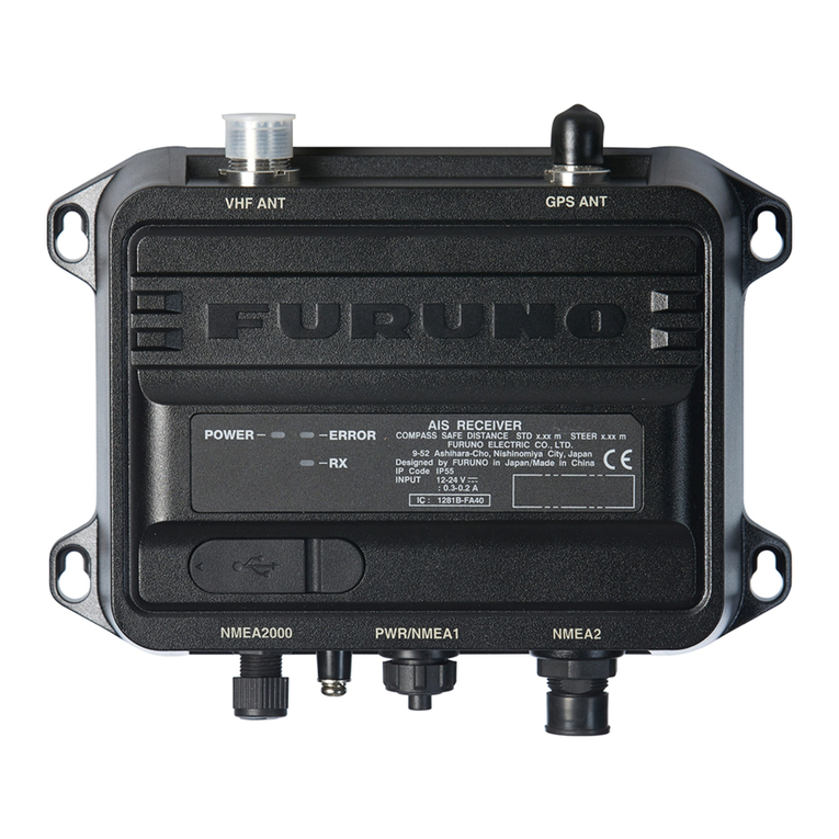
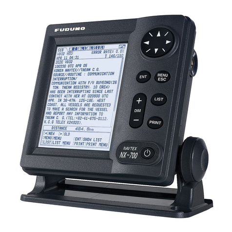
Furuno Navtex NX-700-B User manual

Furuno

Furuno Navtex NX-700-B User manual

Furuno FAX-410 Manual

Furuno

Furuno FAX-410 Manual

Furuno FA-30 User manual

Furuno

Furuno FA-30 User manual

Furuno FAX-214 User guide

Furuno

Furuno FAX-214 User guide

Furuno AA-45B User manual

Furuno

Furuno AA-45B User manual

Furuno RV-107 User manual

Furuno

Furuno RV-107 User manual
Furuno FA-40 User manual

Furuno

Furuno FA-40 User manual

Furuno DSC Receiver AA50 AA50R HF User manual

Furuno

Furuno DSC Receiver AA50 AA50R HF User manual

Furuno Weather Satellite Receiver SU18 Manual

Furuno

Furuno Weather Satellite Receiver SU18 Manual

Furuno Navtex NX-700-B User manual

Furuno

Furuno Navtex NX-700-B User manual

Furuno Navtex Receiver NX-500 User manual

Furuno

Furuno Navtex Receiver NX-500 User manual

Furuno RV-107 User manual

Furuno

Furuno RV-107 User manual

Furuno GV-86 User manual

Furuno

Furuno GV-86 User manual

Furuno RC-1800T User manual

Furuno

Furuno RC-1800T User manual

Furuno FAX-207 User manual

Furuno

Furuno FAX-207 User manual

Furuno MF/HF DSC/Watch Receiver DSC-60 User manual

Furuno

Furuno MF/HF DSC/Watch Receiver DSC-60 User manual

Furuno FA-30 User manual

Furuno

Furuno FA-30 User manual

Furuno BBWX1 Owner's manual

Furuno

Furuno BBWX1 Owner's manual

Furuno NX-300-D User manual

Furuno

Furuno NX-300-D User manual

Furuno MF/HF DSC/Watch Receiver DSC-60 User manual

Furuno

Furuno MF/HF DSC/Watch Receiver DSC-60 User manual

Furuno RC-1800T User manual

Furuno

Furuno RC-1800T User manual

Furuno BBWX2 User manual

Furuno

Furuno BBWX2 User manual
Furuno eRideOPUS 6 User manual

Furuno

Furuno eRideOPUS 6 User manual
Furuno MF/HF DSC/Watch Receiver DSC-60 User manual
Furuno

Furuno MF/HF DSC/Watch Receiver DSC-60 User manual
Popular Receiver manuals by other brands

Panasonic TU-PT600B operating instructions

Panasonic

Panasonic TU-PT600B operating instructions

unicore UM620N Reference design

unicore

unicore UM620N Reference design

ICStation GS1299 user manual

ICStation

ICStation GS1299 user manual

Wet Sounds a link plus owner's manual

Wet Sounds

Wet Sounds a link plus owner's manual

Linear MEGACODE MDR-U installation instructions

Linear

Linear MEGACODE MDR-U installation instructions

Dish Network Hopper with Sling Setup

Dish Network

Dish Network Hopper with Sling Setup

Denon AVR-E400 owner's manual

Denon

Denon AVR-E400 owner's manual

Stahl 8295 Series operating instructions

Stahl

Stahl 8295 Series operating instructions

Fortec Star 786NA quick start guide

Fortec Star

Fortec Star 786NA quick start guide

Pioneer VSX-416-K operating instructions

Pioneer

Pioneer VSX-416-K operating instructions

Honeywell Limitless WDRR Series Installation and technical manual

Honeywell

Honeywell Limitless WDRR Series Installation and technical manual

Silent Call Communications Sidekick II Signature Series manual

Silent Call Communications

Silent Call Communications Sidekick II Signature Series manual

NAD VISO FIVE Service manual

NAD

NAD VISO FIVE Service manual

Rockford Fosgate RFX9901DM2 instruction manual

Rockford Fosgate

Rockford Fosgate RFX9901DM2 instruction manual

Kramer TP-573 user manual

Kramer

Kramer TP-573 user manual

Yamaha RXV765 - RX AV Receiver owner's manual

Yamaha

Yamaha RXV765 - RX AV Receiver owner's manual

Onkyo TX-RZ900 Basic Manual

Onkyo

Onkyo TX-RZ900 Basic Manual

Marantz NR1604 owner's manual

Marantz

Marantz NR1604 owner's manual

manuals.online logo
manuals.online logoBrands
  • About & Mission
  • Contact us
  • Privacy Policy
  • Terms and Conditions

Copyright 2025 Manuals.Online. All Rights Reserved.