Gator Automatic Butt Fusion Range
Operating Manual
EDOI6922 Page 4 of 44 Issue 02
1 Safety instructions
These operating instructions must be followed to ensure safe operation of the
Gator automatic butt fusion machine and operators must be fully conversant with
the safety instructions.
Fusion Group Limited can offer basic training and regular maintenance where
required.
Only use undamaged equipment that has been properly maintained and
calibrated. Refer to section 5 maintenance and care of this operating manual for
further information.
1.1 Precautions when lifting
Where necessary, operators are advised to request for assistance when carrying,
moving or lifting this equipment.
1.2 Risk of fire or explosion
Do not use this equipment in combustible gaseous environments.
1.3 Risk of electrical shock
This equipment must be connected to a suitable electrical earth supply.
Depending upon the model, this equipment requires a power
supply of 100V, 110V or 220V AC. Avoid walking or standing on
cables and ensure that cables are safely routed.
For safety purposes, this machine has been fitted with overload
protection and a residual current device (RCBO).
Always take care where you see the electrical warning labels displayed. Only
authorised engineers must attempt to open electrical enclosures.
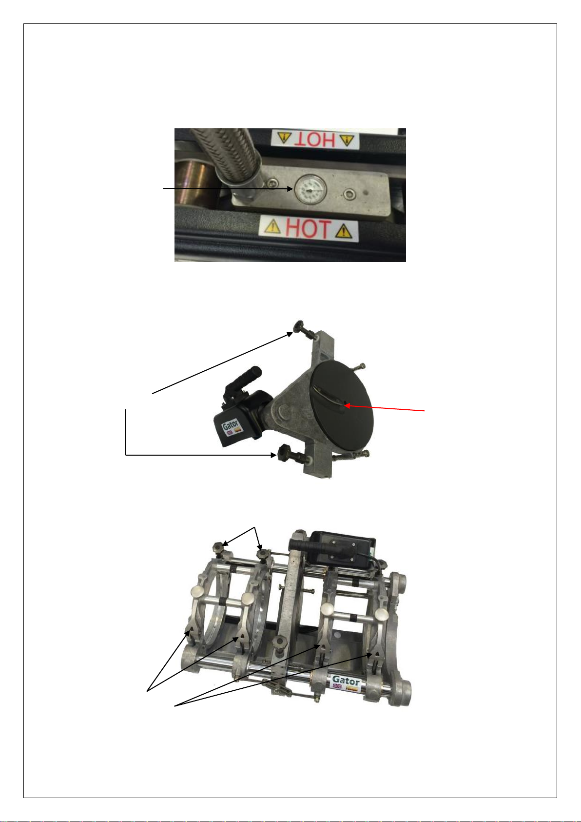
1.4 Risk of burning.
The process of Butt Fusion Welding uses a heater plate that typically runs at
temperatures in excess of 200ºC. The use of heat resistant gloves is strongly
recommended, as is use of suitable eye protection.
1.5 Precautions specific to Automatic Butt Fusion Machines
This unit is automated and as such, uses moving linkages during its operation that
will move without operator intervention. Care must be exercised during automated
trim, check and jointing cycles. An audible alarm will be heard, as a warning, prior
to and during automated movements.
It is the responsibility of the control unit operator to ensure that all personnel are
clear of the equipment before activating the control for the automated cycle.
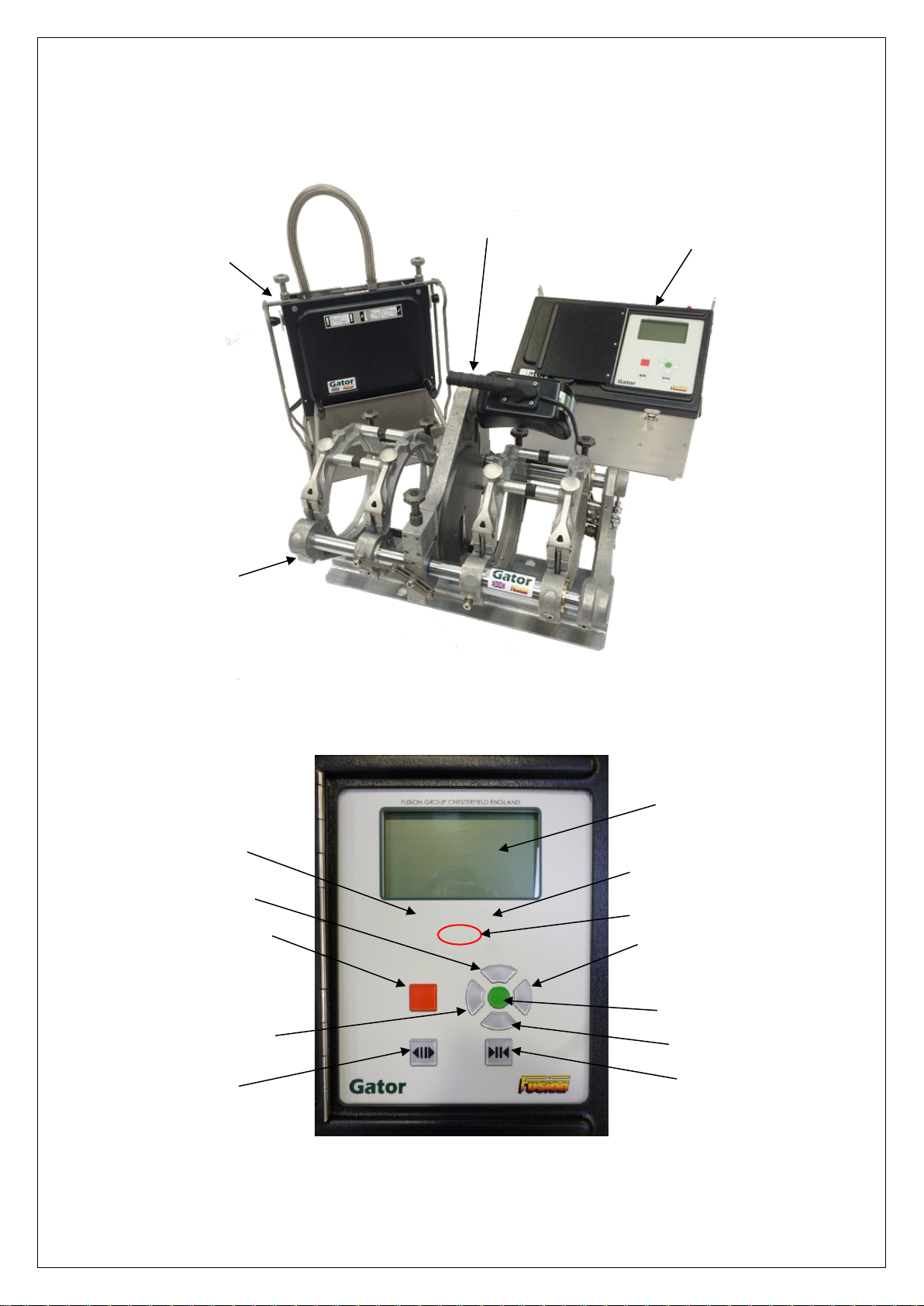
In the event of an emergency situation activate the emergency stop button that is
fitted to every machine and cuts all the power to the control system. The button
may be found at the top of the control box enclosure.
If necessary, the chassis clamps may be opened or closed using the silver
coloured open/close buttons.