Fuso Multi Use Tester III User manual

Multi Use Tester III
MUT-III Instruction Manual

MUT-III Instruction Manual
Preface
This instruction manual provides information about MUT-III functions, operating procedures and other
details.
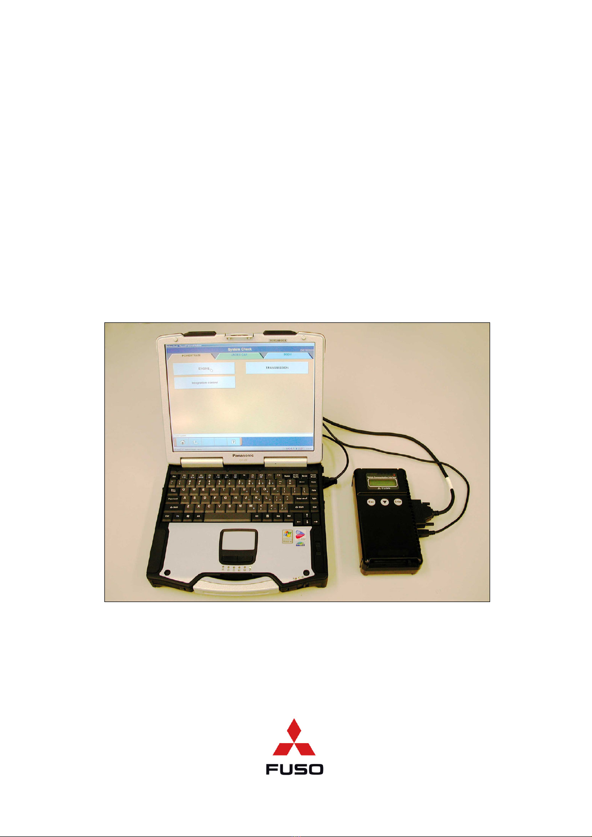
An understanding of the functions and operating procedures for both the MUT-III system and the
Vehicle Communication Interface (referred to as V.C.I. hereafter) will allow users to perform precise and
efficient fault diagnosis for vehicle-mounted Electronic Control Units (referred to as ECU hereafter) that
can be serviced with the MUT-III.
Please ensure that this instruction manual is read completely prior to using the MUT-III system, as the
operating procedures may vary, depending upon the particular type of vehicle electronic control unit.
Please note that the information described within this manual may not be fully consistent with certain
products, due to specification changes or version upgrades.
Table of Contents
Chapter 1 Product Overview........................................................................................ 1
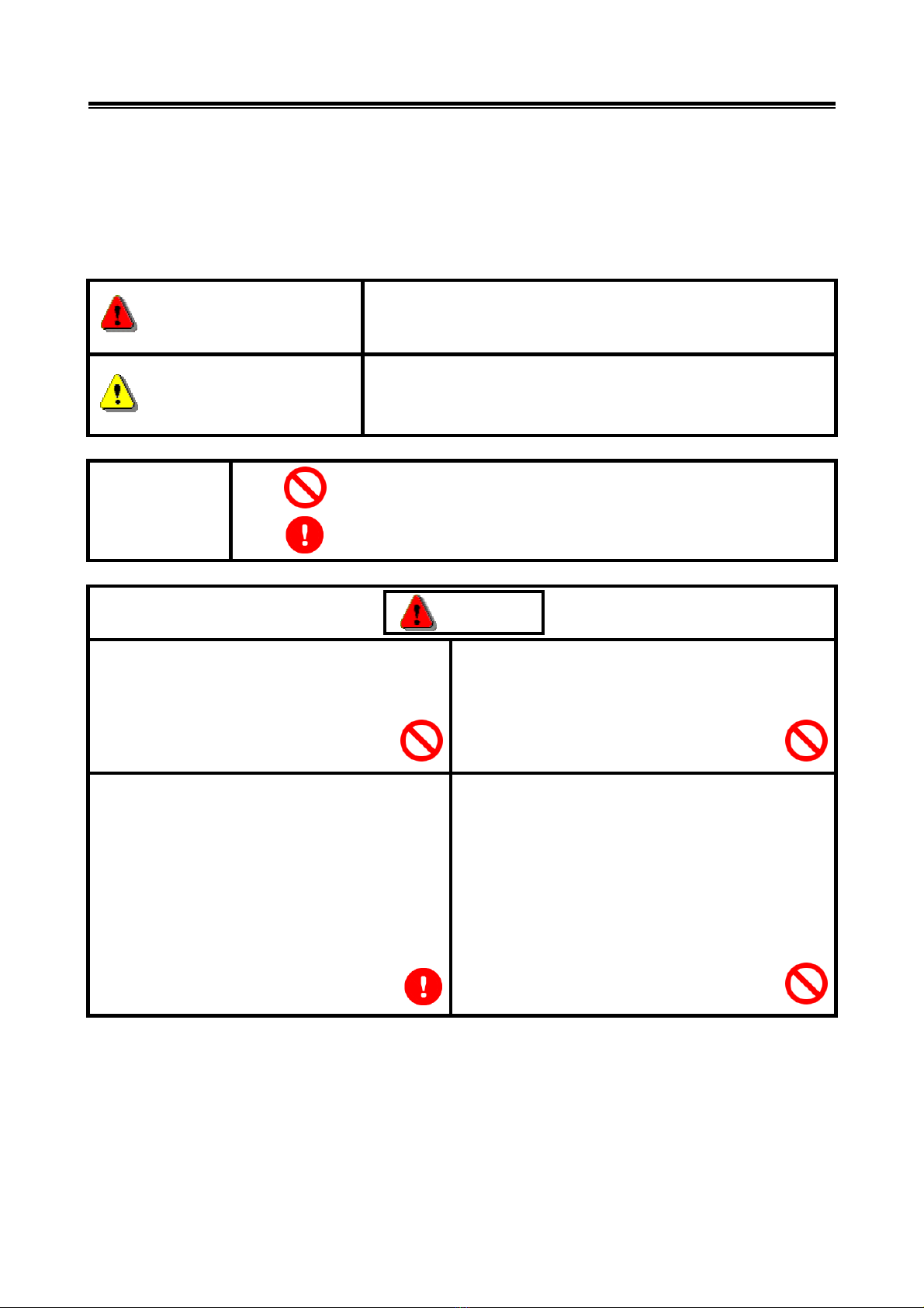
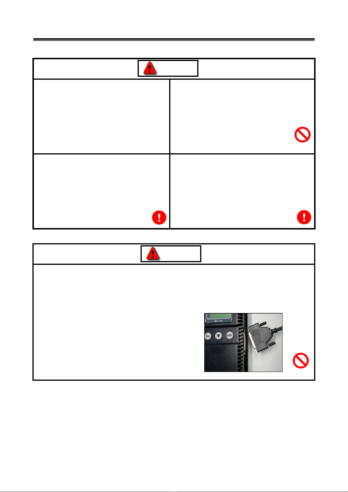
1-1. Precautions ...........................................................................................................................2
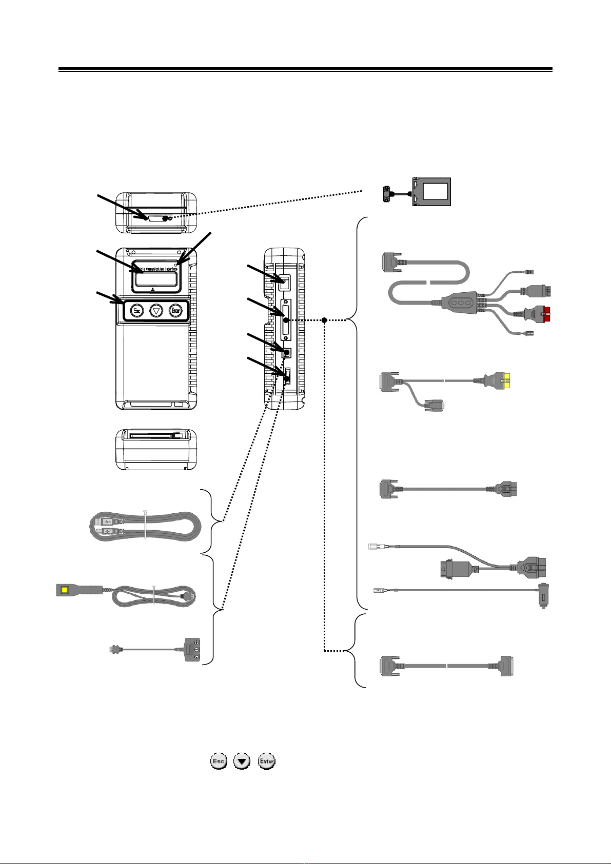
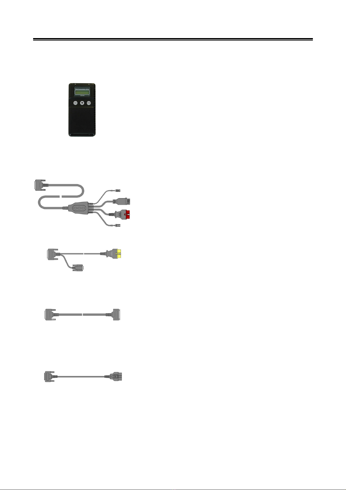
1-2. V.C.I. Exterior Diagram and Part Names...............................................................................3
1-3. Description and Usage of MUT-III Components....................................................................4
1-4. Harness Connection Procedures and Connection Order ......................................................6
1-5. Connection Harness and Vehicle Combinations ...................................................................7
Chapter 2 MUT-III Functions ........................................................................................ 8
2-1. Basic Functions.....................................................................................................................8
2-2. V.C.I. Function.......................................................................................................................8
Chapter 3 MUT-III Operating Procedures .................................................................. 10
3-1. Start-Up Procedures for PC and MUT-III System................................................................ 11
3-2. Description of Operating Screens .......................................................................................12
3-3. Description of Buttons on the Operating Screens ...............................................................13
3-4. Operating Procedures for the MUT-III System ....................................................................15
3-5. Shutdown Procedures for the PC and MUT-III System .......................................................17
3-6. Removing a memory card from PC ..................................................................................18
Chapter 4 Operating Procedures for Diagnostic Functions.................................... 19
4-1. Operating Procedures for Diagnostic Trouble Codes (DTCs) .............................................20
4-2. Operating Procedures for the Data List...............................................................................21
4-3. Operating Procedures for the Actuator Test ........................................................................31
Chapter 5 Operating Procedures for the Drive Recorder ........................................ 36
5-1. Recording with the Drive Recorder .....................................................................................37
5-2. Handling the Recorded Data...............................................................................................51
5-3. Analyzing Recorded Data....................................................................................................55

MUT-III Instruction Manual
Chapter 6 Operating Procedures for Measurement Functions............................... 62
6-1. Operating Procedures for Measurement Functions ............................................................63
Chapter 7 Other functions.......................................................................................... 64
7-1 Operating Procedures for V.C.I. Stand-alone Diagnosis ......................................................66
7-2 Operating Procedures for the Engine VIN Writing................................................................70
7-3 Operating Procedures for Immobilizer Registration .............................................................71
7-4 Operating Procedures for Pulse Converter ..........................................................................74
7-5 Operating Procedures for the OBD-II Test Mode menu........................................................76
7-6. Operating Procedures for Air Suspension Calibration.........................................................79
7-7 Operating Procedures for Language Switching....................................................................82
Chapter 8 Troubleshooting Measures....................................................................... 83
8-1. Troubleshooting Measures Classified by Symptom ............................................................83
Chapter 9 Reference................................................................................................... 84
9-1. V.C.I. Electrical Properties ..................................................................................................84
Appendix ..................................................................................................................... 85
<Glossary>.................................................................................................................................85

For Your Safety
For Your Safety
To ensure proper use of this product and prevent personal injury and property damage, various graphic
displays are used in the user’s manual. The graphic displays and respective meanings are described
below.
Warning
Warning messages alert you to a procedure or practice which,
if not followed correctly, could lead to death or serious injury.
Caution
Caution messages alert you to a procedure or practice which, if
not followed correctly, could lead to serious injury and/or
property damage.
Icon
Examples
The symbol alerts you to a prohibited action.
The symbol alerts you to an action that must be enforced.
Drivers should not operate the unit while
driving.
• Operating the unit while driving may result in
a traffic accident.
Do not plug in or unplug the power AC adapter with
wet hands.
• Doing so results in the risk of electric shock.
When using the cigarette lighter plug to supply
power to the V.C.I. unit, be sure the power
voltage supplied is DC32V or less.
• Applying a voltage greater than DC32V
results in the risk of fire.
• MUT-III as provided to dealers includes 12V
accessory / cigarette lighter plug adapter to
power MUT-III during extended test drives.
Maximum voltage the V.C.I. can withstand is 40V.
Do not use the V.C.I. on systems greater than the
32-volt system mentioned previously.
• Violating this requirement results in the risk of a
ground fault, damage and/or electric shock.
Warning

For Your Safety
The V.C.I. screen is liquid crystal display or
LCD. In the unlikely event that the display
breaks due to impact, do not let your skin come
in contact with the LCD fluid.
If your skin comes in contact with the LCD fluid,
wash your skin thoroughly with water. If skin
rash or abnormality occurs seek medical
attention from a doctor.
Do not use the unit if the power AC adapter plug or
cord is damaged or plugging into the outlet is
loose.
Use under such conditions may result in electric
shock, an electric short and/or fire.
Be sure to hold the harness connector when
disconnecting from the vehicle. Do not
disconnect the harness by pulling on the cord.
Pulling the cord rather than the connector may
result in damage to the lead wire inside the
cord, thereby causing a short and possibly
starting a fire.
Unplug the power AC adapter from the outlet when
the unit is not in use.
Failure to do so may result in injury, burns, electric
shock caused by insulation deterioration, or fire
due to a short circuit.
When the harness is connected to the V.C.I., be sure to check the top and bottom of the connector
and connect the harness perpendicularly to the connector of the V.C.I.
Connecting at an angle may result in bending of the pins of the connector.
Check for the secure connection of the harness before tightening of the screw locks.
The bent pin may contact the connector case, thereby causing an electric short which leads to
damage to the V.C.I.
Warning
Warning

For Your Safety
Please Note
Do not expose the PC or V.C.I. to direct sunlight or high temperatures, or leave the unit in sun-heated
cars. Such action may result in system failure.
Store the PC and V.C.I. in a dry environment at room temperatures.
Moving the PC and V.C.I. to a location with a very different temperature and humidity than that of the
previous location may result in external or internal condensation. Caution is required.
Protect the PC and V.C.I. from exposure to elements such as rain, dirt, dust, food and liquids.
Be careful when handling the PC and V.C.I. Dropping the units may result in damage.
Do not expose either unit to engine oil, gasoline, antifreeze or battery acid. Also, do not clean the PC
or V.C.I. case using solutions such as thinner or benzene. Doing so may result in deterioration of the
case surface.
Prior to connecting the MUT-III main harness between the V.C.I. and vehicle, turn the IG switch to
OFF.
Connecting the V.C.I. harness with the IG switch ON may damage the V.C.I. programming.
Use only the power AC adapter included with the PC (or approved replacement), power cigarette
plug, other probes, main harness and other cables.
Use of unspecified parts may result in damage or malfunction due to excess voltage or insufficient
contact.
The LCD display of this unit turns off when the supplied voltage is less the DC 8V. This is not an error.
The power supplied should be from 8VDC to 32VDC.
Keep all V.C.I. connectors and openings away from dirt and static electricity. Exposure to dirt and
static electricity may result in malfunction and damage.

Product Overview
1
Chapter 1 Product Overview
1-1. Precautions............................................................................................................................P.2
1-2. V.C.I. Exterior Diagram and Part Names ...............................................................................P.3
1-3. Description and Usage of MUT-III Components ....................................................................P.4
1-4. Harness Connection Procedures and Connection Order ......................................................P.6
1-5. Connection Harness and Vehicle Combinations .......................................................................P.7

Precautions
2
1-1. Precautions
Service Work Precautions
• Be sure to follow all basic service work precautions when using MUT-III during vehicle inspection
and service work.
• For detailed information regarding service work precautions, refer to the service instruction manual
of each vehicle.
Work Precautions
• When performing vehicle inspection work at the work site with the engine running, either use an
exhaust gas discharger or ventilate the area sufficiently.
• When working on a vehicle, be sure to apply the parking brake and set wheel chocks in place to
prevent the car from moving.
Driving Precautions
• If you wish to use MUT-III while driving the target vehicle, first verify that all parts are properly
assembled.
• While driving, always have an assistant operate MUT-III.
• Be sure that the MUT-III maintenance harness and other cables will not interfere with driving.
• Install and remove the PC and V.C.I. with the vehicle parked, IG switch OFF.
PC Usage Limitations
Do Not Install Software on the PC
• The MUT-III PC is a special service tool. Do not install any software other than MUT-III software
provided by MMNA onto the unit. Installation of other software results in the risk of MUT-III system
failure.
• Any unauthorized software will not be supported. Technical support for units with unauthorized
software will be charged additional technical support fees to return the unit to its authorized state of
operation.
• All unauthorized software will be erased with each new upgrade.

V.C.I. Exterior Diagram and Part Names
3
1-2. V.C.I. Exterior Diagram and Part Names
Part names for the main unit are shown in the figure below.
I/F Cartridge
Harness, MUT-III TYPE-B
(MH062962)
Harness, MUT-III TYPE-C
(MH062930)
Harness, MUT-III TYPE-E
(MH063661)
(MH063662) Only for Europe.
Sub harness for drive recorder
(MH063663)
Harness, MUT-III TYPE-D
(MH062951)
< Part Names >
1. I/F Cartridge Port 5. Power Switch
2. LCD Display Screen 6. Harness Port
3. Indicator Lamp 7. USB Port
4. Control Buttons< , , >
(Used for V.C.I. stand-alone functions)
8. Trigger Port
Measuring Adapter (MH063670)
Trigger Harness (MH063669)
USB Cable (MH063668)
1
2
4
5
6
7
3
FUSO
8

Description and Usage of MUT-III Components
4
1-3. Description and Usage of MUT-III Components
(1) V.C.I. (MH062927)
Communications interface used for connecting the vehicle
ECU to a PC
1. When Connected to PC
• Provides ECU fault diagnosis (interactive fault
diagnosis)
2. V.C.I. Stand-Alone Usage (usage while disconnected
from PC)
• Drive recorder
The V.C.I. can be utilized, without modification, for both
12V / 24V vehicles.
(2) Harness, MUT-III TYPE-B (MH062962)
This harness is used to connect the V.C.I. to a vehicle.
Power can be supplied to the V.C.I. via the cigarette lighter
plug, depending upon the particular model of vehicle.
Refer to section 1-5 for connection of harness and vehicle
combinations.
(3) Harness, MUT-III TYPE-C (MH062930)
This harness is used for checking or data recording of the
Air Suspension ECU, manufactured by WABCO.
This harness is used with Air Suspension I/F Cartridge.
(4) Harness, MUT-III TYPE-D (MH062951)
This harness is used as an extension for TYPE-B/TYPE-E
harnesses.
(5) Harness, MUT-III TYPE-E
(MH063661)
(MH063662) Only for Europe.
This harness is used to connect the V.C.I. to a vehicle.
Refer to section 1-5 for connection of harness and vehicle
combinations.
Please refer to the service guide for each vehicle.

Description and Usage of MUT-III Components
5
(6) Sub harness for drive recorder (MH063663)
This Sub harness is used with the Harness, MUT-III
TYPE-E (MH063661,MH063662) used for drive recorder
function.
(7) USB Cable (MH063668)
This harness is used to connect the V.C.I. to a PC.
(8) Trigger Harness (MH063669)
The button on this harness is used to generate manual
triggering for data acquisition during data recording, while
using the drive recorder function.
(9) Measurement Adapter (MH063670)
This adapter is used to connect the V.C.I. to the measuring
probes.
(10) Measuring Probes(MH063671)
The measuring probes are used with the voltmeter and
ohmmeter.
Either MUT-II accessory probes (MB991499) or
off-the-shelf probes can be utilized.
(11) I/F Cartridge
The I/F Cartridge is used to perform special functions that
cannot be performed by the V.C.I. alone.
The following I/F Cartridges, which are from the MUT-II,
can be utilized:
• Electronic Governor I/F Cartridge
• Air Suspension I/F Cartridge

Harness Connection Procedures and Connection Order
6
To perform diagnostics, first connect the cabling by following the procedures described below.
[1] Restart the PC.
[2] Connect one end of the USB cable to the V.C.I.
[3] Connect the other end of the USB cable to the PC.
[4] Connect the MUT-IIIharness to the V.C.I.
[5] Connect the MUT-IIIharness to the vehicle’s diagnostic connector.
* To disconnect the cabling, reverse the above procedures:
[6] Turn the V.C.I. power switch ON and check to ensure that the indicator lamp, located in the
upper right corner of the LCD screen, illuminates in green.
[7] Start up the MUT-III system software on the PC and turn the vehicle ignition switch ON to
begin performing diagnostics.
* If the version of the V.C.I. software installed in the PC is different from the version of the
firmware within the V.C.I. itself, then a V.C.I. software version upgrade will be initiated. If a
version upgrade error occurs, restart the V.C.I. while simultaneously depressing the
button on the V.C.I., in order to resume diagnostic testing.
1-4. Harness Connection Procedures and Connection Order
Open the lid covering the USB port,
which is located on the Right side of the
PC and indicated by the symbol.
Plug the USB connector into the port.
<Connecting the USB Cable to the PC>
[5][2]
[3] [4]
[6] [7]
[1]
<Connecting the Measuring Adapter and Probes>
Connect the Measuring Adapter to the V.C.I. trigge
r
port then connect the measuring probes to the
adapter, matching the color of each probe plug to
the appropriate color on the adapter jack.
Connect the trigger harness to the
trigger port of the V.C.I.
<Connecting the Trigger Harness>

Connection Harness and Vehicle Combinations
7
1-5. Connection Harness and Vehicle Combinations
• Connect either a "TYPE-B" or “TYPE-C” or "TYPE-E " harness to the vehicle’s 16-pole / 12-pole
connector and perform fault diagnosis.
• A "TYPE-D" harness can be utilized as an extension for "TYPE-B / TYPE-E" harnesses.
• Use a combination of harnesses, either a "TYPE-B" or “TYPE-C” or "TYPE-E " (O), and either a
"TYPE-D" or “Drive recorder" (●), depending upon the performing operation.
*1 : Thailand, Chile
Harness Name Appearance
01 TYPE-B
MH062962
02 TYPE-C
MH062930
03 TYPE-E
MH063661
MH063662(Only for Europe.)
04 TYPE-D
MH062951
05 Drive recorder
MH063663
01 02 03 04 05
HarnessName
Vehicle
TYPE-B TYPE-C TYPE-E TYPE-D Drive
recorder
~EURO3, ~EPA04, ~Taiwan 3rd terms
O ●
EURO4~, EPA07~, Taiwan 4th terms~,
EURO3(Limited country*1)~ O ●●
Equipped with Air Suspension
manufactured by WABCO O

Basic Functions / V.C.I. Function
8
Chapter 2 MUT-III Functions
2-1. Basic Functions
• The MUT-III can be utilized for all types of vehicle electronic control units (incorporating the
diagnostics function).
• The MUT-III reads each diagnostic code and displays it as a name.
• Using serial communications, the MUT-III reads the RAM data (data list) within the ECU that is
required for servicing, thus enabling the display of both graphs and numeric values converted to
physical quantities. (Only for ECUs that support serial communications.)
• The MUT-III can forcibly drive or forcibly stop the actuators required for servicing. (Only for
ECUs that support serial communications.)
• Using its voltage measuring function, the MUT-III can measure DC voltage ranging from +/-40V.
• Using its resistance measuring function, the MUT-III can measure resistance ranging from 0 ~
100kOhm.
2-2. V.C.I. Function
<Using the V.C.I. with a PC>
2-2-1. Fault Diagnosis
The V.C.I. can perform fault diagnosis by receiving
commands from a PC and communicating with a vehicle
ECU.
*The buttons on the V.C.I. will not function while it is
connected to a PC.
[Start-up Screen]
• The screen to the left will be displayed when the USB
cable is connected to the main unit.
The direction of signal flow between the PC and the V.C.I.
will be indicated by an arrow, such as [P->V] or [P<-V].

Basic Functions / V.C.I. Function
9
<Using the Stand-Alone V.C.I.>
2-2-2. Measurement Functions: Voltmeter / Ohmmeter
The V.C.I. can read voltage / resistance values that are
applied to its trigger port, displaying these numeric values
on its LCD screen.
(1) Connect the Measuring Adapter to the V.C.I. trigger port
then connect the measuring probes (MB991499, etc.) to
the adapter, matching the color of each probe plug to the
appropriate color on the adapter jack.
(2) Connect the vehicle to the V.C.I. using the appropriate
harness, then turn the V.C.I. power switches ON.
(3) Press the button to select either the Voltmeter or the
Ohmmeter from the main menu (refer to the photo at left)
then press the button to perform the measurement.
<For Your Reference>
• DC voltages ranging from +/-40V can be measured.
• Resistance values ranging from 0 ~ 100kOhm can be
measured.

MUT-III Operating Procedures
10
Chapter 3 MUT-III Operating Procedures
3-1. Start-Up Procedures for PC and MUT-III System...................................................................P.11
3-2. Description of Operating Screens ..........................................................................................P.12
3-3. Description of Buttons on the Operating Screens..................................................................P.13
3-4. Operating Procedures for the MUT-III System
3-4-1. Selecting Desired Functions.......................................................................................P.15
3-4-2. Help Screen Functions ...............................................................................................P.16
3-4-3. Displaying the Instruction Manual...............................................................................P.16
3-5. Shutdown Procedures for the PC and MUT-III System
3-5-1. Shutdown Procedures for the MUT-III System ...........................................................P.17
3-5-2. Shutdown Procedures for the PC...............................................................................P.17
3-6. Removing a memory card from PC
3-6-1. Removal Procedures for a memory card from PC......................................................P.18

Start-Up Procedures for PC and MUT-III System
11
3-1. Start-Up Procedures for PC and MUT-III System
[PC Start-Up]
Power up the PC.
Wait for the Windows operating system to
start up.
For more detailed PC operating instructions,
please refer to the instruction manual
included with the PC.
[Entering User Name / Password]
Once Windows is running, the logon
dialogue will be displayed.
Enter both the user name and the password
to logon as an administrator, then select the
"OK" button.
[MUT-III Start-Up]
Once the desktop screen is displayed,
touch the "FUSO MUT-III" icon, which is
located on the desktop, twice quickly.
This action will start MUT-III.
Information about Trademarks
• Microsoft®, WindowsXP®and Internet Explorer®are trademarks and registered trademarks of
Microsoft Corporation in the USA and other countries.
• Acrobat Reader Copyright 1987-2001 Adobe Systems Incorporated. All rights reserved.
Adobe, Adobe logo, Adobe Acrobat and Adobe Acrobat logo are trademarks of Adobe Systems
Incorporated.
[Enlarged View
of Icon]

Description of Operating Screens
12
3-2. Description of Operating Screens
<Start-Up Screen>
<System Selection Screen>
<Diagnostic Screen>
This button is used to activate the Fault
Diagnostics System. Refer to section
3-4 for operating procedures.
This button is used to shut down the
MUT-III System.
Refer to section 3-5 for operating
procedures.
This button is used to view the MUT-III
Instruction Manual on the PC.
Refer to section 3-4-3 for operating
procedures.
On the system selection screen,
different main item categories can be
viewed by selecting the different tabs,
located at the top of the screen.
Service Guide Display
A
dditional functions will be included
later.
This screen displays titles for 3
hierarchies, in order to allow the user to
understand which operation is currently
running in each system.
Selecting a different tab from the upper
part of the screen will not change the
title displayed.

Description of Buttons on the Operating Screens
13
3-3. Description of Buttons on the Operating Screens
The names and functions for the button icons are as follows:
English Except
English
Main menu Returns the screen to the main menu.
Return Home Returns the screen to the start screen.
Return one level Returns the screen to the upper layer screen.
Print screen Print the screen image.
Help Displays online help.
OK or YES Determines an outcome.
Cancel Cancels the operation or closes the screen.
Select drive Select drive
Select folder Select folder
View vehicle information Displays vehicle information.
Button Image
Button Name Button Function
Select item Select an item.
Item group registration Item group is registered.
Item group clearance Registered item group is cleared.
Item sort Sorts a chosen item.
View text Displays text.
View graph1 Displays four items on four graphs.
View graph2 Displays (overwrites) four items on one graph.
Change time scale Changes the graph display time scale.
Change data scale Changes the graph display time scale.
File save Sets extraction conditions and saves the extracted data
in a file.
Save to HDD Save to Hard drive.
Delete file Deletes files.
Alphanumeric input screen Opens the alphanumeric input screen.
Print of the data Print of the data.
Displays troubleshooting Displays a troubleshooting

Description of Buttons on the Operating Screens
14
English Except
English
1/3 Change of function button
(1/3 display)
View V.C.I.
Regeneration data
Displays a list of V.C.I.
Regeneration data.
Button Name Button Function
Button Image
Data transfer Transmits the data of the selected block to the PC.
Open setting screen (PC) Opens the setting screen used to record information
on the PC.
Open setting screen (V.C.I.) Opens the setting screen used to record information
on the V.C.I..
Manual trigger Generates a manual trigger.
Trigger point data Jumps to the trigger point.
Data Retrieval Opens the search condition settings screen.
Data extraction settings Opens the extraction condition (data) screen.
Time setting Opens the extraction condition (time) screen.
Add Adds items.
Correlation chart Opens the correlation chart settings screen.
Distribution map Opens the distribution chart settings screen.
Pause Pause
Record finish Record finish
Trigger setting Trigger setting
Systems select Systems select.
Exhaust Exhaust
Air intake Air intake
4 button Shows an enlarged view of the
4 buttons.
Front/Rear change Front/Rear change
Esc ESC Key function of V.C.I.
Enter Enter Key function of V.C.I.
Down arrow Down arrow Key function of V.C.I.
Zero point calibration Corrects the measurement function.
This manual suits for next models
1
Table of contents