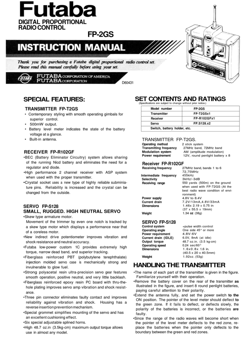
•Referto Fig.2 for the operation of each channel andthe name of
each part.
•When the power switch is set to ON, the pointer of thelevelmeter
willdeflect.Since thisindicates the antenna output, itshould deflect
to graduation 7. Since thisindication is differentwhen the antenna
is contracted and when itisextended fully,check theindication
when the antenna isextended fully.(The indication willalsobe dif-
ferentwhen theantenna is held inyour hand and when free)
•Next,
push the batterycheck switch. The
level
meter
will
indicate
the batteryvoltageat thistime.
The battery is OK ifthe meter pointer deflects to the green zone.
Charge thebatterywhen thepointer deflectsto the boundary be-
tween the green and red zones.
•Using dual travel
When the dual travelswitch is set to ON, the steering angle can be
madesmall withintherange of thehatched linesofFig.3. The steer-
ingangle isvariablewithinthe range maximum, 90%of totaloper-
ating angle, minimum 40%.
•The dual travelaileron switch should normally beset to OFFSetthis
switch toON when desiringto make theaileronsteeringangle small such
asslowroll,etcThen set thesteeringangle withthetrimmer
*The dual travelelevatorswitchshould normally be set toOFFBut when
desiringa large steeringangle such as spins,etc, set theswitchtoON and
adjust the steeringangle withthe horn adjuster trimmerforlevelflight.
Kick-up willoccurand theelevatorsteeringangle willbecome large when
the switchis OFF
•The
receiver
channel order
is
shown
in
Fig-.5.
Since each lead wireof the connectors is color coded, connect the
servos inaccordancewiththesecolors. Attachingtheaccessorychan-
neltabs is convenient.
Fig.
3
