manuals.online logo
Brands
  1. Home
  2. •
  3. Brands
  4. •
  5. FUTABA
  6. •
  7. Remote Control
  8. •
  9. FUTABA T7PXR Technical manual

FUTABA T7PXR Technical manual

1M23Z05402
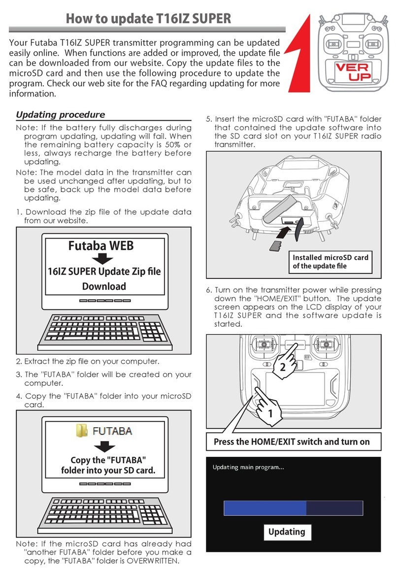
T7PXR/T7XC Software Update Method
Whenever improvements and new functions are available, the software of your T7PXR/T7PX/T7XC
radio transmitter can be updated easily online free of charge. The updated software file will be
shown on our website. You can download it and make a copy on your microSD card. Below is the
procedure for the software update.
Procedure for the software update
Caution: Before you update the software, the battery that is connected to the T7PXR/T7PX/T7XC
should be fully charged.
Note: During the software update, the model data that is stored in the T7PXR/T7PX/T7XC
should be kept without any change. (NOT erased and NOT changed.) However, for your safety,
making a backup of your model data before the software update is highly recommended.
1. Download the zip file of the update data
from our website.
2. Extract the zip file on your computer.
3. The "FUTABA" folder will be created on your
computer.
4. Copy the "FUTABA" folder onto your
microSD card.
Note:
If the microSD card has already
had "another FUTABA" folder before you
make a copy, the "FUTABA" folder is
OVERWRITTEN.
5. Insert the microSD card with "FUTABA"
folder that contained the update software
into the SD card slot on your T7PXR/T7PX/
T7XC radio transmitter.
6. Turn on the transmitter power while pressing
down the "HOME" button. The update
screen appears on the LCD display of
your T7PXR/T7PX/T7XC and the software
update is started.
7. When the software update is completed,
"Completed" message is shown on the LCD
display of your T7PXR/T7PX/T7XC. (See
attached picture.)
8. Turn off the power switch of your T7PXR/
T7PX/T7XC and remove the microSD card
from the card slot.
Possible Problems
When one of the error messages shown
below appears on the LCD screen of your
T7PXR/T7PX/T7XC, the software update will
not be completed.
"Low battery."
Software update is postponed because of low
battery. Retry the software update after the
battery is recharged.
"Update file not found."
The T7PXR/T7PX/T7XC cannot find the up-
date file on the microSD card. Check to be
sure all the update files have been copied
onto the microSD card.
"Broken file."
The T7PXR/T7PX/T7XC detects the update
file error. The update file may be broken or for
another transmitter.
"Write error."
The software update procedure is stopped for
an unknown reason. Contact your local ser-
vice center when this error message appears
on the LCD screen of your T7PXR/T7PX/
T7XC.
HOME button
The Gyro Link is a function that allows you to set the parameters of the car gyro wirelessly from the
transmitter.
*A gyro compatible with the wireless setting:GYD550 (As of April 2020)
 8SWR¿YHSUHVHWVFDQEHVZLWFKHGZKLOHGULYLQJ*\URGDWDVZLWFKLQJIXQFWLRQ
 7KH6%86VHUYRGDWDFDQEHVHWZLUHOHVVO\IURPWKHWUDQVPLWWHUYLDWKHJ\UR
$UHFHLYHUFRPSDWLEOHZLWKWKHZLUHOHVVVHWWLQJIXQFWLRQLVUHTXLUHG$VRI$SULO56%656%6(LVFRPSDWLEOHZLWK
ZLUHOHVVVHWWLQJ3OHDVHXSGDWHWKHSUHYLRXVUHFHLYHUWRYHUVLRQRUODWHU
:KLOHXVLQJ*\UR/LQNZLUHOHVV6%86VHUYRDGMXVWPHQWZLOOQRWIXQFWLRQ
 7REHDEOHWRFRQWUROJ\URJDLQHWFIURPWKHWUDQVPLWWHULWLVQHFHVVDU\WRHQDEOHWKHJ\URPL[LQJIXQF
tion of the transmitter.
(Preparation)
- Connect the receiver and gyro according to the connection diagram below.
* The connection diagram is a reference diagram for selecting the gyro link connection method. Please read the gyro instructions for details
or cautions.
- Turn on the power switch PWR of the transmitter to display the Gyro Link screen.
* Note that this cannot be used with the display switch DSP.
- Turn on the receiver power switch.
1(Gyro read)
When you open the Gyro Link screen from the Accessory menu or Custom menu, the connection method selec-
tion screen is displayed. Tap the button according to the connection method between the gyro and the receiver.
The Gyro type and currently set contents are read.
Using the Gyro Link function
Additional function / Wireless Gyro setting (Gyro Link)
V7.0
If "Failed" is displayed on the screen, communication
with the gyro has not been performed normally.
Check receiver, gyro and battery connections,
transmitter and receiver power switches, and repeat
reading.
Home screen Menu screen
Accessory menu screen Gyro Link
Menu-2
Menu-1
When not using S.BUS connection,
select [Wireless 1 (receiver Ch1)]
* When the S.BUS connection is
not used, the gyro data switching
function cannot be used, so only
[Gyro data 1] is displayed.
When using S.BUS connection,
select [Wireless (receiver S.BUS2)]
GYD550
Connect the power supply
of the receiver to the B/C
connector or each of CH1
to CH4.
Receiver
Gyro gain CH3
Gyro
Steering servo
Steering CH1
GYD550
Connect the power supply
of the receiver to the S.
BUS2 connector or each of
CH1 to CH4.
Gyro
Steering servo
S.BUS Receiver
S.BUS/S.BUS2 port
*Do not use the Gn
2(Writing to Gyro)
Execute this function to write the setting data to the Gyro.
Tap the setting item [Write] on both the Basic setting screen and the
Gyro data screen.
After "Read Please wait" is displayed, an electronic
sounds and writing ends. Be sure to write after changing the settings.
- If "Failed" is displayed on the screen, communication with the gyro has not been
performed normally. Check receiver, gyro and battery connections, transmitter and
receiver power switches, and repeat [Write].
- Refer to "Setting method of each item" for the contents of the setting data.
4(Initialization)
Write the factory set Gyro setting data to the connected the Gyro. Tap [Reset] on the
gyro reading screen; the confirmation screen will be displayed. To execute, tap [Yes]
to hear an electronic sound and finish setting. To cancel, select [No] and tap it.
- If "Failed" is displayed on the screen, communication with the gyro has not been performed normally.
Check receiver, gyro and battery connections, transmitter and receiver power switches, and repeat [Reset].
Gyro reading screen
Basic setting screen
Example:
Basic setting screen
The gyro setting data is divided
into the Basic setting and Gyro
data (1 to 5) screens and dis-
played by the method shown on
the right.
- When the S.BUS connection is not
used, the gyro data switching function
cannot be used, so only [Gyro data 1] is
displayed.
Tap the [Value], the setting value will be displayed in blue, and [-] and [+] will be displayed at the bottom of the
screen. Touch [+] and [-] to set the data. In the case of selection type, touch the item to switch the data.
Display data list
Data settings
Basic setting screen Gyro reading screen
Gyro data screen
1/2 2/2
Basic setting
*In the T-FHSS SR mode, the servo position will not adjust until [Write], even if the "Limit" and "Neutral offset" functions are adjusted with [+] and [-].
Response mode
Gyro sensor response setting.
* Low Middle High speeds up response.
* In high mode, using the dead band angle is too small, the servo will
work continuously, but there is no problem in running. However, if strong
the servo will work continuously occurs, set to middle or low mode.
Limit
Adjustment function of maximum steering
angle.
* Operate the steering and adjust the left and right
separately so that the maximum steering angle is
obtained as long as the tires do not interfere with
the arms.
* If the adjustment value of the limit is small (the max-
imum steering angle is not adjusted), it becomes
easier to spin.
* During limit adjustment, the steering angle is am-
plified by 1.5 times, but this is not a malfunction.
However, perform drive after completing the limit
adjustment. Gain mode
Gyro internal control gain switching.
*
High gain is 1.5 times more sensitive than standard gain.
*
Normally set to standard.
Set to high gain if increasing the sensitivity setting of
the transmitter to the maximum value is not enough.
Neutral offset
Neutral adjustment function of the steering
servo.
* Do not use transmitter trim and sub trim. Make the
neutral setting with a gyro.
Reverse
Gyro control direction setting.
* If the car is turned to the left by hand steering
goes out on the right.
SR mode setting
Set to SR mode.
* Set the SR compatible servo to SR only when using
SR mode.
Gyro data 1/2 2/2
The gyro data setting screen has two pages, and the page can be a switch with the page switching button on the
upper right. Also, data can be set independently in each gyro operation mode (normal / AVCS).
AVCS and normal mode change button
The AVCS / NORMAL modes setting.
The gyro has 2 operating modes: NORMAL mode and AVCS mode.
In the AVCS mode, gyro control is firmer.
* The feel of operation is different, choose your favorite mode.
* NORMAL: The driver needs to perform counter-steer Operation opposite to the turn direction.
* AVCS: The gyro performs countersteer Steer in the turn direction.
Damper
Hunting suppression
The higher the value, the stronger the hunting
suppression. However, it will feel like the servo
response has worsened.
Damper point
Adjust the servo response due to the ef-
fect of the damper against the gyro effect.
* The smaller the value, the stronger the influence
of the Damper and the slower the servo speed.
* The higher the value, the slower the Damper will
operate and the better the response, but the more
likely it is that hunting will occur.
Tail slide speed
Adjust the speed of the tail slide (shake
the tail) when driving.
* Decreasing the numerical value decreases
the speed of the tail slide, and increasing the
numerical value increases the speed.
* Effective for adjusting the tail slide amount during
steering operation.
Steering control gain
Adjustment of intervention ratio of steer-
ing operation to gyro control.
When the numerical value is increased, the
steering operation of the driver is largely reflected.
* The steering response feels fast.
Steering speed
The function to adjust servo speed for steering operation
(same the function as servo speed of the transmitter).
* The smaller the value, the slower the servo speed.
Steering gain curve
Eight points of gain can be set up to the
endpoint based on neutral.
* It is set in conjunction with left-right symmetry.
* The vertical cursor line moves in
conjunction with the operation of the
steering.
Gyro data screen
1/2
Gyro data screen
2/2
Additional function / Gyro data switching function
*\URGDWDFDQEHVZLWFKHGZLWKWKHSXVKVZLWFKRUWULPOHYHUGLDORIWKHWUDQVPLWWHU8SWRJ\URGDWD
$OVRLWLVSRVVLEOHWRFKDQJHJ\URGDWDDFFRUGLQJWRWKHFRQGLWLRQRIWKHWUDQVPLWWHU8SWRJ\URGDWD
- Connect the gyro to the S.BUS2 terminal of the receiver.
- The gyro mixing function must be enabled.
1
On the Gyro mixing 1/2 screen, set the func-
tion to ON.
2On the Switch select screen, select the switch
you want to use for data switching.
3On the function selection screen, assign the
gyro data to be used from [Gyro data 1] to
[Gyro data 5].
When switching with the push switch
Gyro mixing screen 1/2 Switch select screen
Additional / Gyro mixing status on the home screen
Additional / Acuvance Xarvis / XarvisXX compatible (MC (ESC) -Link)
$GGHGDQLQGLFDWHWKHJ\URPL[LQJVWDWXVRQWKHKRPHVFUHHQ
'LVSOD\V WKH FXUUHQW RSHUDWLRQ PRGH 1RUPDO$9&6 DQG WKH
VHOHFWHGJ\URGDWD
7KH0&(6&/LQNIXQFWLRQLVQRZFRPSDWLEOHZLWK$FXYDQFH(6&;DUYLV;DUYLV;;
* Please contact Acuvance for details of Xarvis / XarvisXX functions.
Gyro mixing screen 1/2
Trim/Dial select select screen
Gyro mixing screen 2/2
1
On the Gyro mixing 1/2 screen, set the func-
tion to ON.
2On the Trim/Dial select screen, select the
switch you want to use for data switching.
3On the function selection screen, assign the
[Gyro data].
1
On the Gyro mixing 1/2 screen, set the func-
tion to ON.
2Display 2/2 of the gyro mixing screen. A list of
conditions and gyro data is displayed. Tap the
condition to be set.
3Select the gyro data to be assigned to the
condition.
When switching with the push switch
Gyro mixing status indicator
Home screen Menu screen
Accessory menu screen
Menu-2
MC(ESC)-Link
Menu-1
Select [MC970CR / Xarvis] when
using Futaba MC970CR or Acu-
vance Xarvis, and select [XarvisXX]
when using Acuvance XarvisXX.
* For Futaba ESC MC960CR, MC950CR, MC851C, MC602C, MC402CR, etc., please choose Other.
* MC970CR is available only in the Japanese market. (As of April 2020)
The throttle rate functions set on the "'5$7/
"screen.
:LWKWKHWKURWWOHUDWHIXQFWLRQ\RXFDQDGMXVWWKHDPRXQWRIWKURWWOHPRYHPHQWVRWKDWLWGRHVQRWUHDFK
IXOOSRZHUHYHQZKHQWKHWKURWWOHWULJJHUSXOOVWRWKHKLJKVLGH
%\DVVLJQLQJWKHWKURWWOHUDWHIXQFWLRQWRWKHVZLWFKZLWKWKH VZLWFK VHOHFW IXQFWLRQ WKH WDVN FDQ EH
VZLWFKHGRQR൵ZLWKWKHVZLWFKDQGWKHWKURWWOHRSHUDWLRQDPRXQWFDQFKDQJHWRIXOOWKURWWOHDFFRUGLQJ
to the situation.
 7KHWKURWWOHUDWHDPRXQWFDQEHFRQWUROOHGZLWKWKHGLJLWDOGLDORUGLJLWDOWULPXVLQJWKHWULPGLDOVHOHFW
function.
7KHGLVSOD\SRVLWLRQRISRLQWRQWKHWKURWWOHVSHHGVFUHHQKDVFKDQJHG
"Point 2": Display between high rate and middle rate
"Point 1": Display between middle rate and low rate
(Preparation)
- Display the "D/R, ATL" screen from the linkage menu or custom menu.
1(Function ON/OFF)
Tap "Throttle rate" (ON) or (OFF) to select ON/OFF.
"OFF": Throttle rate function OFF
"ON": Throttle rate function ON
Throttle rate adjustment
Additional function / Throttle rate
Change of throttle speed screen
Change of steering mixing rate
&KDQJHRIVWHHULQJPL[LQJUDWHVVRIWZDUHYHUVLRQV9HUWRWKHVWHHULQJPL[UDWHRIWKHVWHHULQJPL[
LQJIXQFWLRQZDVORZHUWKDQ9HURUHDUOLHUVRLWKDVUHWXUQHGWRWKHVDPHDPRXQWDV9HURUHDUOLHU
,I\RXXVHGWKHVWHHULQJPL[LQJIXQFWLRQLQ9HUWRSOHDVHUHDGMXVWWKHPRYHPHQWDPRXQW
V6.0
2(Throttle rate adjustment)
Tap the value button of the "Throttle rate", value input buttons appear
on the screen and use the [+] and [-] buttons to adjust the throttle rate
amount.
When the ON / OFF switch
is set with the switch select
function, the operation state
of the throttle rate function
can be displayed as ON or
OFF.
The display can be turned
on and off for each meter.
Tap the [Reset] button for "min./
max." to reset the maximum
value indicated by the white
pointer on the meter on the
home screen. At the same time,
the "Min" and "Max." displays on
each telemetry setting screen
are reset.
$PHQXIRUKRPHVFUHHQVHWWLQJKDVEHHQDGGHG7KHGLVSOD\PHWKRGRIWKHPHWHUGLVSOD\HGRQWKHKRPH
VFUHHQ DQG WKH GLVSOD\ FRQWHQW KDYH EHHQ FKDQJHG 7KH VWHHULQJ DQG WKURWWOH RSHUDWLRQ FDQ DOVR EH GLV
SOD\HGRQWKHPHWHU
1(Change home screen display)
Ta p [Normal] or [Instrument panel] on the home screen display to
select.
In the meter displayed on the home screen, the white pointer indicates the maximum
value, and the red arrow indicates the current value.
1(Meter type setting)
Select [Instrument panel] in the home screen display settings. Tap the meter to be set on the home screen to
select it. Use the following procedure to select the data to be displayed.
How to set the home screen display
Meter selection method
T7PX, T7XC / Change home screen meter display
Home screen Menu screen Accessory menu screen
Normal Instrument panel
Home screen setting
Other
$GGHGVXSSRUWWRFKDQJH65PRGHRI+36&7
V5.0
,WFRUUHVSRQGVWRWKH.\RVKR0LQL=(92GHGLFDWHGUHFHLYHU5$)RUIXWKHULQVWUXFWLRQ3OHDVHDOVR
UHDGWKHLQVWUXFWLRQPDQXDORI5$
1Display "Receiver setting"screen from "Linkage menu"or "User menu".
Set the system to "Mini-Z T-FHSS".
Bring the transmitter and the receiver close to each other, within 20 inches (half meter).
Turn on the receiver.
How to Link
2Touch [Link] on the transmitter T7PX / T7XC screen, you will hear a chime sound and T7PX / T7XC will enter the
link mode for 20 seconds.
3Push the receiver side push switch for about 2 seconds or more.
Push switch
LED
4Release the Link SW.
LED 2 seconds solid Blink
Touch the [Close] button on the link screen of the transmitter to cancel the link mode.
5Completed with LED solid the receiver.
- If there are many T-FHSS Mini-Z systems turned on in close proximity, your receiver
might have difficulty establishing a link to your transmitter. This is a rare occurrence. How-
ever, should another T-FHSS Mini-Z transmitter/receiver be linking at the same time, your
receiver could link to the wrong transmitter. This is very dangerous if you do not notice
this situation. In order to avoid the problem,we strongly recommend you to double check
whether your receiver is really under control by your transmitter.using and confirm the op-
eration.
Additional function /
Evo
(Receiver) V4.0
7KHFRQGLWLRQIXQFWLRQKDVEHHQHQKDQFHG
8SWRFRQGLWLRQVFDQEHXVHG
,WLVSRVVLEOHWRQDPHWKHFRQGLWLRQ
6ZLWFKLQJRUFRQGLWLRQFDQEHVZLWFKHGE\VZLWFKRUWULPGLDO
1Display "Condition" screen from "Linkage menu" or "User menu".
2(Function ON/OFF)
Tap mode (ON) or (OFF) to select ON / OFF.
"OFF" :Function OFF
"ON" :Function ON
Condition function ON/OFF
3Tap the [Condition] button to change the number of available conditions.
A list of condition numbers is displayed in the "Condition name"group box. Up to 4 conditions can be used.
This function allows you to assign a fifteen character name to each
condition.
1From the "Condition Name"list, tap the condition button whose name
you want to change.
2Since the condition name setting screen is displayed, edit the name.
3Tap the title button [Condition name] to return to the condition screen.
Condition name
This function copies condition data to other conditions.
1Tap the [copy condition] button. The condition copy screen will be displayed.
2Tap the “Copy from” [Condition name], select the sondition list so it will tap. The source condition is selected and
the list is closed.  In the same way, use the "Copy to" condition button to select the copy destination condition.
Condition copy
Additional function / Condition function update
3Tap the [Copy], The confirmation message “Are you sure” appears. To execute copy, tap [Yes] and to cancel copy,
select [No]. When the copy destination condition name becomes the same name as the copy source, copying is
complete.
This function sets the switch to change the condition. There are two kinds of change methods as follows.
- With one switch, change the Condition 1 and Condition 2.
- Assign a condition to each switch, and operate the switch to change the condition.
1Tap the [Switch select] button to display a "Switch select"screen. (The "Switch select"screen can also be dis-
played from the "Linkage menu"or the "User menu".)
2Tap the switch you want to use to display the function selection screen. By selecting [Condition 1 2] from the
function list, you can change Condition 1 and Condition 2 by operating the switch. If you select [Condition 1] to
[Condition 4] for each switch, you can change to the condition assigned by each switch operation.
This function can change the condition by trim or dial. By operating Trim or Dial, you can change the condition as
Condition 1 2 3 4 or 4 3 2 1.
1Tap the [Trim / Dial select] button to display the "Trim / Dial select"screen. (The "Trim / Dial select"screen can
also be displayed from the "Linkage menu"or the "User menu".)
2Tap the trim or dial you want to use to display the function selection screen. Since the function selection screen
is displayed, select [Condition] from the function list.
Condition change switch setting
Condition change trim / dial setting
If you display the "Switch Se-
lect" screen from the "Condition"
screen, tap the title button [Switch
Setting] to return to the "Condi-
tion"screen.
If you display the "Trim/ Dial Se-
lect" screen from the "Condition"
screen, tap the title button [Switch
Setting] to return to the "Condi-
tion" screen.
7KHIROORZLQJVHUYRVVXSSRUW65PRGHVHWWLQJ
669669669669669669
2QO\"65W\SH"FDQEHVHOHFWHGIRU65W\SH
SR mode compatible servo addition
Function / MC (ESC) Link (MC970CR) V3.1
0RGL¿FDWLRQRI0&&5VHWWLQJIXQFWLRQ
Additional function / Display of the trim/dial operation V3.0
:KHQWKHWULPRUWKHGLDOLVRSHUDWHGWKHYDOXHRIWKHIXQFWLRQLVGLVSOD\HGIRUDIHZVHFRQGVDWWKHWRSRI
the screen.
Example:
The trim/dial is assigned to the gyro mixing function.
The value of the gyro gain
is indicated to the top of the
screen for several seconds.
Additional function / MC (ESC) Link (MC970CR)
7KH0&&5KDVEHHQDGGHGWRWKH"0&(6&OLQN"IXQFWLRQRI)XWDED(6&SDUDPHWHUFKDQJH
 0&&5LVDYDLODEOHRQO\LQWKH-DSDQHVHPDUNHW$VRI6HS
For ESC in the past, please
choose Other.
T7PX/T7XC Software Update V2.3
*Improvement in SR mode setting*
(YHQLIDVHUYRWKDWLVQRWFRPSDWLEOHZLWK65PRGHLVFRQQHFWHGWRD73;7;&ZLWKVRIWZDUH9WR
9WKHWUDQVPLWWHUFDQVZLWFKWKHVHUYRWR65PRGHEXWWKHLQFRPSDWLEOHVHUYRZLOOQRWZRUNDQGWKH
VHUYRSURJUDPLVGDPDJHGZKHQ\RXIRUFLEO\VZLWFKWKHVHUYRWR65PRGH7KXVWKHVHUYRGRHVQRWZRUN
6RSOHDVHQHYHUVZLWFKZKHQ\RXFRQQHFWDQLQFRPSDWLEOHVHUYRWR65PRGH
7KHVRIWZDUHKDVEHHQLPSURYHGVRWKDWDWUDQVPLWWHUSURKLELWV\RXIURPVZLWFKLQJDQLQFRPSDWLEOHVHUYR
WR65PRGH
T7PX Additional function V2.2
$GGHGVXSSRUWWRFKDQJH65PRGHRI+36&%
Before the improvement
"6%XVVHUYR"VFUHHQRIYHUVLRQ9WR9
(YHQLIDVHUYRWKDWLVQRWFRPSDWLEOHZLWK65
PRGHLVFRQQHFWHG\RXFDQVZLWFKWKHVHUYRWR
65PRGHEXWWKHVHUYRZLOOQRWZRUNDQGGDP
DJHGLI\RXVZLWFKLWWR65PRGH
,I\RXFRQQHFWDVHUYRWKDWLVQRWFRPSDWLEOH
ZLWK 65 PRGH WKH VFUHHQ IRUELGV \RX VZLWFK
LQJLWWR65PRGH
After the improvement
"6%XVVHUYR"VFUHHQRIYHUVLRQ9RUODWHUDQG
9WR9
:KHQFRQQHFWLQJDVHUYRWKDWLVQRWFRP
SDWLEOHZLWK65PRGHDPHVVDJH8QVXS
SRUWHGLVGLVSOD\HGRQWKHVFUHHQEXW\RX
FDQRSHUDWHWKH65PRGHVHOHFWEXWWRQ
3OHDVH QHYHU VHOHFW WKH 65 PRGH VHWWLQJ
when you see "8QVXSSRUWHG" RQ WKH GLV
play.
:KHQ FRQQHFWLQJ D VHUYR WKDW LV QRW
FRPSDWLEOHZLWK65PRGH\RXFDQQRW
RSHUDWHWKH65PRGHVZLWFKLQJEXWWRQ
Additional function / Wireless S.BUS servo setting V2.0
)XWDED6%866%867KH"6%86VHUYR"IXQFWLRQ,QVWUXFWLRQPDQXDOSDJHWKDWDOORZV\RXWR
FKDQJHWKHVHUYRSDUDPHWHUVFDQQRZEHVHWXSZLUHOHVVO\E\FRQQHFWLQJWRWKHUHFHLYHU
$UHFHLYHUFRPSDWLEOHZLWKWKHZLUHOHVVVHWWLQJIXQFWLRQLVUHTXLUHG$VRI$SULO56%656%6(LVFRPSDWLEOHZLWK
ZLUHOHVVVHWWLQJ3OHDVHXSGDWHWKHSUHYLRXVUHFHLYHUWRYHUVLRQRUODWHU
1Set the RF type to T-FHSS system type and link transmitter and receiver.
(Refer to instruction manual pages 37 to 38)
How to check the receiver software version
2When the link is completed, power cycle the receiver.
You can check the software version on the receiver screen.
After confirmation, reconfigure the system to be used as per normal and link again.
Please update the receiver to below version 2.0.
Connection channel of servo to make wireless setting
WARNING
In the wireless setting, there is a danger that a car (boat) can become unexpectedly uncontrollable, because
the servo temporarily stops working during communication. For safety, in case of electric car (boat), please set
with driving wheel (boat propeller) not touching the road surface (water surface). Also, in the case of an internal
combustion engine car (boat), be sure to stop the engine before entering wireless set-up mode.
NOTE:
)RUVDIHW\UHDVRQVLWLVQRWSRVVLEOHWRFKDQJHEHWZHHQQRUPDOPRGHDQG65PRGHZLWKZLUHOHVVVHW
WLQJ7RFKDQJHWKHPRGHFRQQHFWWKHVHUYRWRWKHFRPPXQLFDWLRQSRUWDQGVZLWFK+RZHYHUIRUVHUYRV
VHWWR65PRGH656565FDQEHVZLWFKHGE\ZLUHOHVVVHWWLQJ
:LUHOHVVVHWWLQJFDQQRWEHXVHGLIDGHYLFHWKDWFRQYHUWVVLJQDOVVXFKDVJ\URDQG)68)DLOVDIH8QLW
HWFDUHFRQQHFWHGEHWZHHQWKHUHFHLYHUDQGWKHVHUYR
Receiver software version
Connect the S. BUS / S. BUS 2 servo as shown in the figure and the receiver battery to
the channel of the receiver. Wireless 2 (Rx Ch2)
Wireless 1 (Rx Ch1)
- Reference
When using "S.BUS / S.BUS2" servo with
steering mixing (Instruction manual page
103) with a twin servo specification car
such as 1/5 GP car, in the channel setting
function (Instruction manual page 75), 1st
channel and 2nd channel are set to steer-
ing, both servos can be wirelessly set.
HOME Menu Linkage menu Receiver
Home button · Set for T-FHSS system
· Link with link button
Other changes and additions
2SHUDWLRQFKDQJHLQWKH"Acceleration"UDQJHLQVWUXFWLRQPDQXDOSDJHZLWKLQ(3$VHWWLQJUDQJH
$GGHGSROOQXPEHUVHWWLQJDQGJHDUUDWLRVHWWLQJRQ7HOHPHWU\/LQNVHWWLQJVFUHHQ RIQRQ)XWDEDVHQVRU
&DVWOH7/
$GGHGVXSSRUWWRFKDQJH65PRGHRI%/669
The transmitter’s power switch turns on the PWR side and outputs radio waves. Wireless setting are not be used
on the DISP side. Turn on the battery switch of the receiver and confirm that the servos can operate.
The S.BUS servo screen is displayed in the following way.
How to use wireless settings
Home screen Menu screen Accessory menu screen S.Bus servo
1Tap the [Read] button. The notes on wireless setting are displayed. Tap
the [Close] button.
Once this screen is displayed, it will not be displayed again until you turn
the power back on.
2Touch the channel in which the servo to be set is connected and read the
setting data from the servo.
- Communication port :T7PX communication port (conventional wired setting).
- Wireless 1 (Rx Ch1) :Receiver channel 1
- Wireless 2 (Rx Ch2) :Receiver channel 2
-"Reading succeeded" is displayed on the screen and the servo’s ID cord and currently set
contents are read.
- If "Failed" is displayed on the screen, communication with the servo is not being performed
normally.
Check the T7PX and servo connection to servo and repeat [Read]. (Check receiver power
supply etc.)
&+
&+ ع &+RU6%86
Additional function / Receiver update V1.2
)XWDEDKDVDGGHGDIXQFWLRQWRSURJUDP\RXU)XWDED56%656%6(UHFHLYHUIURPWKH73;
7RXSGDWHWKHUHFHLYHU\RXQHHGD3&WKDWFDQEHFRQQHFWHGWRWKH,QWHUQHWDPLQLGULYHUWRSXVKWKH
VZLWFKRIWKHUHFHLYHUDPLFUR6'FDUGFRPPHUFLDOSURGXFWDQGDFRUGIRU&*<*<*<
RSWLRQDORU'6&FRUGRSWLRQDO
Communication port.
Cover
Receiver battery
(The receiver power supply can be connected
to the S.BUS2 connector or each of CH2-4.)
- Download the zip file of the update data from our website or your local distributor’s website.
- Extract the zip file on your computer. A folder named "FUTABA" is created.
- Insert the micro SD card that contains the "FUTABA" folder into the T7PX (see page 31 of the manual).
Connection between T7PX and receiver
Preparing for update
1Hold down the Link switch first, and turn ON the receiver.
After the LED flashes red once, release the Link switch and then press it again.
As you continue holding down the Link switch, the LED starts flashing red and
green. (Once flashing Red and Green, the initial process is complete. )
- If red and green do not turn on at the same time, please start over from the beginning.
Update method
Home screen Menu screen Menu-1 Menu-1
Receiver update
System menu screen
Push switch
(Link switch)
LED
It connects to CH1 of the
receiver and the communi-
cation port of the transmitter.
Turn on the DSP or PWR switch of T7PX and display the receiver update screen.
2Tap the "Update" button on the screen. The update will start. A progress
bar will be displayed indicating the progress. The LED of the receiver
turns green, and it blinks green for a moment every time it accepts data
from the T7PX.
- Do not turn off the power of T7PX while updating.
3When the update is completed, a message is displayed on the screen,
and the LED of the receiver stays flashing green. Please turn off the
power of the receiver.
Please check the operation before running (cruising).
Forced initialization
,QWKHXQOLNHO\HYHQWWKDWWKHPRGHOGDWDLVGDPDJHGDQGWKH73;VWRSVZRUNLQJSURSHUO\LWLVSRVVLEOHWR
LQLWLDOL]HWKHFXUUHQWPRGHOGDWDLQWKHIROORZLQJZD\
Note:
7KLVRSHUDWLRQFRPSOHWHO\LQLWLDOL]HVWKHPRGHOGDWD3OHDVHGRQRWXVHLWH[FHSWZKHQGDWDLVEURNHQ
1While pressing the PS6 switch, turn on the transmitter power.
How to Initialize
2A confirmation screen, "Caution!! The current model data will be initialized. Sure?", will be
displayed.
3Touch [Yes] to carry out initialization and turn off the power. Since the current model data
will be initialized, please re-set the data and check the operation carefully before use. To
cancel the operation, touch [No]. The power is turned off without initializing the data.
- After initialization, the current model data will be initialized, so please set the data again before using and con-
firm the operation.
4When finished, return to the System menu screen by pressing the HOME button.
Error
,IDQHUURUGLVSOD\DSSHDUHGUHLQVWDOOWKHXSGDWHIURPWKHEHJLQQLQJ
7KHUHFHLYHULVQRWLQWKHXSGDWHZDLWVWDWH.
7KHFDEOHLVGLVFRQQHFWHG
7KHSRZHUKDVEHHQWXUQHGR൵
7KHPLFUR6'FDUGLVQRWLQVHUWHGLQWKH73;
- 7KHUHLVQRGDWDRQPLFUR6'FDUG
PS6

Other manuals for T7PXR

1

This manual suits for next models

1

Other FUTABA Remote Control manuals

FUTABA 7CAP User manual

FUTABA

FUTABA 7CAP User manual

FUTABA FP-S130 User manual

FUTABA

FUTABA FP-S130 User manual

FUTABA 6EXA User manual

FUTABA

FUTABA 6EXA User manual

FUTABA ATTACK_III User manual

FUTABA

FUTABA ATTACK_III User manual

FUTABA T6K Technical manual

FUTABA

FUTABA T6K Technical manual

FUTABA FP-2PD User manual

FUTABA

FUTABA FP-2PD User manual

FUTABA 2HR User manual

FUTABA

FUTABA 2HR User manual

FUTABA 6EXP User manual

FUTABA

FUTABA 6EXP User manual

FUTABA 4GWD User manual

FUTABA

FUTABA 4GWD User manual

FUTABA R2006GS User manual

FUTABA

FUTABA R2006GS User manual

FUTABA 12K User manual

FUTABA

FUTABA 12K User manual

FUTABA T16IZ Installation and user guide

FUTABA

FUTABA T16IZ Installation and user guide

FUTABA FP-5NLP User manual

FUTABA

FUTABA FP-5NLP User manual

FUTABA T8J-2.4G User manual

FUTABA

FUTABA T8J-2.4G User manual

FUTABA 1M23N20718 User manual

FUTABA

FUTABA 1M23N20718 User manual

FUTABA 2PH User manual

FUTABA

FUTABA 2PH User manual

FUTABA T10J User manual

FUTABA

FUTABA T10J User manual

FUTABA 16IZS Installation instructions

FUTABA

FUTABA 16IZS Installation instructions

FUTABA FDLS-1 User manual

FUTABA

FUTABA FDLS-1 User manual

FUTABA T18SZ User manual

FUTABA

FUTABA T18SZ User manual

FUTABA Mega Tech 3PK User manual

FUTABA

FUTABA Mega Tech 3PK User manual

FUTABA MAGNUM FP-3PG User manual

FUTABA

FUTABA MAGNUM FP-3PG User manual

FUTABA FMT-03 User manual

FUTABA

FUTABA FMT-03 User manual

FUTABA 14SG User manual

FUTABA

FUTABA 14SG User manual

Popular Remote Control manuals by other brands

Entone URC 4 (EMEA Edition) Guide

Entone

Entone URC 4 (EMEA Edition) Guide

SIMES S.3492 Installation, use and maintenance handbook

SIMES

SIMES S.3492 Installation, use and maintenance handbook

URC MX-780 owner's manual

URC

URC MX-780 owner's manual

Krell Industries Universal Krell Touch Screen Remote quick start guide

Krell Industries

Krell Industries Universal Krell Touch Screen Remote quick start guide

Intra IND 04 manual

Intra

Intra IND 04 manual

Logitech Harmony 550 - Harmony 550 Universal Remote user guide

Logitech

Logitech Harmony 550 - Harmony 550 Universal Remote user guide

Nerival RC-12 quick start guide

Nerival

Nerival RC-12 quick start guide

Daikin BRC51D64 operating manual

Daikin

Daikin BRC51D64 operating manual

Pridiom CR052-RG51M5 owner's manual

Pridiom

Pridiom CR052-RG51M5 owner's manual

ARC Flex 2JB-HRX instruction manual

ARC

ARC Flex 2JB-HRX instruction manual

Carrier Cavius 9001 quick start guide

Carrier

Carrier Cavius 9001 quick start guide

Bosch ASI09DW40 manual

Bosch

Bosch ASI09DW40 manual

Viessmann Vitotrol 300 installation instructions

Viessmann

Viessmann Vitotrol 300 installation instructions

Vaillant VR 91f Operating and installation instructions

Vaillant

Vaillant VR 91f Operating and installation instructions

Maxx-world 00323 instruction manual

Maxx-world

Maxx-world 00323 instruction manual

Medion MD 80383 manual&nbsp;

Medion

Medion MD 80383 manual&nbsp;

Moultrie Feeder Activator instructions

Moultrie

Moultrie Feeder Activator instructions

Airwell RC08A manual

Airwell

Airwell RC08A manual

manuals.online logo
manuals.online logoBrands
  • About & Mission
  • Contact us
  • Privacy Policy
  • Terms and Conditions

Copyright 2025 Manuals.Online. All Rights Reserved.