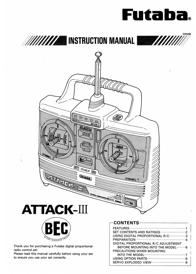
FUTABA ATTACK User manual

Futaba
DIGITAL PROPORTIONAL
RADIOCONTROL
NewATTACK-BFR
&ASP SYSTEM
NewATTACK-R
SYSTEM
NewATTACK
SYSTEM
•The NEW ATTACK,NEW ATTACK-Ris a highperformance 2 channel digital proportional
R/Cset based on the acclaimed ATTACKandhas a built-in BEC (Battery Eliminator
Circuitry) system.
Since the power receiver andservo power is supplied from the running
Nicdbattery, there is notroublesome wiring and the vehicle can bemade
lighter.
•TheNEW ATTACK-BFRis the newest 2 channel digital proportional R/Cset with a built-
inASP (AdjustableSafety Position) system, plus the functions of the NEW ATTACK.
Itis a safety system which protects the vehicleagainst loss ofcontrol due
to a discharged Nicd by detecting a drop inthe voltage of the running
Nicdbattery which isa shared power supply andstops the vehicle.
Thank you forpurchasing a Futaba digital proportional radio control set.
Please read this manual carefully before using your set.
CONTENTS
CONTENTS AND RATINGS ............2
TRANSMITTERFP-T2NBL, FP-T2NBR AND
FP-T2NBFR ......................2
LOADINGTHE PENLIGHT BATTERIES. .3
STEERINGTRIMLEVERADJUSTMENT..3
THROTTLESTICK NEUTRALLEVER
OPERATION
....................
4
CRYSTAL
REPLACEMENT
...........
4
SWIVEL
STICK
SETTING
...........
4
RECEIVERAND SERVOS.............5
USING
THE
FREQUENCY
FLAG
......
7
ASP
SETTING
...................
8
ASP
OPERATION
.................
9
IF ASP OPERATES..............
10
WHENVEHICLEDOES NOT RUN ....
10

FEATURES OFNEWATTACK NEWATTACK-R AND NEWATTACK-BFR
TheNEW ATTACK, NEW ATTACK-R hasaBECfunction.
The NEW ATTACK-BFRhas BEC & ASP functions.
•The
BEC (BatteryEliminator Circuitry)
system
is
a
highperformance constant voltage
circuit (regulator).Since the running Nicd battery can also beused asthe receiverservo
power supply, thereis notroublesome wiring and the vehiclecan bemade lighter.
(Installed inNEW ATTACK,NEW ATTACK-Rand NEW ATTACK-BFR.)
•The
ASP (Adjustable
Safety
Position)
system
prevents
loss
of
steering
control.
It
is
a
safety
system
which protects the
vehicle
against
loss
of control due
to
a
discharged
Nicd
by detecting a drop inthevoltageof the shared power supply Nicd battery and auto-
matically
sets
the
throttle
servo
to the
drive
motor offposition
preset
at the transmitter
then allows steering with the remaining power before steering control islost. Whenthe
voltage ofthe running Nicdbattery recovers,ASP is automatically reset and the normal
running functions arerecovered byturningonthetransmitter power switch.(Installed
inNEW ATTACK-BPR)
World's firstsafety system that allows running ofthe vehicle up to the finish
linewhile using the capacity of the power supply tothe fullestwithout a loss of
steering control even when the voltage ofthe runningNicdbattery drops.
•Transmitter is Built-in servo reverseswitches. (New ATTACK-R,NEW ATTACK-BFR)
TRANSMITTERFP-T2NBL/T2NBR/T2NBFR
SERVOFP-S128
SMALL,RUGGED, HIGH NEUTRAL SERVO
•ASP(AdjustableSafetyPosition)systemallowssafe
recovery without a loss of steering control. (T2NBFR
only)
•Newswivelsticksystemthatallowsselection
ofthe
stick leveroperatingdirectionover a range of10°.
•Racingspecificationshort
aluminum stick lever makes
operationextremelyeasy.
•New
neutral
lever
allowssettingof
the
neutral
position
of thethrottlestickintwostages.Perfectlymatched to
thethrottlepositionof motor and engine cars.Thestick
can be changed toa ratchetsystemby installing an
optionalslider.
•
Servo
reverse
switches (steering
& throttle).
Since each servo canbe switched between forwardand
reversefromtheoutsideofthetransmitter,linkage
hookup is extremelyeasy.(T2NBR,T2NBFR)
•Level meter shows thestateof thebatteryat a
glance.
•Crystal
can bechangedfrom the outside. (Except 72.I
75MHz)
•Hook. Optional neckstrap can be used.
RECEIVERFP-R102GF
•BEC(BatteryEliminatorCircuitry)systemallows
sharing of therunning Nicd batteryand eliminatesthe
need fora regulatorand diode.
•High
performance2 channel
receiver
with
ASP system
when used withthe proper transmitter.
•Crystalsocketuses a new typeof highly reliable sub-
miniaturepins. Reliabilityisincreased and the crystal
can bechanged fromthe outside.
•Skewtypearmaturemotor.
Movement of the trimmer byeven onenotch istracked
bya skewtypemotor which displays a performance
near thatof a corelessmotor.
•New indirectdrivepotentiometerimproves
vibration
and shock resistanceand neutralaccuracy.
•Futabalow-powercustom1C providesextremely
high
torque,narrowdead band, and superiortracking.
•Fiberglass reinforcedPBT (polybutyleneterephthalate)
injectionmolded servocase is mechanically strong
and
invulnerabletoglowfuel.
•Strongpolyacetalresinultra-precision servo gearfea-
tures smooth operation, positive neutral, and very little
backlash.
•FiberglassreinforcedepoxyresinPC board withthru-
the-holeplatingimproves servo amp vibrationand shock
resistance.
•Three pinconnector eliminates faultycontact and im-
proves reliabilityagainstvibrationand shock. Housing
has a reverse insertionpreventionmechanism.
•Specialgrommet simplifiesmounting
of the servo and
has an excellentcushioning effect.
•Sixspecial adjustablesplined horns.
•High48.7oz.jn(3.5kg-cm)maximum output torque
allows use inalmost any model.
1
CONTENTSAND RATINGS
Ratings are subject to change without priornotice.
Transmitter
Receiver
Servo
Batteryholder
Others
FP-T2NBL x 1
FP-R102GFx1
FP-S128x2
R2-BSS-N x 1
FP-T2NBR x 1
FP-R102GF x 1
FP-S128x2
R2-BSS-N x 1
FP-T2NBFRx 1
FP-R102GFx 1
FP-S128x2
R2BSS-N x 1
Switch, frequency flag, spare horn
TransmitterFP-T2NBL/T2NBRT2NBFR
Operatingsystem
Transmitting
frequency
Modulation
Powerrequirement
Current drain
2nick
27MHz, bands1 to6 72, 75MHz
AM (Amplitude Modulation)
12.0V, penlightbattery x 8
170mA
Controlsystem
Operatingangle
Power
requirement
Current drain
(IDLE)
Output torque
Operating speed
Dimensions
Weight
pulsewidth control
Oneside45°ormore
4.8V
-6
6.0V.8mA (atIdle)
48.7 oz.in. 13.5kg-cm)
0.24 sec/60
16x08x1.6in.
(40.5x 20x 40.5mm)
1.92oz.153g)
SERVOFP-S128
ReceiverFP-R102GF
Receiving
frequency
Intermediate
frequency
Selectivity
Receiving range
Power supply
Dimensions
Weight
27MHz band.bands1 to6
72.75MHz
455kHz
3kHz/-3dB
550yards(500m) on theground
when usedwithFP T2NBLIA1 the
best
radio
wave
condition
of
environment)
4.8V to
8
4V
7.2V/13mA.4 8V/33mA
1.46x2.19x0.75in
(37
x
55.5
x
19mm)
1.34
oz
138g)
BEC & ASP functions
TRANSMITTERFP-T2NBL/T2NBR/T2NBFR
•Nomenclature
•The
name
of
each
part of
the
transmitter
is
shown in the figure.Learn them beforeope-
rating your set.
When running the vehicle, extend the antenna
fully.
Before using theset, check the remaining
battery capacitybychecking the level meter.
GoodCaution Nogood
Change the battery.
2
Servo reverseswitches
(NEWATTACK-R,NEW ATTACK-BFR)
Handle
Level meter
Antenna
Frequency flag
Neutrallever
Throttle trim
Throttle stick
ASPsetting
trimmer
ASPsetting
switch
(NEW ATTACK-BFRonly)
Transmitter
crystal holder
Power switch
Steeringtrim
Steeringstick
Hook

•LOADINGTHE PENLIGHT BATTERIES
•Remove the battery cover atthe rearandinsert eight penlight batteries inthe correct polarity.
Remove thecover bypush-
inghereandsliding down.
Loadthe eight pen-light
batterieswhilepayingcare-
fulattention to their-polarity.
•Extend the antenna fully andset the powerswitch to ON.
The level meter pointer should deflectto the silverzone.Ifthepoint-
erdoes not move, or moves verylittle,checkforpoor batterycon-
tact,incorrectbatterypolarity,or faultybatteries.
•If the pointerof the level meter deflectsto the red zone, the range of
the radio waveswillbecome short.When the pointer drops tothe
boundary between the silverand red zones,change thebatteries.
•The
trim
levers
are
used
tofine
adjust
the
steering
angle.
They
are
used to adjusttheneutralpositionand forcorrectingtherunning
posture afterthe mechanism is mounted. Aftertestrunning, make
corrections withthe rod adjuster, etc. and operate the set with the
trim levers inthe neutral position as muchas possible.
•Servo reverseswitches
(NEWATTACK-R.NEWATTACK-BFR)
•Thisswitch makes servo rotation to another-
direction.
•Afterfixedservos onto your model, and found
thatrotation iswrong-way, switch to another
direction.
•Servo reverse switchesare located atbottom of
Transmittercase likedrawing below:
•Steering trim lever adjustment
Normal Reverse Normal Reverse
Steeringservo
reverse
switch
Throttle
servo reverse
switch
When vehicle was runstraight •
Whenvehicleturns
to theright
Move the trimlever slowly
to the leftso that the ve-
hiclerunsstraight.
When vehicle turns
to the left
Move the trim lever slowly
tothe rightso thatthe
vehicle runs straight.
When vehicle was run straight.
•Adjust thetrim leverso that the vehicle runs straight ona smooth road.
Thethrottle trim leverisusedto fine adjust the speedcontroller stop position, etc.
3

•THROTTLESTICK NEUTRALLEVEROPERATION
•The
neutralpositionof thethrottlestick(engine
control
stick)
at
the
left
side
canbe
selected
in
two
stages
by
moving
the neutral lever as shown inthe figure.
When neutral
lever up
When neutral
lever down
Ifthe neutrallever is moved, the
neutralposition ofthe stick
levercan beadjustedin two
steps as shown inthefigure.
When the neutral lever isup, the
throttlestickcan beadjustedto
atotalof 54°, 27" up and 27°
down, fromthe neutralposi-
tion. This positionisbest for
electriccarsand othermodels
withwhich the center of the
speed controller isthe neutral
position.
When the neutral lever isdown,
the throttlestickcan bead-
justedtoa totalof 54°, 36°up
and 18°down (2-to-1),fromthe
neutralposition. Thisposition is
best forengine-drive carsor
other models withwhich the
speed controller neutral position
isoffset.
•CHANGING THE THROTTLESTICK FROM A
SELFNEUTRALSYSTEM TO A RATCHET
SYSTEM
•Whenchanging the throttle stick from a self-neutral
systemto a ratchet system,install the optional slider.
Then, remove the spring and swingarm.
Twist with long-nose
pliers.
Remove the
springand
swingarm.
Install the optional
slider.
•CRYSTALREPLACEMENT
•Whenchanging the band, remove the crystalholderand
change the crystal.(Except72. 75MHZ)
•Futaba Digital Proportional Frequencies (FOR
U.S.A.)
•The frequency of Futaba digital proportional sets can be
changed among bands (1)~ (6)on the27MHzband only.
•However,a 27MHzband set cannot bechanged to72MHz
band, and viceversa.
•Therefore,always,attach the correct frequency flag to
the end of thetransmitterantenna. Each frequency band
has itsown designated color,as statedabove. The fre-
quency flagis intended foridentificationpurposes.
•Alsochange the frequencyflagwhen frequencyis
changed.
•Futaba pairedcrystalsarepreciselymatched.Alwaysuse
aFutaba crystalset (transmitter,receiver)when changing
the frequency.
•Itisillegal to change crystals of transmitter on the 72-75
MHz bandsinthe U.S.A.
Frequency ChannelNo.FlagColor
•SWIVELSTICK SETTING
•To adjustthe operating directionofthe stick lever, loosen
the fourscrewsshown in thefigureand turnthe stick
body and setit tothe best position.Aftersettingthe
stick,retighten the fourscrews.
(1)
Loosen these four screws.
(3) Tighten these four
screws.
(2) Selectthe angle by
turningthe stickbody.
Stick lever can beset
within thisrange.
5°.5°
4

system
sets
with
a
receiver
with
shared
power supply
regulator.
The
mark isdisplayed on thefront of the receiver of BEC
RECEIVERFP-R102GFAND SERVO FP-S128
The Futaba BEC system and BEC & ASP system canalsousea commonpowersupplywith the conventional four
penlight batteries system(separate power supply).
5
(75MHz-OPTIONAL)
(3) When
motor
car
uses
an
ordi-
nary common power supply
chassis
Redcommon2P
connector
(Female pins)
Buy the redcommon 2P
connector fromthe kit
manufacturerand connect to
the controller.
Pin1: Minus
Pin2: Plus
(2) When motor car uses a speci-
al BEC systemchassis(com-
mon power supply specifi-
cations)
Connect to the red common
2P connectorofthe control-
ler.
Receiver crystal
Steering servo
Throttle servo
Receiver FP-R102GF
ON
OFF
Switch
Antenna wire
Redcommon2P
connector(male pins)
Connect the servo and switchas
shown in the figureand extend
the transmitter and receiver ante-
nna
fully.
(Female pins)
Redcommon
2P
connector
Connection tothisconnector
(1)When chassis power supplyof
engine ormotor car isseparate
Wrappedwith
rubberbands.
(Female pins)
Controller
Redcommon2P
connector

•Acommon power supply regulator and diode may also besupplied with the speed controller, depend-
ingonthevehicle kit.Sincetheycausea voltage drop,always remove them.
TO BUYERSOF THE NEW ATTACK-BFR(FP-R102GF)
When using a Futaba motor controlamp (MC-106,
106B, 108,109,110, etc.)instead ofthespeed
controllersupplied withthe vehicle, turnoffthe
ASP system as shown inthe figure.
•Setthe transmitter power switchtoON, then set thereceiverpower switchtoON. The servos stopnear the neutral
position. Operatethe transmittersticksand checkif each servofaithfullyfollowsoperationofthe sticks.
R102GF ASP
release
connector
Insert the ASP releaseco-
nnector packed withthe
set at this2P connector'
(male pins)on theprinted
wiringboard.
From transmitter
when switch turned
on
From receiver when
switch turned off
•Connect the pushrod to eachservo horn, then check if the direction of travel of eachservo matches the transmitter
operation.
When transmitter
stick lever set tothe
right
Vehicle also steers
to the right
6

•Operate each servo over its fulltraveland check if the pushrod binds or is tooloose.Applyingunreasonable forceto
the
servo
horn
will
adversely
affect
the
servo
and quicklydrain
the
battery.
Be
especially
careful
when using
8.4V.
•Alwaysmake the fullstroke(includingtrim)of theservohornssomewhatlargerthan thefulltravel.Adjustthe
servo horns so that they move smoothlyeven when the trim lever and stick are operated simultaneously inthe same
direction.
•
Be
alertfornoise.
Alwayssolder a noise killing capacitorto the running motor.Ifmetal partstoucheach other due to vibration, noise
will
begenerated and
cause
the receiver
servos
to
operate erroneously.
We
recommend the
use
of
noiseless
parts.
•Even
though the receiver antenna
wire
is
long,
do
not
cut
or
bundle
it.
The
range
of
the
radiowaves
will
beshortened.
Receiverantenna
wire
Woodscrew
Rubber bushing
Grommet
Install
the
servos
firmly.
Install
the servo to the servo trayas
shown inthefigure.Inother
cases, install the servoas des-
cribed in the model manufac-
turer'smanual.
R102GF
Scissors
•A spare horn isprovided. Useitas required.
•Wrap
the receiver
in
sponge
rubber and
wrap
rubber
bands
around
the
sponge
rubber.
Mount the
receiver
so
it
is
not exposed to vibration,does not touchtheframe,and does not move.
•When
the
receiver
is
installed on
a
board or
used
where
it
may
be
splashed
with
mud
and
water,
place
it
in
a
plastic
bag,etc.and wrap a rubber band around theopen end ofthe bagto waterproof anddustproof the receiver. Afteruse,
remove the receiver fromthe bag toprevent condensation.
•Use therubber bands wrapped aroundthereceivertohold theservoand switchleads.
•Aftermounting is complete, recheckeach part,thencheckthetransmittingrange bymaking the transmitter antenna
as short as possible and extendingthereceiverantennafullyand operatingthe set froma distance of 20mto30m.The
movement of each servo should followthe movement ofthe transmittersticks.
•The crystalcan bechanged fromthe outside of the receiver case.Alwaysusea Futaba transmitter andreceiver crystal
pairas the replacement crystals.
•USING THE FREQUENCYFLAG
Insert the frequency flag
into the flagholder as
shown here.
72/75MHZ Flag
Staple or glue withcyano-
acrylateribbon here.
Theflag can beattached to
and removed fromthe end
of the antennawithone
touch.
•Thehookisfor the optionalneckstrap. Itisconvenient when hangingthe transmitter from your neck.
7

The BEC system that makes iteasy even for beginners to lightenthe ve-
hiclebymeans of a shared power supply isalready well known. Theuni-
que
Futaba
ASP
system
is
built
into
the
BF
series
was
completed by
advancing this BEC system one more stepand pursuing greater safety.
ASP detects a drop inthevoltage and moves the throttle servo automati-
callytothe drive motor off position which ispreset at the transmitter
before steering control islostbya drop inthe Nicd battery voltage while
thevehicle isrunning.Itisalso the world's first revolutionary system that
allows steering operation with theremaining power. (Patentpending)
•ASP setting (NEW ATTACK-BFRonly)
Before running,set ASP to the controller stop posi-
tion.
•Ifthe controller isnotsetto the stop position,when the
running Nicd batteryvoltagedrops, the throttleservo
may stopat a positionother than thestoppositionand
the vehiclemay run wildbecause the throttleservo can-
not becontrolledfromthe transmitter.
Forward
Stop
Reverse
Since the stop position
differswiththe chassis
manufacturer,checkit
when connecting the
linkage.
Throttle
servo
Controller
1.Setthe transmitter andreceiver power switches to on
and check the steeringand throttleoperations.
2. a)Set the ASP settingswitchtotheSET side. ASP setting
b) Turn the ASP settingtrimmerat theleft
sideof the
trimmer
switchwitha littlescrewdriver.
c) Since thismoves the throttle
servo, set sothat it
stops at the stop position of the connectedcontrol-
ler.
ASPsetting
switch
NORM
SET
ASP
3.Then complete adjustment by setting the ASP setting
switchtothe NORMside. (Iftheswitchisnot switched
tothe NORM side, the throttleservo will not becont-
rolledbythe throttle stick.)
NORM
SET
NORM
When settingASP When ASP setting is
complete
Turn
with
a
little
screw-
driver
When the ASP setting
trimmeris turnedinthe
arrowdirection,the
throttleservo turns in
this direction.
Throttle servo
•When the Nicd battery voltage drops, the throttle servo ismovedto the presetposition and the drive motorisstopped
automatically.
8

•STARTING
Whenthe ASP operates and the vehicle
stops as soon as itstartsto run, there is
troublesomewhere.
•Since the vehicle,running Nicd battery,
motor, etc. isabnormal when ASP was
operated, check again.
•IF ASP OPERATES
(Vehicle trouble)
•If
somethinggetscaught inthe gears orthe
tiresdo not rotatesmoothlyand an over-
currentflowsin the motor,ASP may operate.
Whenusingthe common power supply diode
and regulatorwitha vehiclewithoutBECspe-
cifications.releaseASP.Otherwise,ASP will
operateimmediately.
•Since the Futaba and FP-R102GFreceivers
have theBEC systembuilt into them,
adiode and regulatorarenot connected.
(Running Nicdbattery trouble)
•Whenthe Nicd batteryis charged insuffici-
entlyor is old, ASP will operate.
Insufficient charge
Capacity of used
Nicdislow.
(Motortrouble)
•Whena modified motor, highpower motor,
ora motor whose angle cannot beadjusted
isused and when themotor is accelerated and
reversed suddenly, ASP may operate.
•Whenusing high power motor,set ASP to
OFFwithASP releaseconnector.But when
settingASP to OFF,becarefulthatthe ve-
hicle may run away if the capacity of run-
ning Nicd battery runs short.
R102GF
ASP
release
connector
Insert the ASP release connector
packed withthe set at this2P
connector (male pins)on the
printed wiring board.
9

•IF ASP OPERATES
•If ASP systemoperates and the vehiclestops.
Set to OFF once
set thetransmitterpower switchto OFF
once and set ittoON again.Then ASP
system
stopsworkingand youcan startagain.
•Restartrunning time depends on the variety
and condition ofvehicle,motor, and battery.
Becareful about that.
ON
OFF
Setto ON again.
•WHEN VEHICLE WILLNOTBE USED
Besure and release the connector ofrunning
Nicd batteryexceptwhen you are on the way
to the startingline.
When not using the
connector,set the
switchto OFF.Release the connector.
FP-S128
No.
1.
2
3.
4.
5.
6.
7.
8.
9.
10
11.
12.
13.
14.
15.
16
17.
18.
19.
20.
21.
22.
Part Name
Uppercase
Middlecase
Bottom case
Metal bearing
Potentiometer
VRdrive plate
Motor
Motor pinion
Motor mounting
screw 2x3
1stgear
2ndgear
3rd gear
Finalgear
Intermediate shaft
2ndshaft
Servo horn D
Horn mounting screw
2.6x8
Printed wiring board
S128...3PBWRB300
Leadwire packing
Casemountingscrew
Nameplate
Part No.
FCS28
S04134
139995
S02753
S91212
S02461
J
50002
FGS-28
S02495
S02494
FSH-6W
FSH-41
AS1202
FPC-8M
S90045
J50400
S80700
Thefollowing splinedhornsare optional.
HORN A HORN B HORNCHORN D HORN E HORNF
•SPLINEDHORNS
This horn permits shiftingof the
servo neutralposition at the servo
horn. Settingand shiftingthe neutral
position
a)
Angledivisions
1) The splined horn has 25 seg-
ments. The amount ofchange per
segment is;360-25=14.4°
2)The minimum adjustableangleis
determinedby the number of arms or
number of theholes. For fourarms,
the minimum adjustableangle is:
b) Effect
To shiftthe holes center line to the
right (clockwise)relativetobaseline
A,shiftarm2 tothe positionofarm
1and set itto the position closet to
baseline A.
[Example]For a fourarm horn, the
angular shiftper segment is14.4°.
The shiftto the right is90°- (14.4/
6) = 3.6°
To shiftby thesame angle in
the
opposite direction,use the opposite
armnumber.
For a sixarmhorn, turnthearm
counterclockwiseand set arm2 to
the position of arm1.The adjustable
angle is 60°- (14.4 x 4) = 2.4°.
Arm3 shift4.8° tothe right,arm6
shifts2.4° tothe left,and arm 4
shifts7.2° to the right and left.
10

YourNEW FUTABADigital ProportionalR/Csystem
is guaranteedagainst defectsinworkmanshipand
materialfor180days fromthe date of purchase when
the attachedregistrationcard isreturned to uswithin
ten days of purchase.
This Guaranteeis nulland void ifthe R/Csystem has
been improperly handled, damaged ina crash, or
tampered withand does not cover thereplacementof
plastichousings or electroniccomponents damaged
due to the use of improper voltages.
When serviceis required,pleasetakeyourequipment
to yourlocal authorizedservicestationor ship it
directlyto us. Allpostage, shipping, and insurance
charges must bepaid bythe user.
•Whenrequestingrepairof troublethathasoccurred
suddenlyoffromlong use, describe the trouble
symptomsin as much detailas possible.
This willfacilitatedetectionof the trouble point and
shortenthe repair period greatly.
•Defectscaused byfaultymaterialsor workmanship
willbecorrectedfreeof charge.
•Thislimitedwarrantyisnull and void ifthe set has
been tampered withor disassembled.
Referto warrantystatementfordetails.
WORLDSALES& SERVICEFACILITIES
Australia: FUTABASALESAUSTRALIAPTY.LTD., Lebanon:
MELBOURNETEL:211-4788
Argentine: MODE LISMO AERONAUTICODEGA SRL.New Zealand:
BUENOS AIRESTEL:393-2299
Canada:UDISCOLTD., MONTREAL
TEL:481-8109 Norway:
Chile:HOBBYLANDIA,SANTIAGO
TEL:743957 Singapore:
Denmark: FUTABAIMPORTDENMARK,
COPENHAGENTEL:02-91-0101SouthAfrica:
England:RIPMAXLIMITED,LONDON
TEL:01-8048272Spain:
Finland:NORETRONKY.HELSINKI
TEL:90-488880 Sweden:
Greece:C. & G. MACRIYIANNISCO., PIRAEUS
TEL:021-3604 391 • or 021-41 76191 U.S.A.:
HongKong: RADARCO.LTD.TEL:3-680507
Italy: RADIOSISTEMISRL,Carrara W.Germany:
TLX:500494 FORTIMI
FAX:0039-585-52247
KHAIRALLAHMODELCRAFT,BEIRUT
TEL:326-681
AMALGAMATEDWIRELESS
(AUSTRALIA)N.Z. LTD. WELLINGTON
TEL:58-979
HARALDLYCHECO. A/S,Drammen
TEL:(03) 833970
SINGAPOREHOBBYSUPPLIES
TEL:533-0337
REDIPAK(PTY.)LTD.,
JOHANNESBURGTEL:21-1511
HOBBY& TOYINTERNATIONAL,
VALENCIATEL:(96)35723 93
RADIOCONTROLCENTER,
JONKOPINGTEL:036-145360
FUTABACORPORATIONOF AMERICA,
CALIFORNIATEL:213-537-9610
ROBBEMODELLSPORTGMBH,
GREBENHAINTEL:06644-870
FUTABA
CORPORATION
OF
AMERICA
555 West VictoriaStreetCompton, California90220 U.S.A.
Phone: (213)537-9610 Telex:23-0691227 Facsimile:213-637-8529
FUTABA
CORPORATION
Tokyo Office:INAGAKIBLDG., 3F 1-21-3, Kandasudacho, Chiyoda-ku,
Tokyo,Japan.
Phone:(03) 255-6811
This manual suits for next models
5
Table of contents
Other FUTABA Remote Control manuals

FUTABA
FUTABA 9ZAP - PART2 User manual

FUTABA
FUTABA 7PX User manual

FUTABA
FUTABA T12FG Technical manual

FUTABA
FUTABA 6EX-2.4GHZ User manual

FUTABA
FUTABA FP-G132 User manual

FUTABA
FUTABA 7C - User manual

FUTABA
FUTABA FP-2PB User manual

FUTABA
FUTABA T4PM User manual

FUTABA
FUTABA 3VCS User manual

FUTABA
FUTABA T12Z Technical manual

FUTABA
FUTABA T32MZ Manual

FUTABA
FUTABA 8J User manual

FUTABA
FUTABA FP-5FG User manual

FUTABA
FUTABA T10PX How to use

FUTABA
FUTABA 4PK-2.4G SuperR User manual

FUTABA
FUTABA 8FG User manual

FUTABA
FUTABA T12K User manual

FUTABA
FUTABA FX-20 User manual

FUTABA
FUTABA S.BUS2 10J User manual

FUTABA
FUTABA 2PEKA User manual