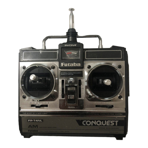
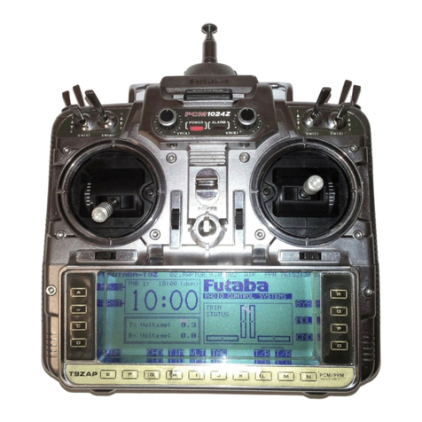
FUTABA FP-4DN User manual

New FUTABA
DIGITAL PROPORTIONAL
RADIO CONTROL

INDEX
Features........................................................................ 1
Specifications
............................................................
2
Transmitter
operation
................................................
3
Handling the
Receiver
& Servos
.................................
6
Ni-cads batteries &
re-charging....................................
8
Preca
tions,
test & installation
....................................
9
Guarantee..................................................................
12
Factory repair service
................................................
13

FUTABA NEW PROPORTIONAL R/C FEATURES
TRANSMITTER
1.AllFutaba New Proportional Models are designedand manufactured to theidenticalstandards andspecifica-
tions.
Thereforemixingwithother Futabareceiversand servoswillnot affectthe operation.
2. Frequency changes are easilyaccomplished,because of the plug-in socket forthe crystals.
3. ThrottlecontrolLever location canbeeasilychanged from
left to right side.
4. Neck strapand Hook isprovided forconvenient handling.
RECEIVER
1.Because of theNew 8-BIT integrated circuit device,
usedinall FutabaReceivers, all Futaba Propo. Systems
aresupplied with 6 channelcapacityreceiverFP-R6D.
2. Light weight and miniaturizedby NEW 3-WireMini-Block connector.
3. Stableoperationfrom 4V to6.6V resultingfrom utilizationof the power
saving circuits.
4.Frequency change can beeasily accomplished without opening the receiver case because of the uniqueoutside-
mounted crystalsocket.
5. Strong rejectionof spurious signalsby utilizationof a double tuned RF pre-selector circuit.
6.Shielded RF and Oscillator coilsprovide strong rejectionof spurious signals.
7. Accidental touching of Futaba Transmitter andFutaba Receiver antennas will notaffect the normalop-
eration.
SERVO
1.Since the FP-S5, FP-S5L, FP-S4 arealldesigned and manufactured
to identical standards, they will display
their maximum capabilityeven when mixedwith other FutabaModels.
2.Withthe use of Monolithic intergratedcircuit,Futaba BA-606 and BA-607 Servo AMPS are small insize,
light weightand sturdy withhigh output torque.
3.Inthe BA-607, the 12-pin singleEnd-lineMonolithic 1Ccontains a low current drain. High resolution. Temper-
ature compensated Low-voltagecircuitwhichallows operation down to 4V withoutcreating interference
between adjacentServos.
4.Inthe BA-606, the 9-pin single end-line integrated circuit isused.This circuit contains; 2 specially made high
out-put current(500mA) transistorsof the PNP type,2 NPNtype transistors, 4 Diodes,4 Resistors, a total of
12integrated devices ina single package.
5. Atidle, low currentconsumption. (8
mA).
6.High out-put (torque) 2 kg/cm.
1
TRANSMITTER OPERATION
With
the FP-4DN,
a
two-stick
control
will
operate:
1.Throttle
2. Aileron
3. Elevator
4. Rudder
Withthe FP-5DN, inaddition tothe above
mentioned operations, a snap-switchis
provided forthe landing gear or other
suitableoperations.
With the FP-6DN, aside from the 5 move-
mentsabove, an additional control(vol-
ume typecontrol)is added on thefront
panel forthe 6th control (variablemove-
ment).
Operatingprocedures for the FP-4DN, FP-
5DN, FP-6DN arethe same as they are
designed and Manufacturedtothesame
specifications.
Asan additional feature, allFutabaPropo.
Modelsareprovided with two(2)setsof
knobs(longand short),tosuityour re-
quirements. To changeknobs, pull firmly
offtheBlackPlasticKnobs fromthecon-
trolsticksand replace withthespare plas-
tic knobs provided inthe Kit.
Aneck strap too is provided for your con-
venience.
3

The front panelcontrols on the Transmitters are shown inthe Diagram below anditissuggestedthat themanipu-
lation of these controlsbewell mastered.
FP-T4D
(forFP-4DN)
4-CHANNEL
FP-T5D
(for FP-5DN)
5-CHANNEL
FP-T6D
(forFP-6DN)
6-CHANNEL
FP-T5
(for
FP-5)
5-CHANNEL
4

1.FP-4DN,FP-5DN, FP-6DN and FP-5Transmitters are equippedwith a built-in transformer-type charger for
maximum safety and provided
with
8/450
mAH
Nickel
Cadmium
Batteries for dependable operations.
2.With the antennafirmlyinplace, turn the switchon and the Meter needle willpoint to10or more on the Dial.
This is an indication thata Radio signal is being radiated.Ifthe meter needle does not move, check fora pos-
siblebadconnection inthe powersupply unit.
3.When the meterneedlepoints below10,this indicates that the battery isnotsufficiently charged.
4.Pleasebeaware that whenever the meterneedle falls below10,the area covered bythe signalisdiminished.
5.
Along
sideand
below
each
control
sticks are
two
(2)small Blacklevers. These allow
"trim"
of all
four
main
controls. You canadjust(Trim)these levers for fineadjustments for all four (4)operations suchas throttle,
ailerons, elevatorsand rudder.
6.FREQUENCIES - Available inMHz.
(Available Futaba paircrystal Tx/Rx)
27 MHz Areas
26.995 (Brown)
27.045
(Red)
27.095 (Orange)
27.145 (Yellow)
27.195 (Green)
72
MHzAreas.
*72.080 (Brown/White)
72.160 (Blue/White)
*72.240 (Red/White)
72.320 (Violet/White)
*72.400 (Orange/White)
72.960 (Yellow/White)(**)
*75.640 (Green/White)(**)
Remarks: Mark * = ModelAircraft useonly.
Mark (**) = Factory tuned convertion ofcrystal isrequired.
5

HANDLING THE RECEIVER AND SERVOS
1. The FP-R6D receiver incorporates an 8
Bit integratedcircuitand is made into
6-channeloperation. The same inte-
grated circuitis alsoused forFour (4)
and Five (5) channel operation.
2.The Block connector socketsthat con-
nects the differentServos are an inte-
gral part of the receiver.
3.The Block Connector sockets are po-
larized and each position is designated
on the receivercase.Thereforecheck
carefullybefore connectingtheServos.
Particularlycaremust be takensince
thepower supply relayconnectoris
Red and the Aileron relay connector
is BLACK.
4. Since eachServo is built tothesame
specifications,any Servo can be used
for any purpose.
5.There isa FP-S5L (Reversible Servo
Red Label) included ineach set. This
Servo is convenient for throttle control
onshoulder wing models.
6

6.Connectors are made as shown inthe above diagram. Please make certain that each connector isfully plugged
inandthat the Aileron section etc., and the power supply switch harness iscorrectlyidentified.
7. Aftermaking certain thatthe connections arecorrectaccordingto the above diagram,turnon the transmitter
switchand then putthe receiver switch to ONposition. Atthis pointeach Servo will stop at the Neutral
position.
8.Move each stick andTrim leverand check to seeifthe specific Servo isactuated correctly.
9.When each section istested for movement, please make certain that boththe Transmitting and Receiving
antennas arefullyextended.IftheTransmittingantennais shortened and the Transmitter switch isleft ON
for more than 5 minutes, the transistors inthe Transmitterwill bedamaged.
10.
Ifthe system does not operate after completely assembling the batteries, switchharness and Servos for the
receiverand the Transmitter,theproblem may be due to damage during shipment. Do not attempt to open
any ofthe units,butreturn them for exchange.
7

NI-CAD BATTERIES AND RE-CHARGING
FP-4DN,FP-5DN, FP-6DN and FP-5 Transmitters areequipped with eight (8)pen-lighttypeNi-Cad batteries.
FortheReceiver & Servos, Four(4) Ni-Cadbatteries are providedinthe set.
Priortoeach usageNi-Cadbatteries should be chargedfor 12to 15hours. Ifthey have notbeeninuse for some
time,the batteriesshould becharged for about 20 hours before use. Thereis no harm ifthe chargingtime is
slightly exceeded.
When Ni-Cad batteriesarecompletely charged, you can ordinarilyexpect about 100minutesof useduring a given
day, about 10controlsessions of 10minutes each.
Normally Ni-Cad batteries will holdan averagevoltagehowever, afterthisgiventime period of use, thevoltage
will drop suddenly soitisrecommendedthat following 7 or8 control sessions of use,a voltage check bemade
without fail.
Forcharging the Ni-Cad batteries,connections should bemadeas shown inthe Diagram.
8
For charging either TRANSMITTER onlyorRECEIVER,both'A' & 'B'plugsmustbepluggedintoTransmitter bottomas
shown inthe above diagram.

TO CHARGE TRANSMITTER BATTERIES
1.Oneend of thechargingcord should be plugged into"A"
atthe bottom of the Transmitter and the other end
into the wallsocketof the household electricpower outlet (AC115V).
TO CHARGE THE RECEIVER
1.Usereceiver chargingharness (red3 pinconnectorand Plug)as shown in diagram.
Red3 pinconnector should beplugged into battery unitand the other end with plugintoTransmitter Marked
"B".
PRECAUTIONS FOROPERATIONAL
TEST AND INSTALLATION
1. After making certainthatthe Receiver & Servos arehooked upaccording tothe diagram and batteries checked
extend the Transmitterantenna to its shortestlengthand with the receiverantennainextended condition,if the
controls functionsproperlyat the distance of 50 to100feet the system is operatingnormally. However it should
becautioned thatthisshould not continue anylonger than Five (5)minutes, otherwiseit might damage some
components. Never testthe system without attaching theantenna tothe Transmitter as thiswillalso have and
undesirable effecton the instrument.
2.Duringthe installation wrap the receiver well with sponge rubberso that itwillnottouch other mechanisms
orthe aircraftitself.Alsobecareful to preventengine vibrationsfromaffectingthe receiver. Asfor the Boat
use,inaddition, itmight bea goodpractice to cover each unitwith vinylbagandtiedsecurely at each cord
to prevent waterfromentering.
9

3.When installing the Servo, the useof
the Servotrayis veryconvenient.This
isdone according to the diagram.
Please make sure each connector is
plugged incompletely.
Alwaysre-checkthe installation of the
ServoHorns and Rods tomake sure
thattheirmotion matchesthemove-
ment ofthe Transmittercontrolstick.
Use thereversibleServo(FP-S5L)for
Throttlecontrolon shoulder wing
models or foractuatingthe rudder
and nose gear, howeverthis Servo
can notbeused for Aileron.
10

4.Aftersetting the pushrods on each Servo,usingtransmitter, actuate each Servo fully from leftto rightmaking
sure the rod will nothang-up on any position,otherwise the excessive current flow thru Servo will damage
the unit.
5. Noise (interference) signals shouldbeavoided. For example, iftwo metal parts are inintermittent contact with
each other due to engine vibrations,noise signalsaregenerated.Whenthesesignalsenterthereceiver,unex-
pected movements of theServos canresult. Therefore one of the metal surfacestouching each other should
becovered with an insulating material.
6.When theinstallationis complete, atleast once, by allmeans, visita nearby radio control expert or the deal-
er where the equipment waspurchased and be advisedon proper handling techniquesand other items which
require attention. Itisnecessary while receiving thiscorrect instructionalso, tohavetheinstallationcompletely
checked.
Let's enjoy Radio control by taking the advice of experts and observing the rules of Safety.
11

GUARANTEE
Your NEWFUTABA Digital Proportional R/Csystem isguaranteed
for 180 days from date of purchase against all defects inmaterials or
workmanship. When the attachedregistration card isreturnedto us
within Ten days of purchase.
Guarantee isvoid ifthis R/Csystem has been improperly handled,
damaged ina crash or tampered with. The guaranteedoes not cover
the replacement of Plastic Housings orElectronics components bythe
use of improper voltage.
Inthe event that service isneeded, please take your equipment to our
local authorized service station or ship directlyto us,you are required
topay all postage, shipping and insurance charges.
This will apply only to continental U.S.A. including Hawaii andAlaska.
12

OUT OF WARRANTY FACTORY REPAIR SERVICE
Toinsureprompt service, please follow the instructions listed below.
1.Charge batteries for at least18hours prior to shipment.
2.Returnonly the system, separate from your installation. Removeservos from mounts,remove foam
padding from receiver.
3.
Plugs
orother modifications
which
interfere
with
factory testingprocedures
will
be
returned
to
factory standards at your expense.
4.Carefully pack all components individually with sufficient packing material to preventshippingdam-
age.
5.Includea brief butthorough explanation of all problems andservice required and tape to back of
transmitter. Label servosas to their function.
6.Besure to include your full address and zip inside theboxaswell as outside.
7.Includea packing list of all items beingreturned and double check to make sure allitemsare.
8.Ifyou returndamaged equipment to FUTABA forfactory service FUTABA will estimate the cost
of repair and notifyyou,uponreceiptofyour paymentyourequipment willberepairedandreturn
to
you.
Thiswillapplyonlytocontinental U.S.A. includingHawaii and Alaska.
13

This manual suits for next models
7
Table of contents
Other FUTABA Remote Control manuals

FUTABA
FUTABA T14SG Technical manual

FUTABA
FUTABA 8FG User manual

FUTABA
FUTABA 3PM User manual

FUTABA
FUTABA 14SG User manual

FUTABA
FUTABA T4PM User manual

FUTABA
FUTABA T16IZ Manual

FUTABA
FUTABA 7PX User manual

FUTABA
FUTABA 2PL-2.4GHZ User manual

FUTABA
FUTABA 3VCS User manual

FUTABA
FUTABA 6EX 2.4GHZ Owner's manual

FUTABA
FUTABA FP-3EG User manual

FUTABA
FUTABA 14MZ User manual

FUTABA
FUTABA 3PKS User manual

FUTABA
FUTABA 8FG User manual

FUTABA
FUTABA FP-3PB User manual

FUTABA
FUTABA 2PEKA User manual

FUTABA
FUTABA 10CAP User manual

FUTABA
FUTABA 3GR-2.4GHZ User manual

FUTABA
FUTABA CONTEST-7 User manual

FUTABA
FUTABA T6K-V2 User manual