FuturaSun 3K User manual

- 1 -
INSTALLATION MANUAL
HYBRID INVERTER
Optor Single
3K/3.6K/5K/6K
V 2023.06-MM

- 2 -
CONTENTS
INFORMATION REGARDING THIS MANUAL ............................................................................................................................ 4
HOW TO USE THIS MANUAL .................................................................................................................................................... 4
1. SAFETY WARNINGS .............................................................................................................................................................. 4
2. DESCRIPTION OF THE PRODUCT .......................................................................................................................................... 4
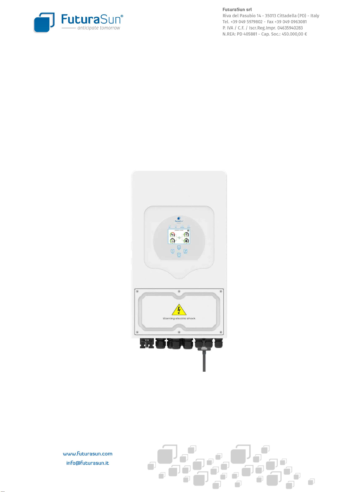
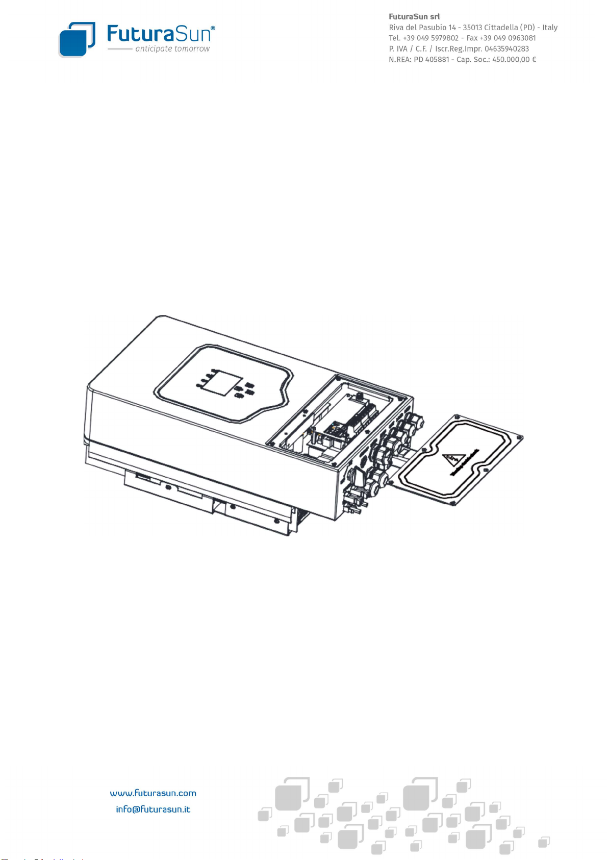
2.1 PRODUCT OVERVIEW .................................................................................................................................................... 5
2.2 PRODUCT DIMENSIONS ................................................................................................................................................. 6
2.3 PRODUCT FEATURES ...................................................................................................................................................... 7
2.4 PRODUCT FEATURES ...................................................................................................................................................... 7
3. INSTALLATION ...................................................................................................................................................................... 8
3.1 LIST OF COMPONENTS................................................................................................................................................... 8
3.2 INSTALLATION INSTRUCTIONS ...................................................................................................................................... 9
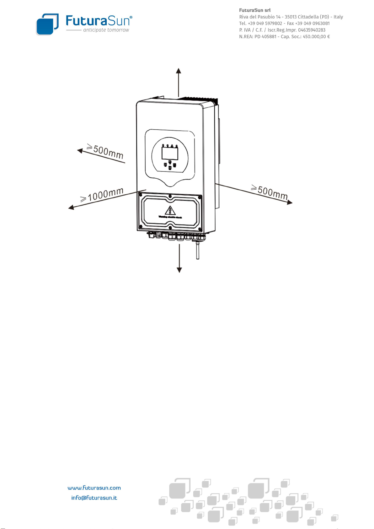
3.2.1 INSTALLATION PRECAUTIONS ................................................................................................................................ 9
3.2.2 SELECTION OF THE INSTALLATION WALL .............................................................................................................. 9
3.2.3 INSTALLING THE INVERTER .................................................................................................................................. 10
3.3 CONNECTING THE BATTERIES ..................................................................................................................................... 11
3.3.1 SPECIFICATIONS OF THE FUNCTION TERMINALS ................................................................................................ 13
3.3.2 CONNECTION OF THE TEMPERATURE SENSOR FOR LEAD/ACID BATTERIES ...................................................... 14
3.4 CONNECTION OF THE GRID AND THE BACKUP LOAD ................................................................................................. 15
3.5 PHOTOVOLTAIC FIELD CONNECTION .......................................................................................................................... 17
3.5.1 PHOTOVOLTAIC MODULE SELECTION AND PHOTOVOLTAIC GENERATOR CONFIGURATION ........................... 18
3.6 CT CONNECTION .......................................................................................................................................................... 19
3.6.1 CONNECTION WITH EXTERNAL METER CHNT DDSU 666 .................................................................................... 20
3.6.2 CONNECTION WITH EXTERNAL METER EASTRON SDM230 ................................................................................ 21
3.7 EARTH CONNECTION ................................................................................................................................................... 21
3.8 WI-FI PLUG CONNECTION ............................................................................................................................................ 22
3.9 DIAGRAM OF TYPICAL CONNECTION .......................................................................................................................... 22
3.10 DIAGRAM OF SINGLE-PHASE CONNECTION WITH PARALLEL INVERTER ................................................................. 23
3.11 DIAGRAM OF THREE-PHASE CONNECTION WITH PARALLEL INVERTER .................................................................. 25
4 OPERATION ......................................................................................................................................................................... 26
4.1 SWITCHING ON USING THE ON/OFF BUTTON ............................................................................................................ 26
4.2 DISPLAY AND SIGNALLING LEDS.................................................................................................................................. 26
5 LCD DISPLAY ICONS ............................................................................................................................................................. 27
5.1 MAIN SCREEN .............................................................................................................................................................. 27
5.1.1 MENU STRUCTURE ............................................................................................................................................... 28
5.2 SOLAR / INVERTER / LOAD / GRID / BATTERY INFORMATION .................................................................................. 29
5.3 ENERGY DATA PAGES AND CURVES ............................................................................................................................ 30

- 3 -
5.4 MAIN SETUP MENU PAGE ........................................................................................................................................... 31
5.5 BASIC SETTINGS ........................................................................................................................................................... 31
5.6 BATTERY SETTING ........................................................................................................................................................ 32
5.7 SYSTEM WORK MODE ................................................................................................................................................. 34
5.8 GRID SETTINGS ............................................................................................................................................................ 36
5.9 CEI 0-21 SELF-CHECK .................................................................................................................................................... 38
5.10 GEN PORT USE ........................................................................................................................................................... 40
5.11 ADVANCED FUNCTION .............................................................................................................................................. 41
5.12 DEVICE INFO .............................................................................................................................................................. 42
6 POSSIBLE OPERATING DIAGRAMS ...................................................................................................................................... 42
7 ERROR MESSAGES ............................................................................................................................................................... 45
7.1 LIST OF ERROR MESSAGES .......................................................................................................................................... 46
8. CONFIGURATION OF THE WI-FI PLUG AND MONITORING APP ........................................................................................ 48
9. TECHNICAL DATA ............................................................................................................................................................... 53
10. APPENDIX I ....................................................................................................................................................................... 54
11. APPENDIX II ...................................................................................................................................................................... 56

- 4 -
INFORMATION REGARDING THIS MANUAL
The manual mainly provides product information, and installation, operation and maintenance guidelines. It does not,
however, include information regarding the photovoltaic sector.
HOW TO USE THIS MANUAL
Read the manual and other related documents carefully before any work on the inverter. All documentation must be stored
carefully and always be available in case of need. Contents may be periodically updated or revised as a result of product
development. The information contained in this manual is subject to change without notice. For a copy of the latest version
of this manual please contact info@futurasun.it
1. SAFETY WARNINGS
This section contains important safety and operation instructions.
Before using the inverter, read the instructions and warnings of the batteries to be installed, and the corresponding sections
in the instruction manual.
Do not open/disassemble/tamper with the inverter. If maintenance or repair is required, contact a licensed professional
installer.
Incorrect installation may result in electric shock and/or fire.
To avoid the risk of electric shock, disconnect all cables before attempting any maintenance or cleaning. Switching off the
inverter alone cannot eliminate the risk of electric shock.
ATTENTION: this product may only be installed by qualified personnel.
Never charge a battery that is below its operating temperature limit.
For optimal operation, use DC and AC power cables with appropriate cross-sections depending on the electrical currents
and powers.
Take great care when working with metal tools in the vicinity of the batteries. Dropping an instrument can cause a spark
or short circuit in batteries or other electrical components, or even explosion.
Strictly follow the procedures in this manual when disconnecting the terminals of the AC or DC connections. Refer to the
“Installation” section of this manual for the details.
Earthing instructions: this inverter must be strictly and correctly connected to a permanent earthing system. The local
requirements and regulations for installing the inverter must be observed.
Short circuits of the AC output and the DC input must always be avoided. Do not connect the inverter to the electric power
supply if the DC input is short-circuited.
2. DESCRIPTION OF THE PRODUCT
This inverter is a multifunctional product: it combines the functions of an inverter, a solar charge controller and a battery
charger to supply low-power electricity without interruption. Thanks to easily accessible buttons, its detailed LCD screen
allows the user to operate and configure the machine as battery charger, with solar/AC charge and flexible input voltages
according to different applications.

- 5 -
2.1 PRODUCT OVERVIEW
1 : INVERTER INDICATORS 7: DRMs PORT 13 : ON/OFF BUTTON
2 : LCD DISPLAY 8: PARALLEL PORT 14: DC DISCONNECTOR
3 : FUNCTION BUTTONS 9: FUNCTION TERMINALS 15 : PV INPUT - 2 MPPTs
4 : BATTERY INPUT CONNECTORS 10 : GENERATOR CONNECTION 16 : BATTERY CABLE ENTRY
5 : PORT 485/METER 11 : LOAD CONNECTION 17 : TEMP PROBE INPUT
6 : PORT BMS 485/CAN 12 : GRID CONNECTION 18 : WIF INTERFACE

- 6 -
2.2 PRODUCT DIMENSIONS

- 7 -
2.3 PRODUCT FEATURES
- Self-consumption and feed into the grid
- Automatic restart
- Programmable power supply priority for the batteries or the grid
- Different operating modes: OnGrid, OffGrid and EPS
- Battery charging current and voltage selectable from display depending on application
- Display-selectable battery charging priority (grid, solar, generator)
- Compatible with grid or generator power supply
- Overload, overtemperature and short-circuit protection
- Smart battery charger design for optimised battery performance
- Possibility of not feeding energy into the grid
- WI-FI monitoring and equipped with 2 MPPTs.
- Three-stage adjustable smart MPPT solar charging for optimised battery performance
- Programmable hourly charging and discharging of the batteries
- Possibility of feeding a load with excess energy (SMART LOAD)
2.4 PRODUCT FEATURES
The following picture shows the typical inverter operating diagram
It includes the following devices:
- Generator or public grid
- Photovoltaic field
For other possible solution diagrams in accordance with your needs, please consult your trusted technician.
This inverter can power any domestic appliance, including appliances with motor such as refrigerators or air conditioners,
as long as the maximum power output of the inverter is not exceeded.
WiFi
GPRS
Cloud Service smartphone
PV
Backup Load
Domestic loads
connected to the grid
Grid
TA
Batteries
Smart Load
Grid inverter
Generator
ATS
AC Line
DC Line

- 8 -
3. INSTALLATION
3.1 LIST OF COMPONENTS
Check the components before the installation. Make sure that no components are damaged. The following components
must be in the inverter package:
1 x Hybrid Inverter
1 x Fixing bracket
4 x M6*60 stainless steel
bolts
2 x Stainless steel mounting
screws M4*12
1 x Communication cable for
parallel operation
1 x L-shaped hexagon key
1 x User Manual
Manual
1 x WI-FI adapter
(ON REQUEST)
1 x Temperature sensor
1 x Current Transformer

- 9 -
3.2 INSTALLATION INSTRUCTIONS
3.2.1 INSTALLATION PRECAUTIONS
The inverter is designed for outdoor use (IP65). The chosen installation site must comply with the following conditions:
· Avoid exposing the inverter to direct sunlight
· Do not install the inverter in areas where flammable materials are present
· Do not install the inverter in potentially explosive environments
· Avoid exposing the inverter to direct jets of cold air
· Do not install the inverter near a TV aerial or near aerial cables
· Do not install the inverter at an altitude above 2000 metres above sea level
· Do not install the inverter in rooms with humidity > 95% or directly exposed to atmospheric precipitation (rain and
snow)
Before connecting the cables, remove the metal cover by removing the screws as shown below:
3.2.2 SELECTION OF THE INSTALLATION WALL
The vertical installation wall must be suitable to support the weight of the inverter and any associated batteries, and must
be made of non-flammable material.
The installation height must be so that the LCD display of the inverter is at eye level and the user can read it correctly.
The temperature of the installation environment must be between -25 °C and 60 °C
For proper air circulation, necessary for heat dissipation and for maintenance, leave a free area as shown in the following
figure:

- 10 -
≥500mm
≥500mm
3.2.3 INSTALLING THE INVERTER
The inverter is heavy: be very careful when unpacking and handling it.
To drill the fixing holes in the installation wall, choose the appropriate drill bit and drill 4 holes between 62 and 70 mm
deep
Use a hammer to insert the supplied expansion bolts into the holes.
Secure the installation bracket by tightening the bolts.
Lift the inverter, hook it onto the mounting bracket and insert and tighten the two M4 safety screws, as shown in the
following two pictures

- 11 -
3.3 CONNECTING THE BATTERIES
To connect the batteries, use cables with dimensions as shown in the table below:
Optor model Cable size Cable cross-
section (mm
2
)
Torque value (max)
3/3.6/5/6kW 2AWG 35 5.2 Nm

- 12 -
All wiring must be carried out by qualified professionals.
The battery connections must be made with cables of the correct cross-sections, as shown in the table
above, to avoid possible damage and sources of danger.
Two cables with appropriate battery connectors are required for connecting the battery.
Ensure that the polarities of the batteries match those of the inverter ( + + , - - )
To connect the battery cables to the inverter, loosen the screws (size M6), insert the eyelet connectors and then tighten
the screws to a torque of 5.2 Nm
The installation must be carried out with great care. Before making the DC connections and closing the DC
switch, if any, make sure that the positive (+) of the inverter is connected to the positive (+) of the battery and
the negative (-) of the inverter is connected to the negative (-) of the battery. A connection with reversed
polarity will damage the inverter.
If lithium batteries are used, the BMS communication cable must also be connected between inverter and batteries, to the
BMS CAN or BMS 485 port. Only lithium batteries that are expressly compatible with the inverter can be used. In case of
doubt, please contact the Technical Support Service of FuturaSun
ON
24
mm
POSITIVE BATTERY INPUT +
NEGATIVE BATTERY INPUT -
EXAMPLE OF BMS COMMUNICATION
CABLE CONNECTION
(UZ ENERGY BATTERIES)

- 13 -
3.3.1 SPECIFICATIONS OF THE FUNCTION TERMINALS
INVERTER
DIP SWITCH
DRMs
PARALLEL 1
PARALLEL 2
BMS 485/METER : RS485 port for
communication with the meter
BMS 485/CAN: CAN port for battery
communication
DRMs: only for Australia
Parallel 1: Inverter parallel communication
port 1 (CAN interface)
Parallel 2: Inverter parallel communication
port 2 (CAN interface)
B
T
M
H
G
V
G
S
L
N
ATS 230V
BT: terminals for temperature probe connection
(only in case of lead-acid batteries)
HM: CT connection terminals
H : CT WHITE CABLE
M : CT BLACK CABLE
GS/GV: Dry contact NO
(normally open) for the start command of
a generator. To use the contact, activate the "GEN SIGNAL" option in
the BATTERY SETTINGS menu. If the “SIGNAL ISLAND MODE” option
in the “ADVANCED FUNCTIONS” menu is active, the dry contact used
will be GS, otherwise it will be GV.
ATS: When the inverter is switched on, there will be an output
voltage of 230V at the two L/N terminals
DIP SWITCH: Dip switch for activating the communication
termination resistor between the inverters when used in parallel. If
the number of inverters is 6 or less, both DIP switches (1 and 2) must
be in the ON (up) position. If the number is greater than 6, the first 6
inverters must have both DIP switches (1 and 2) in the ON (top)
position, all the others must have both DIP switches (1 and 2) in the
OFF (bottom) position
.
BMS 485/CAN
RS 485/METER
RELAY
GV/GS
G
V/S
COIL
open contact
Generator start signal

- 14 -
3.3.2 CONNECTION OF THE TEMPERATURE SENSOR FOR LEAD/ACID BATTERIES
If the inverter is connected to, and operated with, lithium batteries with corresponding BMS communication, installing and
connecting the temperature sensor is not necessary.
1
2
TEMPERATURE SENSOR

- 15 -
3.4 CONNECTION OF THE GRID AND THE BACKUP LOAD
A circuit breaker with thermal-magnetic and differential protection between the inverter and the grid is required when
connecting the inverter to the grid.
Use the table below to choose the appropriate switch for the inverter being connected.
Optor model Thermal-magnetic circuit
breaker
Differential
3K C16 A 300 mA class A-AC
3.6K C20 A 300 mA class A-AC
5K C25 A 300 mA class A-AC
6K C32 A 300 mA class A-AC
When connecting the backup output, install a switch also between the LOAD output and the load supply line, sized for the
maximum load current.
The switches ensure that the inverter is protected against overloads and can be disconnected during maintenance.
Be very careful not to reverse the connection of the lines in the "GEN" "LOAD" "GRID" AC terminals
All wiring must be carried out by qualified personnel only. For the safety of the system, it is mandatory to use
cables of the appropriate type and cross-section, as shown below, to avoid risks and to ensure efficient
operation.
Optor model Cable cross-section
mm
2
Terminal clamping torque
3K 4 1.2 Nm
3.6K 4 1.2 Nm
5K 6-10 1.2 Nm
6K 6-10 1.2 Nm
Before connecting the cables to the AC switches, make sure that there is no voltage in the conductors. Then connect the
cables to the correct terminal clamps (L-N-PE) and tighten them to the indicated torque. Any loads that may be damaged if
the supply voltage is suddenly cut off must be switched off before opening the relevant AC switches.
It is strongly recommended to also install SPDs (surge protection device) in all AC lines coming into or going out of the
inverter, so that the inverter is protected against voltage surges. Failures caused by voltage surges external to the inverter
are not covered by the warranty.

- 16 -
GEN (GENERATOR)
LOAD
GRID
GEN (GENERATOR) LOAD GRID
L
N
PE
L
N
PE
L
N
PE

- 17 -
3.5 PHOTOVOLTAIC FIELD CONNECTION
The inverter has 2 MPPTs and a physical input for the strings for each MPPT.
Although the inverter is equipped with an on-board DC disconnector, it is strongly recommended that a DC switchboard is
also installed, with, for each string:
- a pair of fuses of appropriate rating depending on the photovoltaic modules
- a Class II overvoltage arrester (SPD)
- a DC disconnector of suitable voltage
For the connection of the module strings, use a solar cable that complies with the regulations in force in the country of
installation and with a cross-section as shown in the table below, depending on the length of the cable
Optor model Solar cable cross-section mm2
3K/3.6K/5K/6K 4-6
MC4 connectors, NOT SUPPLIED WITH THE INVERTER, are required to connect the strings to the inverter
Make sure to have available such connectors and an appropriate crimping tool for the connection of the string cables to
the inverter.
PV1 = MPPT1 PV2 = MPPT2
PAIR OF MC4
CONNECTORS

- 18 -
The inverter is not equipped with an isolation transformer and has a function for controlling the insulation resistance of the
photovoltaic field. Therefore, it is forbidden to connect photovoltaic modules with possible current leakage to the earth. It
is, therefore, not possible to use modules that require earthing of one or both poles, NEGATIVE (-) and/or POSITIVE (+).
Inverter failures caused by voltage surges coming from the photovoltaic field are not covered by the
warranty.
3.5.1 PHOTOVOLTAIC MODULE SELECTION AND PHOTOVOLTAIC GENERATOR CONFIGURATION
Photovoltaic modules that do not require one of the poles to be earthed must be used with this inverter. The modules must
be class A certified according to IEC 61730
The string configuration - both the number of modules per string and the number of strings - must comply with the voltage
and current operating ranges of the inverter.
Both the minimum and maximum string voltage and the minimum and maximum string current must be calculated
according to the minimum and maximum temperature range of the installation site. The calculated values must always be
within the operating ranges of the inverter.
Special configurations can be agreed with FuturaSun technicians
Inverter failures caused by incorrect configuration of the photovoltaic field are not covered by the warranty.
PV input parameters
3K
3.6K
5K
6K
Maximum DC power (W)
3900W 4680W
6500W
7800W
Input voltage (V)
370V (125V~500V)
MPPT Range (V)
150~425V
Full load voltage
range (V)
300~425V
Starting voltage (V)
125V
Maximum input current (A)
13A+13A
MPPT number
2
Number of strings per MPPT
1

- 19 -
3.6 CT CONNECTION
Only the LINE conductor (L) - and not the NEUTRAL (N) - must pass through the CT
BLACK WIRE
WHITE WIRE
WHITE WIRE (3)
BLACK WIRE (4)
INVERTER
GRID
3
4
GRID
L
N
PE
L
N
L
N
PE
!!! THE ARROW OF THE
CT MUST POINT TOWARDS
THE INVERTER
NO!!!
BACKUP
LOAD OK
BACKUP
LOAD
NO!!!
BACKUP
LOAD
OK
BACKUP
LOAD

- 20 -
To check whether the CT has been positioned correctly and in the correct direction, switch on the inverter and keep the DC
disconnector of the photovoltaic modules in the OFF position. Then switch on a domestic load of at least a few hundred
watts. The inverter display should show positive drawing from the grid. If the value is negative, the direction of the CT must
be reversed.
3.6.1 CONNECTION WITH EXTERNAL METER CHNT DDSU 666
-
09/01/2023 12:00:00 Thu
KW KW
KW KW
OK
INVERTER
L
N
L
N
GRID
7 - RS 485A
8 - RS 485B
L
N
RS485 PORT
CHNT DDSU 666
1
2
3
4
7
8
1
2
3
4
L GRID
L INVERTER
N GRID
N INVERTER
7
8
RS485 A
RS485 B
1
2
4
3
7
8
12345678
N. PIN RJ45 RS485 PIN METER PIN
4 RS485_B 7
5 RS485_A 8
GRID
This manual suits for next models
3
Table of contents
Other FuturaSun Inverter manuals
Popular Inverter manuals by other brands

Davis Instruments
Davis Instruments 6614 user manual

Cobra
Cobra MARINE CPI M800 operating instructions

Wagan
Wagan AC SMART110W 2210 owner's manual

Sumitomo Drive Technologies
Sumitomo Drive Technologies AI-V3/J-H Technical manual

B&R
B&R ACOPOSinverter P84 user manual

Gorgy Timing
Gorgy Timing RT B GPS user guide