Futureguard Robusta User manual
33
⁄16”
1”
41
⁄8”
1
⁄2”
3
⁄8”
3
⁄8”
3
⁄4”
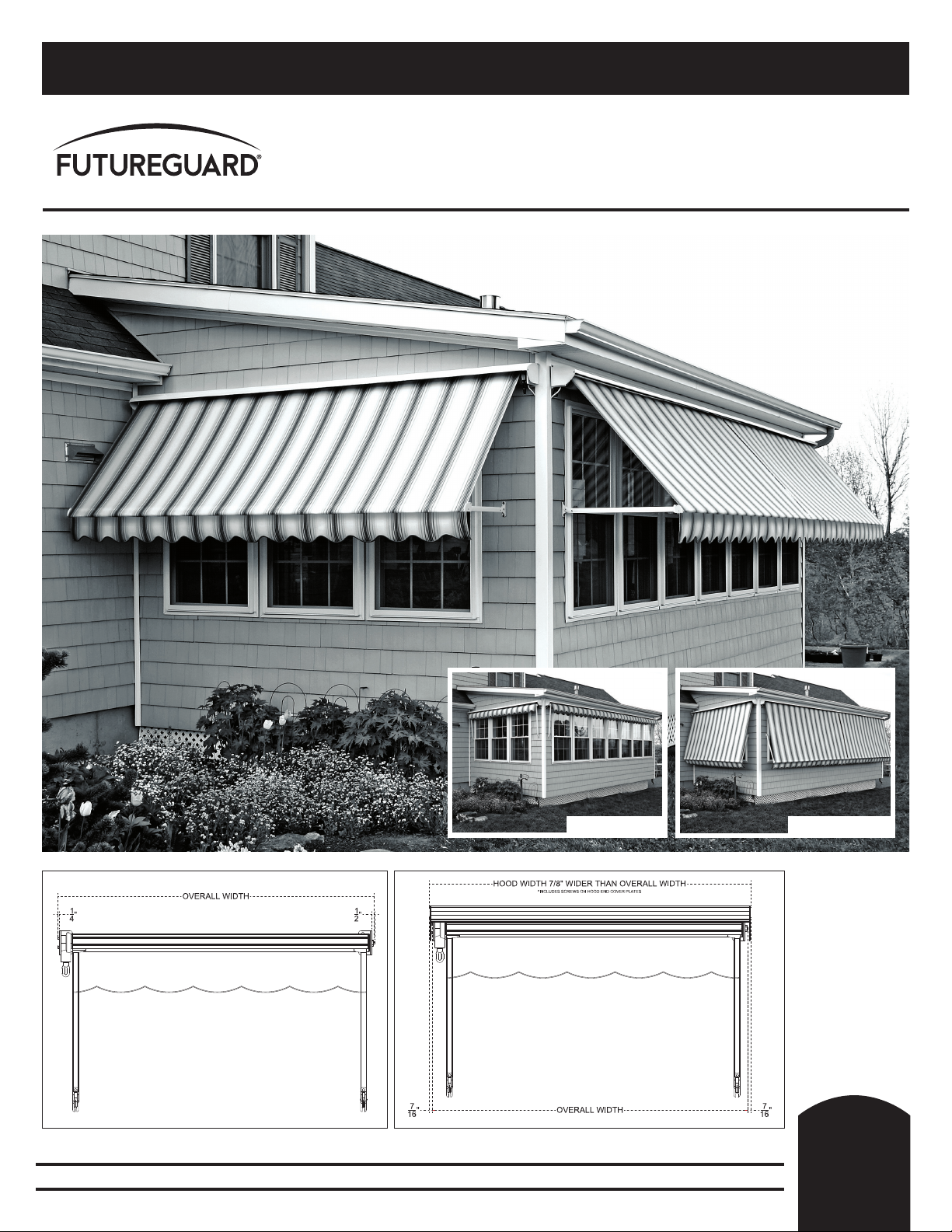
The Robusta
RETRACTABLE WINDOW AWNING
Robusta fully retracted
PROFESSIONAL • TECHNICAL • INSTALLATION • GUIDE
33
⁄16”
1”
41
⁄8”
1
⁄2”
3
⁄8”
3
⁄8”
3
⁄4”
Robusta without optional Weatherguard Hood: Robusta with optional Weatherguard Hood:
Robusta in down position
1-800-858-5818 • www.futureguard.net R
GUIDE
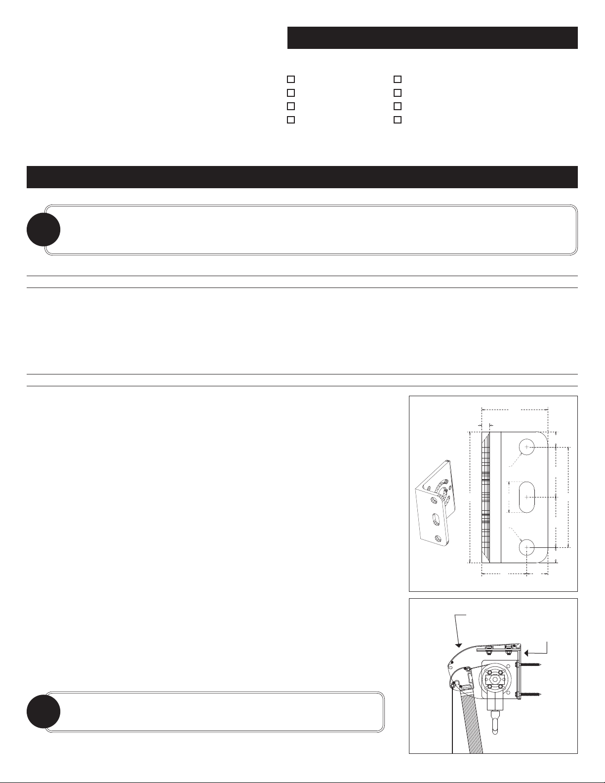
Fig. 2A
1: PREPARING THE INSTALL
Determine your awning mounting location on the wall or soffit. Lay the Robusta roller tube and bracket assembly on a clean flat surface
with the wall brackets in place. Measure the full width of the assembly including the end brackets. The bolts’ holes for securing the bracket
to the wall are 1½" in from the outside of each wall bracket. Remove the pin end wall bracket and use it as a guide to mark the wall with the
location of each end bracket based on the full width measured earlier. If mounting on the wall above a window, make sure it is located high
enough to prevent the fabric roll from rubbing on any window trim or drip edge.
2: INSTALLATION OF THE BRACKETS AND ROLLER ASSEMBLY
Remove the end bracket from the motor or gear drive and mount both brackets to the wall
or soffit with the proper fasteners. Use the top and bottom round holes in the bracket for
the fasteners. (See Fig 2A) The idler end bracket has a plastic bushing to receive the pin end
of the roller tube.
IF HOOD EQUIPPED: (See Fig 2B) If your awning was ordered the an optional
Weatherguard hood cover, install the “L” shape hood bracket behind each roller tube
end bracket and install any additionally included “L” shape hood brackets evenly
spaced in line with the two end brackets.
IF OVER 20’ WIDE: If your Robusta awning is over 20' wide it will come with either a
center roller support(s) or a split roller coupling.
IF YOU HAVE CENTER SUPPORT(S): They should be bolted to the wall inline with
the end brackets and on the seam(s) on the fabric near the center of the awning
fabric roll. Measure the seam location(s) in from the end of the awning and install
the center support(s) at that location.
IF YOU HAVE A SPLIT ROLLER COUPLING: The coupling and two mounting
brackets are to be installed in line with the end brackets at the proper location
based on each roller tube section.
Lift the roller tube and front bar assembly into place by inserting the pin end into the bushing
and swinging the motor or gear into place and securing with the bolts previously removed.
If the unit has a center coupler, be sure to align the roller tube fabric grooves on each roller
tube when inserting the square pins into the center coupling.
TOOLS NEEDED:
MOUNTING INSTRUCTIONS: Please read these instructions carefully before proceeding with assembly and installation.
before proceeding with assembly and installation
For Robusta assembly & installation, you will need:
Drill and bits
Level
Tape measure
Screw drivers
Adjustable wrench
9/16" socket and ratchet wrenches
10mm and 13mm open end wrenches
2.5mm Allen wrench
The Robusta
INSTALLATION INSTRUCTIONS
Note: This awning may be mounted directly to a wall
with optional hood and side covers, or under the soffit
without a hood and side covers. Not recommended for
installation over operating casement windows.
It is critical that the mounting lag bolts be installed into a stud or double header board. Plywood sheathing or equivalent will
not support the awning. Heavy duty toggle bolts may be used on ½" or thicker sheathing. If mounting to any surface other
than a wood framed structure, please consult with a fastener supply company for the proper fastener recommendation.
NOTE: Be sure the fabric is positioned to be rolling o the top of the roller tube.
If not, you have to rotate the assembly 180 degrees.
!
!
Fig. 2B
33
⁄16”
1”
41
⁄8”
1
⁄2”
3
⁄8”
3
⁄8”
3
⁄4”
Weatherguard hood
(side view)
33
⁄16”
1”
41
⁄8”
1
⁄2”
3
⁄8”
3
⁄8”
3
⁄4”
L-shaped
fitting
4
1
⁄
8
”
2
3
⁄
16
”
3
3
⁄
16
”
1
9
⁄
16
”
1
9
⁄
16
”
11
⁄
16
”
1”
1
1
⁄
2
”
1
⁄
2
”
1
⁄
4
”
1
⁄
2
”
1
⁄
2
”
1
⁄
2
”
TOOLS NEEDED:
Adjustable wrench
9/16" socket and ratchet wrenches
10mm and 13mm open end wrenches
2.5mm Allen wrench
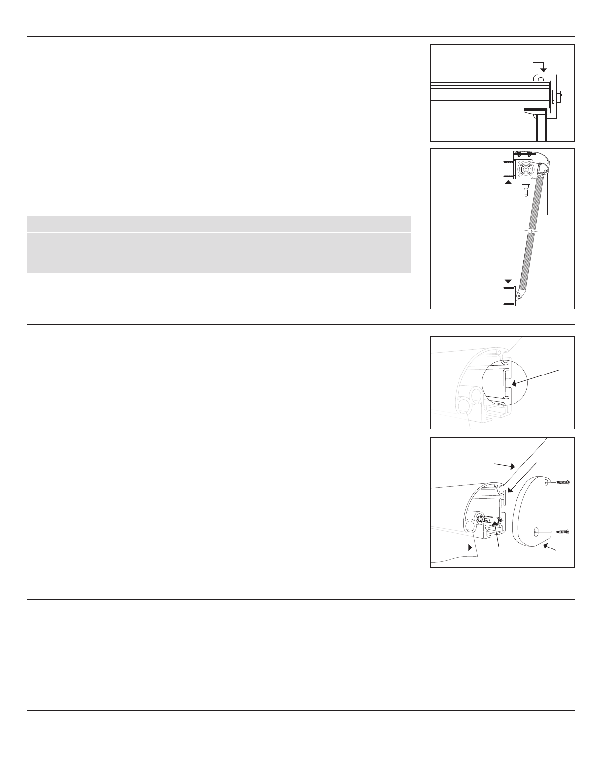
3: INSTALLATION OF ARMS
The arms are first attached to the siding or window trim below the awning and then attached
to the front bar. The outer arms will be oriented with the “L” shaped fitting at the end of the arm
facing towards the center of the awning. (See FIG 3A.) Two arm awnings should have the outside
arms located near the end of the front bar with any additional arm(s) spread evenly in along the
center of the front bar.
Use a straight edge to locate the area vertically below the front bar on the window trim or siding
at least 1" in from the end of the front bar. See the chart below to determine the distance below
the mounting bracket for the arm bracket attachment and mark the siding or trim. (See FIG 3B.)
With the arm pointing toward the ground and the “L” shaped fitting at the end of the arm facing
toward the center, install the fastener through the top hole in the arm bracket at the location
previously marked Carefully swing the arm up to 90 degrees and install the fastener in the lower
arm bracket hole making sure it is square and vertical. Repeat for all arms.
Robusta Arm Installation:
Arm size/Projection: 24 30 36 42 48 54 60
Distance from bottom of roller
tube end bracket to top hole of 181
⁄4" 241
⁄4" 301
⁄4" 361
⁄4" 421
⁄4" 481
⁄4" 541
⁄4"
arm wall mount bracket:
Distance from bottom of roller tube end bracket to top hole of arm wall mount bracket is 5 3/4" less than full projection. Arm
extrusion is cut 5" less than overall projection.
4: ATTACHING ARMS TO FRONT BAR
Attaching the front bar to the arms to the front bar is achieved by unrolling the fabric with the
front bar down to the arms which are pointed toward the ground. The arms are attached along
the back of the front bar in the shallow channel.
GEAR OPERATED AWNING: Unwind the fabric and front bar down until the front bar is about
3" below the end of the arms.
MOTOR OPERATED: See motor programing and limit setting in order to unwind the fabric
and front bar down until the front bar is about 3” below the end of the arms.
Remove one end cap from the front bar.
Remove the “T” bolts from all of the arms and slide the “T” bolts into the back of the front bar in
the shallow channel. (See FIG 4A.)
Lift and roll the front bar forward inserting each “T” bolt into the "L" fitting at the end of each arm
and thread a flange nut loosely on the each bolt.
Once the arms are attached, slide the front bar to visually align it with the roller tube as they are cut
the same size. Make sure the arms are square to the building and securely tighten each flange nut.
Carefully roll the awning up until the front bar touches the roller tube. If motorized, make any final
limit adjustment for both the opening and closing travel.
Insert the valance and fabric locks into the front bar. (See FIG 4B.) Secure and replace the front bar
end cap.
5: ATTACHING THE OPTIONAL WEATHERGUARD HOOD
Slide two “T” bolts for each wall bracket into the slots on the underside of the hood.
Place the hood onto the brackets, center and secure with the nuts.
Install the end covers with the Phillips sheet metal screws.
If your awning is gear operated the installation is complete. If you have an optional motor proceed
to the motor section for programming and limit switch setting instructions.
6: OPTIONAL MOTOR INSTRUCTIONS:
If your awning is equipped with a 3-wire RTS remote control motor, please identify which motor you have and follow the programming and
limit switch settings on the next page. If your motor has a 4-wire pigtail, please contact Futureguard for wiring and limit setting instructions.
Fig. 3A
33
⁄16”
1”
41
⁄8”
1
⁄2”
3
⁄8”
3
⁄8”
3
⁄4”
33
⁄16”
1”
41
⁄8”
1
⁄2”
3
⁄8”
3
⁄8”
3
⁄4”
L-shaped fitting
See Arm
Installation
chart at left
Fig. 3B
Fig. 4B
Awning Fabric
End Cap
Fabric
Lock
Valance
Front
Rail
Fig. 4A Slide "T" bolts
into shallow
channel

SOMFY ALTUS NON-OVERRIDE RTS REMOTE CONTROL MOTOR PROGRAMMING AND LIMIT SETTING INSTRUCTIONS
Connect the power by plugging in the motor or hard wiring. Initiate Programming On the transmitter, press and hold both the UP and DOWN simultaneously
until the awning jogs. A jog is a brief up and down or in and out motion. In PROGRAMMING MODE, the awning will move only when the UP or DOWN is held (or
momentary fashion).
Check the Direction of operation If hand-held transmitter direction is not properly programmed, Eolis/Soliris RTS sensor will not function in the manner it was
intended. Damage to motorized awning and injury may occur as a result. Check Directions Press and hold UP or DOWN. When pressing DOWN product should go
down or out. If awning does not correspond with UP or DOWN you must REVERSE the output direction. To reverse output direction, simply press & hold the (STOP)
until the awning jogs. The down button should now cause the awning to open.
Set the Upper Limit:
STEP 1: Bring the awning to desired UPPER limit stop point with the UP button. Press and hold both (STOP) and DOWN simultaneously until the awning starts to
move, then release. If the awning stops when the buttons are released, take it back to the UPPER limit and repeat. Stop the motor when desired LOWER
limit is reached. You can adjust by pressing UP or DOWN after stopping the motor.
Set the Lower Limit:
STEP 2: Press and hold both (STOP) and UP simultaneously until the awning starts to move, then release. The awning will stop at the UPPER limit that was
previously set.
Confirm Limit Settings STEP 3: Press and hold (STOP) until the awning jogs to confirm the limit settings. A jog is a brief up and down motion. In case of
problems with setting of limits during PROGRAMMING MODE, turn the power off to the motor for 2 seconds and then back on to reset the motor. Please
return to PROGRAMMING MODE to initiate programming process.
To Change the Lower Limit:
STEP 1: Press DOWN to send the awning to its current LOWER Limit.
STEP 2: Press and hold both UP and DOWN simultaneously until the awning jogs. Use the Up/Down arrows to adjust the awning to its new lower limit position
STEP 3: Press and hold (STOP) until the awning jogs, to confirm new limit.
Adjust to a new UPPER limit position:
STEP 1: Press UP to send the awning to its current Upper Limit.
STEP 2: Press and hold both UP and DOWN simultaneously until the awning jogs. Use the Up/Down arrows to adjust the awning to its new upper limit position.
STEP 3: Press and hold (STOP) until the awning jogs, to confirm new limit.
Lock in the Transmitter.
Press and hold the small programming button on the back of the transmitter with a nail. The motor will jog and now should run without having to
continuously hold the up or down button.
To add an additional transmitter/channel or sensor:
Press the PROGRAMMING button on the back of the already programmed transmitter until the motor jogs. Then, press the PROGRAMMING button on the
additional transmitter or sensor that you would like to add until the motor jogs. Test new transmitter or added sensor.
SIMU BY SOMFY MANUAL OVERRIDE RTS REMOTE CONTROL MOTOR PROGRAMMING AND LIMIT SETTING INSTRUCTIONS
Install the manual override shaft in the motor to allow manual hand crank operation.
Connect the power by plugging in the motor or hard wiring.
Initiate Programming On the transmitter, press and hold both the UP and DOWN simultaneously until the awning jogs. A jog is a brief up and down or in and out
motion. In PROGRAMMING MODE, the awning will move only when the UP or DOWN is held (or momentary fashion).
Check the Direction of operation If hand-held transmitter direction is not properly programmed, Eolis/Soliris RTS sensor will not function in the manner it was
intended. Damage to motorized awning and injury may occur as a result. Check Directions Press and hold UP or DOWN . When pressing DOWN product should go
down or out. If awning does not correspond with UP or DOWN you must REVERSE the output direction. To reverse output direction, simply press & hold the (STOP)
until the awning jogs. The down button should now cause the awning to open.
Setting the Limits:
Note the triangle arrows next to the motor limit screws. The triangle points in the direction of the roller tube rotation. If the power cord protrudes from the bottom
of the motor, the forward screw will control the DOWN and the back screw will control the UP.
STEP 1: Press the transmitter to run the motor in the selected direction.
STEP 2: If the motor stops on its own before reaching the desired stop, turn the appropriate limit screw in the positive(+) direction. Every 2 to 3 turns of the limit
adjustment screw will allow the motor to travel about 1 inch further. After every few turns of the limit adjustment screw, use the transmitter to move the
motor to the new limit position. (If the motor does not stop on its own before reaching the desired limit, go to step 4.)
STEP 3: When you are approximately at the desired limit position, use the transmitter to run the motor away from the limit 2 to 3 feet, and then back. This will
allow you to see precisely where the limit is set. Make small adjustments and repeat.
STEP 4: If the motor does not stop on its own at least 6 inches before the desired limit position, stop the motor with the transmitter. Then turn the limit
adjustment screw in the negative (-) direction. Confirm that the motor is stopped at the limit and set the limit as per step 2. If the motor is not stopped at
the limit, continue turning the limit adjustment screw (up to 120 turns may be required).
STEP 5: Set both limits at the desired UP and Down positions.
1-800-858-5818 • www.futureguard.net
Robusta Technical 03/17
Table of contents
Other Futureguard Accessories manuals


