5
III.2 Secure the hood to the ceiling
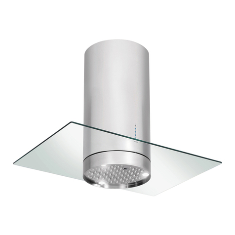
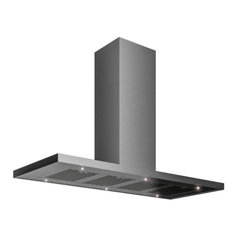
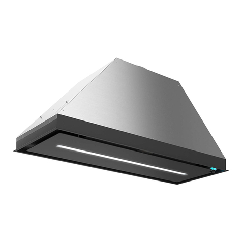
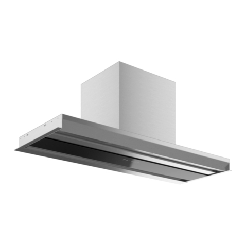
The unit (Fig. 3.2.1) is composed of the following elements:
1) Hood module
2) Telescopic chimney
3) Glasses
All fixtures are provided with the cookerhood.
To install the hood, refer to Fig.3.2.2.
Before installing the cookerhood, remove the anti-grease filters, disassemble and remove the bottom unit by
disconnecting the electrical connectors of the lights and of the display, then proceed with the disassemby of the canopy
unit, the blower unit and the telescopic chimney.
Before proceeding with the installation, place the cables inside the niche, as illustrated in Fig. 3.2.3-A.
Mounting the main structure to the ceiling
1) Secure the telescopic structure to the ceiling using the anchor bolts provided (Fig. 3.2.4) in the kit.
2) Adjust the height of the telescopic structure by turning the screws illustrated in Fig. 3.2.5.
The Canopy unit extends 376 mm past H and the minimum clearance between the appliance and the gas hob is
650mm, or between the appliance and the induction hob is 500, as illustrated in Fig. 3.1.2.
Mounting and installing the telescopic chimney
3) Mount the chimney unit and secure in place to the structure previously secured to the ceiling with the screws
as illustrated in Fig. 3.2.6.
4) Install the blower box unit inside the telescopic structure and secure it with the screws as illustrated in Fig.3.2.7.
Mounting and installing the canopy unit
5) Mount the canopy unit to the telescopic structure and secure in place with the screw fixtures to the extractor unit
as illustrated in Fig. 3.2.8.
Mounting and installing the bottom unit
6) Connect the LED indicator lights power cable from the blowe unit to the canopy unit, Fig. 3.2.8-A.
7) Connect the lighting power cable between the extractor unit and the bottom unit, Fig. 3.2.9-A.
8) Secure the bottom unit to the blower unit using the 4 screws as illustrated in Fig. 3.2.9.
Mounting and installing glass panels
9) Mount the glass panels and secure in place using the screws and washers provided (Fig. 3.2.10).
Reinstall the anti-grease filters (Fig. 3.2.11).
III.3 Electrical Connection
The electrical connection must be carried out ONLY by qualified technicians.
The electrical protection of the electrical connection upstream of the equipment must comply with the regulations in force.
Any change to the electrical installation necessary to install the hood should only be undertaken by qualified staff.
After installation, insulated parts and those carrying electricity must be protected from any possible contact.
Caution! If the electrical connection is carried out incorrectly or not meeting the regulations, it may
damage part of the appliance and the warranty will not be valid.
Warning! Before making the electrical connection, turn the main switch of the domestic system to "off".
These appliances must be earthed.
The appliance is supplied without plug and must be connected to the electrical system with a voltage of 120V and a
frequency of 60Hz.
One type of connection to the electrical network is possible:
Stable connection to the network by interposing a bipolar switch to ensure disconnection from the
network, with a contact opening distance allowing complete disconnection under the conditions of
the overvoltage category III, by the installation rules (Fig. 3.3.1.).
Earth connection (yellow-green wire) should not be interrupted.
If the power cord is damaged, it must be replaced by the manufacturer or its authorized service
center or by a qualified technician, to prevent any risk.
IV USE
This cooker hood can be installed in ducted or filtering mode.
Ducted (external evacuation, Fig. 4.1). Remove any anti-odor filters if present. Kitchen smokes are vented outside through
a flue (not provided with the hood) joined to the exhaust pipe flue connector. This pipe must not under any circumstances
be connected to cooker, boiler or burner exhaust pipes, etc. Install this flue after completing what is described in the
INSTALLATION.
The use of pipes and holes on the wall with a smaller diameter than the motor output will cause a decrease
in suction performance and an increase in the noise level.
Use as short as possible tubes and with few curves. Use pipes with smooth internal surfaces
.
3.3.1
