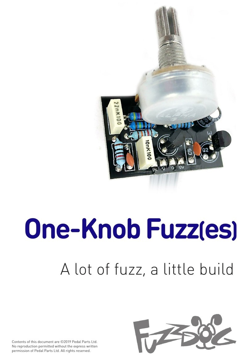
Latest version of the PCB lets you mount the pots straight onto it, saving on wiring
and eliminating the worry of how to fix the board inside the box. You can wire them
off-board if you like, just connect wires to VOLU E and FUZZ pads 1-3 instead of
sticking the pot into it.
The wires for OUT, IN, 9V and GND can be connected on either side of the board,
depending how you want to route the wiring. The pads are connected to both sides
of the PCB.
Wiring shown overleaf will disconnect the battery when you remove the jack plug
from the input, and also when a DC plug is inserted.
Snap the little metal tag off the pot to mount it flush in the box.
You UST use some kind of heat sink on the legs of the transistors
when soldering. They aren’t keen on heat. Any more than 3-4
seconds of iron and they’re toast.
Recommended assembly order:
Resistors, Caps, Transistors, Wires, Pots
As stated on the previous page, this is labelled for PNP builds.
Reverse C1 and C2 and treat -9V as +9v for NPN builds.
R4 is actually a preset variable resistor, marked ‘bias’ on the
board. ore about the importance of that overleaf.
HANG ON!!!!??! The board has two extra caps - C4 and C5? Yes. There’s
space there for optional smoothing caps for both transistors. If you find there’s too
much top-end fizz going on just put a cap in one, t’other or even both those spots.
The bigger the cap, the more frequency it’ll tame. Anything from 10pf to 150pf will
work. Have a fiddle and see what works for you. Socket them and switch around
until you have aural nirvana. Unlike you’ll need them with germaniums though.
C3 cuts a lot of the bass from the signal before the output. If you want it slightly
beefier just increase this cap. Anything up to 100n (.1u) is cool beans.
If you find you’re getting an audible ‘pop’ when engaging the circuit, just stick a 1
resistor between the “BOARD INPUT” and “BOARD GROUND” lugs on the switch.
1 2 3
C
B
E
E
B
C


