FVG Romi Start-UP User manual

Römi®Start-UP Instructions for Use
Version 08/2022
Competence in fi lms
Example

3|282|28
Contents
Introduction Page 3
Hazard and safety information Page 4
Required tools/ general assembly instructions Page 5
MiniRömi®Start-Up parts list Page 6
MiniRömi®Start-Up individual push-fit tubes Page 7
MiniRömi®Start-Up parts overview Page 8
MiniRömi®Start-Up push-fit tubes Seite 9
MiniRömi®Start-Up assembly Page 10-22
Information about the use of MiniRömi®Start-Up Page 23-24
Dismantling and disposing of MiniRömi®Start-Up Page 25-26
Warranty and liability Page 27
FVG Römi®Start-Up
(Varianten 6/8/10/12/14 m + je 2 m)
FVG Folien-Vertriebs GmbH
Ebernhahner Str. 22 | D-56428 Dernbach / Germany
Phone: +49 (0) 26 02 / 92 64 0 | Fax: +49 (0) 26 02 / 92 64 24
info@fvg-folien.de
www.fvg-folien.de
Introduction
Dear Greenhouse Friends,
Thank you for placing your trust in us by purchasing one of our high-quality
Römi®-greenhouse systems for the cultivation of plants (vegetables, herbs, fruit,
flowers).
Keep these instructions for use for later reference.
IMPORTANT!
Read the following information before you unpack and assemble the product.
• Read these instructions for use carefully and thoroughly.
• Pay particular attention to the warnings and safety instructions.
• Before you begin assembling the product, use the parts list to check that
all parts have been supplied and are undamaged.
Example

5|284|28
!
WARNINGS
• DANGER TO LIFE AND ACCIDENT RISK FOR CHILDREN AND INFANTS!
• RISK OF SUFFOCATION! Never allow children to play with the packaging material or film
unsupervised!
• RISK OF SWALLOWING and SUFFOCATION! Keep children and infants away from the
location when you are assembling the product because the consignment includes
small parts.
• CAUTION! Metal parts and metal profiles can have sharp edges so there is a
RISK OF CUTS and INJURIES! Wear protective/work gloves when opening the shipping
carton and when checking the parts against the parts list.
• WARNING! The product is not a climbing frame or an item of play equipment. Children
should be supervised at all times!
• RISK OF TIPPING and SUFFOCATION! Do not place objects on the product, use it to pull
yourself up, climb underneath it or climb into the packaging.
• WARNING! Strong sunlight can lead to the temperature inside the closed, unventilated
greenhouse rising to a level that poses a hazard to health. Ensure that there is
sufficient ventilation when people are inside and do not remain inside for too long.
• ACCIDENT RISK! Always ensure that the ladders are in a secure position.
• WARNING! Film is combustible! Do not expose it to heat sources or open flames!
SAFETY INSTRUCTIONS
• Assemble the greenhouse at a location that is sheltered from the wind (e.g. on
the lee side of a building, depending on the main wind direction).
• The greenhouse is to be used for the intended purpose only and as a stationary
installation. It must therefore be anchored to a suitable supporting surface.
• ATTENTION! Always ensure that the anchors are secured in the ground.
• CAUTION! Do NOT assemble the greenhouse in windy weather!
• CAUTION! It is dangerous to leave a semi-assembled greenhouse exposed to the
weather. In particular, the partially mounted film can provide a large surface that
functions like a sail in windy weather.
• CAUTION! It takes at least 2 people to assemble the greenhouse.
• CAUTION! RISK OF CUTS and INJURIES! Always wear protective/work gloves when
handling the product. The metal parts can have sharp edges and corners.
• Only use robust tools that are suitable for manual work.
• ATTENTION! When it is windy the greenhouse door(s) and side vents have
to be kept closed.
• ATTENTION! The greenhouse is not designed to support snow loads. Always remove
snow. Otherwise the greenhouse may collapse! Alternatively, if the greenhouse is empty,
the film can be removed during the winter.
• ATTENTION! If the film is not correctly tensioned on the frame it is possible that
rainwater will collect on the roof and exert a load on it. Remove the water pockets
from the greenhouse roof.
• Dispose of the packaging material and any remaining film safely and properly.
!
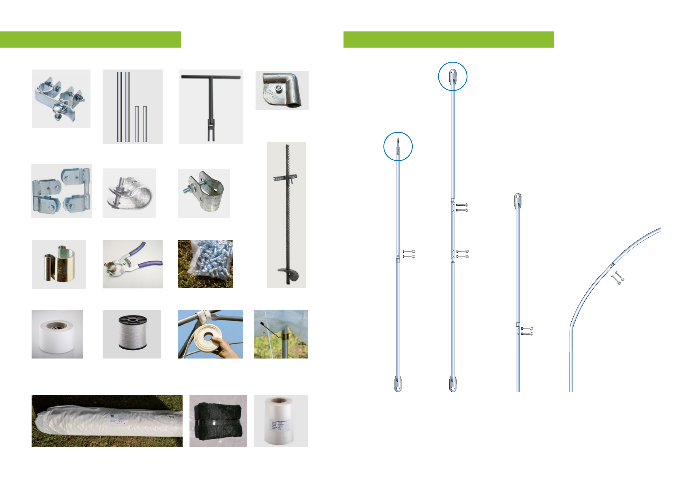
Required tools (not supplied)
• Protective/work gloves
• Sledgehammer
• Pipe wrench
• Ratchet (13mm socket) & 13mm
combination wrench
• Allen key IS5
• (Mason‘s) cord
• Carpet knife
• Scissors
• Trestle
• Spirit level
• Tape measure/folding rule
• Small wooden board
• 2-3 people for assembly
• 2 small (step)ladders
!General assembly instructions
• Read all sections of the instructions for use thoroughly before starting to
assembly the product.
• The user is responsible for obtaining any necessary planning permission or
building law approvals.
• The Römi
®
Start-Up can be set up in different positions and locations. This
involves
adapting and adjusting the individual tunnel elements to the specific
location. We cannot provide any precise measurements for that reason. Instead
,
we use approximate information or phrases such as „adjust to requirements“.
• Tunnel components that are exposed to direct sunlight can heat up and
cause burns. When assembling and using the tunnel, please avoid contact
with hot parts.
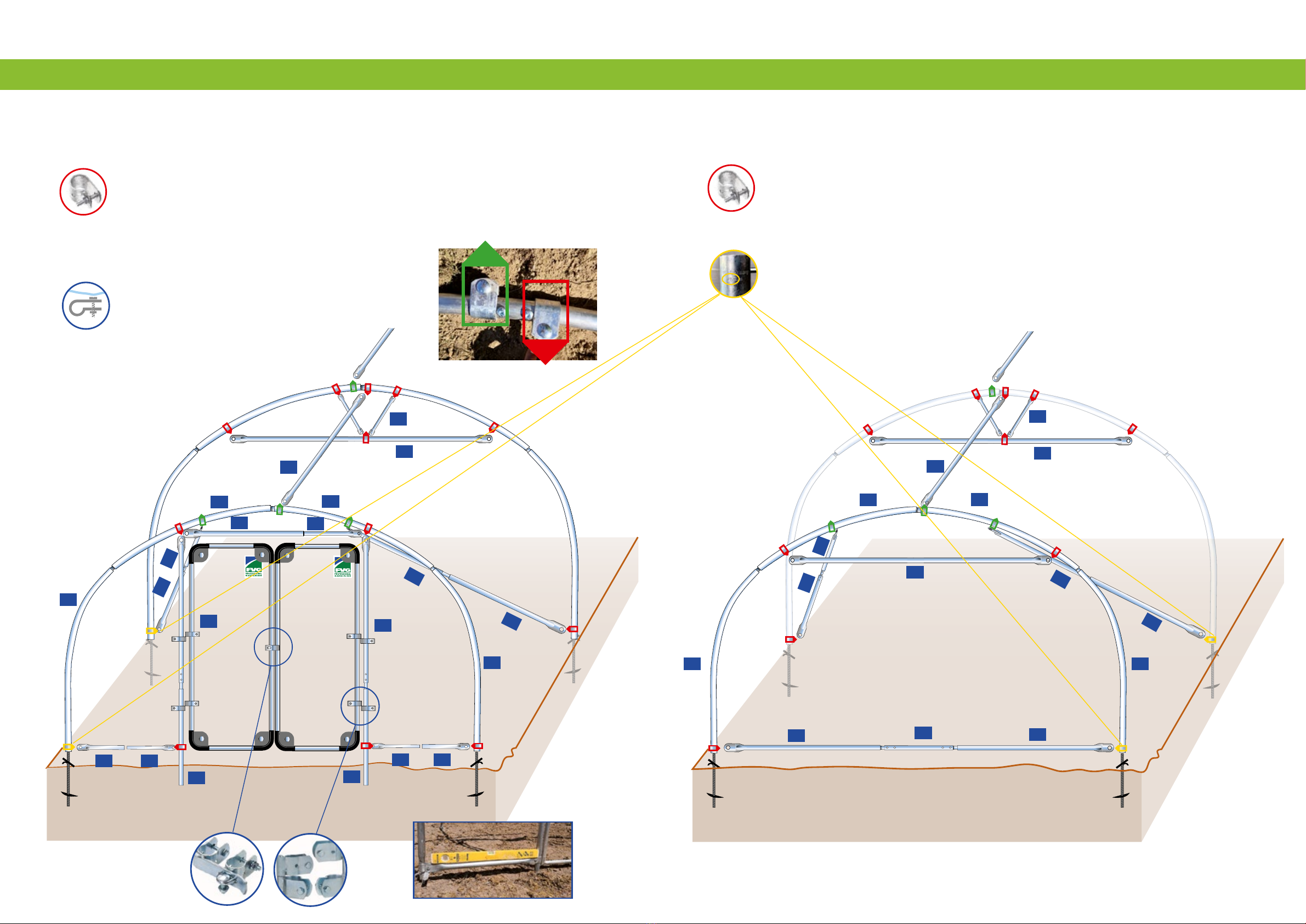
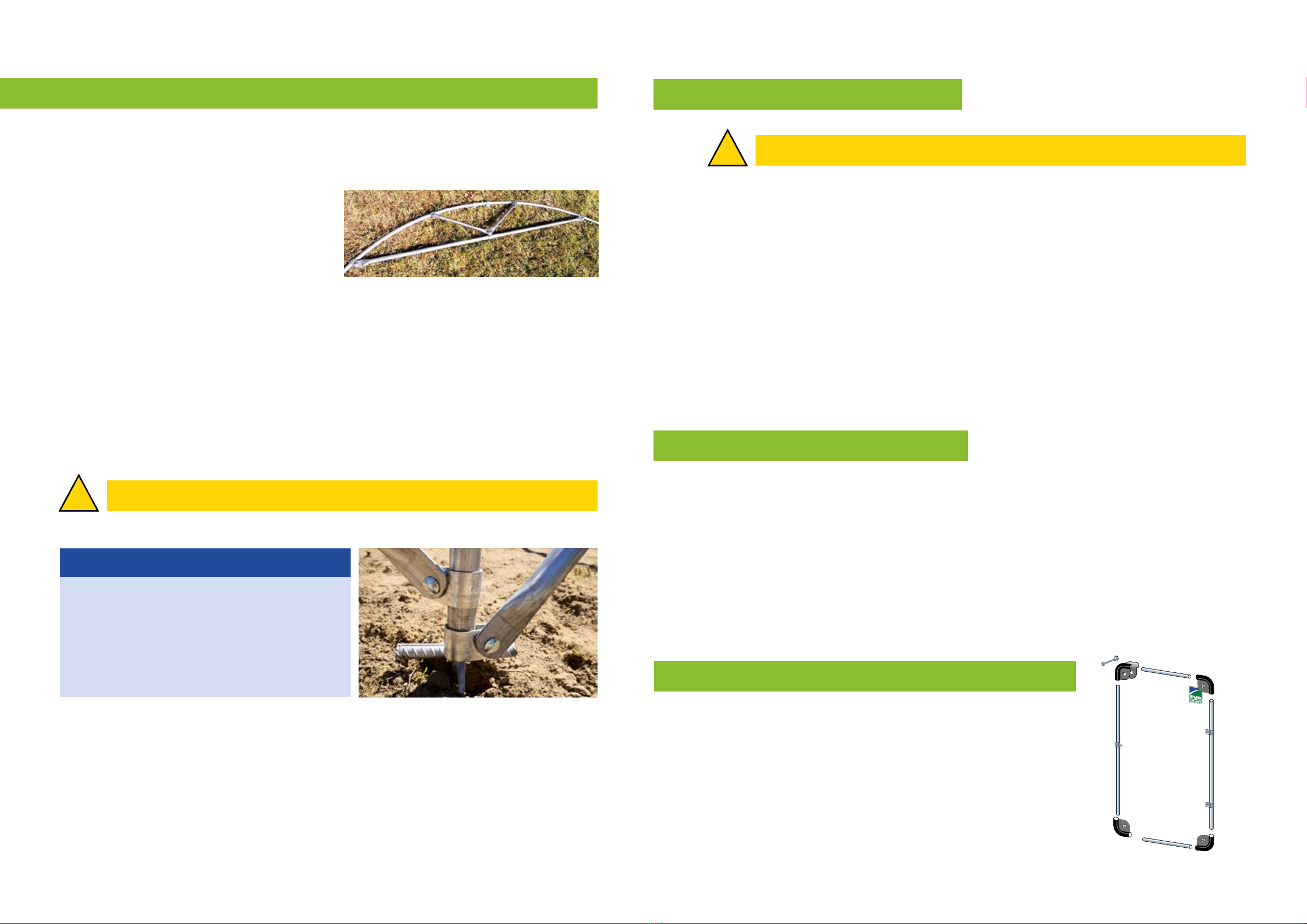
• Initially, the bolt clamps slide up and down the tubes. Therefore, always
ensure that the bolt clamps are at the correct position on the arch before
screwing them into place. Once they have been screwed into place, the bolt
clamps cannot be slid over the screw connections.
•
General care instructions are included in every roll of film. We recommend
that you read them carefully.
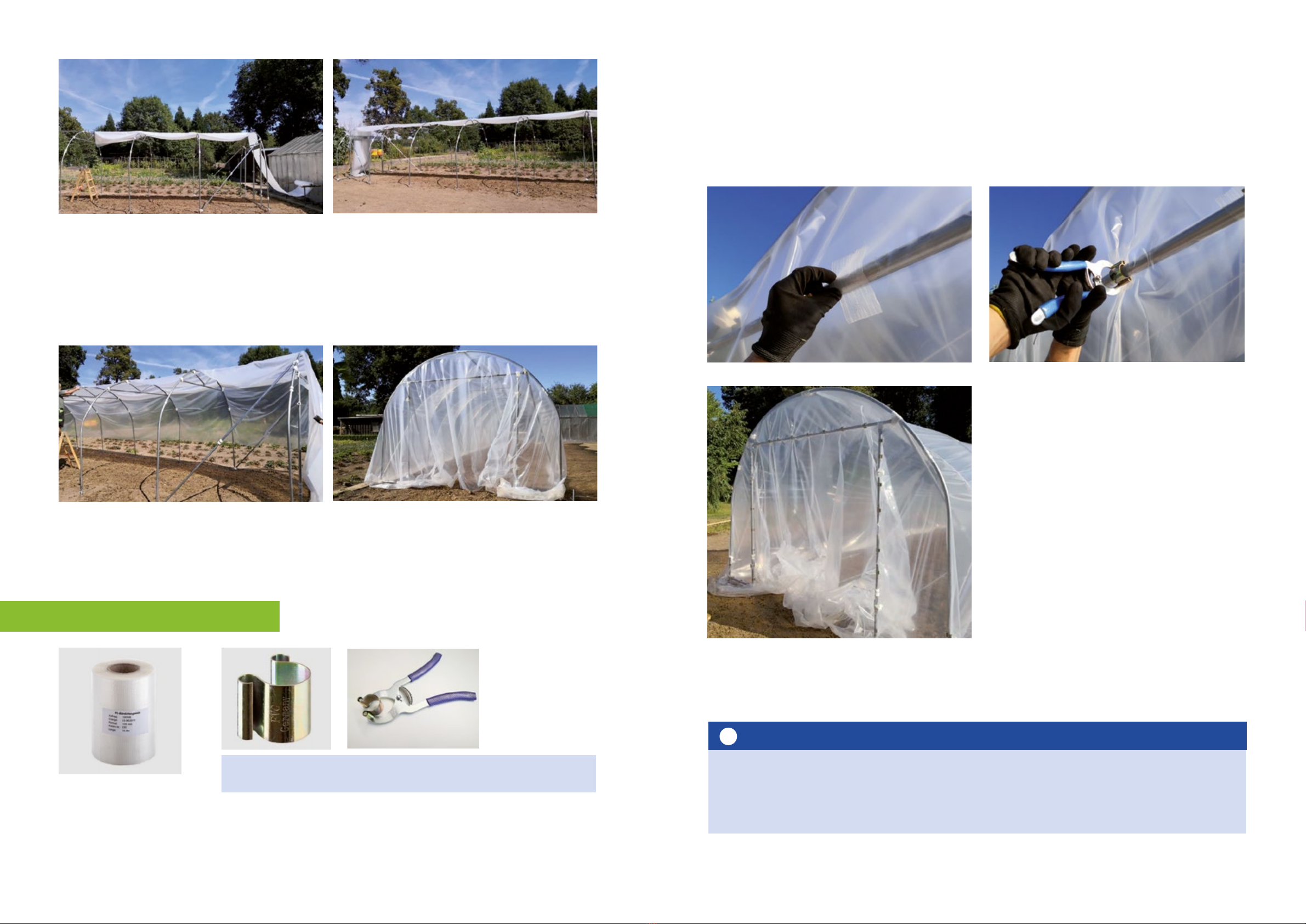
• It is impossible to assemble the film on the frame without folding it. The folds
have to be arranged so that no troughs form where water can collect.
• Don’t combine the parts for one arch with the parts for another arch. We
commend the successive assembly of the arches and that only one
package/ bundle is opened at a time.
• Don’t worry if your
MiniRömi
®
Start-Up
is initially not perfectly aligned and looks
a little crooked. These slight flaws can be remedied in the assembly process.

Römi®Start-Up individual push-fi t tubes
PART D AND D1
curved
D = 2 x 1.80 m
D1 = 2 x 1.80 m 7|28
PART A1
1.50 m
PART A2
1.00 m
PART B
1.57 m
PART E
0.50 m
PART F
0.50 m
PART I
2.00 m
PART C
0.50 m
6|28
PART G
0.50 m
PART H
0.96 m
Römi®Start-Up parts list
Parts A, B, C and D are push-fi t parts. Please read the instructions! When parts are ordered directly
note the structural modifi cations in the instructions for use.
If an additional door is used the numbers of parts stated in brackets ( ) apply.
Quantity for each standard version in the relevant length
+ 2 m
Description
Römi 6 Römi 8 Römi 10 Römi 12 Römi 14
Part A1 1.50 m, 4 x wind brace counterpart
and 1 x (2) door ridge
5 (6) 5 (6) 5 (6) 5 (6) 5 (6)
Part A2 1.00 m, door post lower section 2 (4) 2 (4) 2 (4) 2 (4) 2 (4)
Part B 1.57 m, 4 x for wind brace, 2 x (0) for
end purlin, 2 x (4) door post upper section
8 8 8 8 8
Part C 0.50 m, for end purlin 1 (0) 1 (0) 1 (0) 1 (0) 1 (0)
Part D 2 x 1.80 m / Part D1 2 x 1.80 m
for one 3.50 m arch
4 5 6 7 8 +1
Part E 0.50 m, 27 mm tube, spacer for arch/ door
post
2 (4) 2 (4) 2 (4) 2 (4) 2 (4)
Part F 0.50 m, 32 mm tube, spacer for arch/ door
post
2 (4) 2 (4) 2 (4) 2 (4) 2 (4)
Part G 0.50 m, 27 mm tube, V-strut 4 6 8 10 12 +2
Part H 0.96 m, 27 mm tube, door ridge counterpart 1 (2) 1 (2) 1 (2) 1 (2) 1 (2)
Part I 2 m, 32 mm tube, cross purlin, ridgepole 6 (5) 8 (7) 10 (9) 12 (11) 14 (13) +2
Ground anchor 8 10 12 14 16 +2
Manual soil drill adapter 1 1 1 1 1
Set of 4 corner connectors for door leaves 2 (4) 2 (4) 2 (4) 2 (4) 2 (4)
2.00 m poles, 27 mm tube for door leaves 4 (8) 4 (8) 4 (8) 4 (8) 4 (8)
1.00 m poles, 27 mm tube for door leaves 4 (8) 4 (8) 4 (8) 4 (8) 4 (8)
Bolt clamp 25 mm 4 4 4 4 4
Bolt clamp 32 mm 32 (36) 39 (43) 46 (50) 53 (57) 60 (64) +7
Rounded head screw 40 46 52 58 64 +6
Door hinge set 1 (2) 1 (2) 1 (2) 1 (2) 1 (2)
Door bolt 1 (2) 1 (2) 1 (2) 1 (2) 1 (2)
Foam adhesive tape 1 1 1 2 2
Greenhouse fi lm/ roll 1 1 1 1 1 ≙
Omega-shaped clip 27mm 100 100 100 100 100
Omega-shaped clip 32 mm 100 100 100 100 100
Omega-shaped clip pliers 1 1 1 1 1
Roll of protective fi lm 1 1 1 1 1
Premium-Poly-Patch® adhesive repair tape 1 1 1 1 1
Ventilation clips 4 6 8 10 12 +2
Shading net, dark green
1 1 1 1 1 ≙
Tension rope, 100 m reel 1 1 1 2 2 ≙
Instructions for use 1 1 1 1 1

9|288|28
Römi®Start-Up parts overview
Ground
anchor
32 mm bolt clamps
Rounded head
screws
Door hinge
Door bolt
Foam tape
Roll of protective
fi l m
Polyester rope
27 mm & 32 mm
omega-shaped clip
(see engraving)
Omega-
shaped clip
pliers
Greenhouse film
Corner connector
for door
4 door poles
Ventilation clips
Premium Poly Patch,
special greenhouse film
adhesive tape
(for repairs)
Shading net
25 mm bolt clamps
(see engraving)
Manual soil drill
adapter
Römi®Start-Up push-fi t tubes
WIND BRACE
Part A1 + Part B
3.00 m
Important: Turn pole
A1 90°
DOOR POST
Part B + Part A2
2.50 m
Don’t screw these
parts together yet.
ARCH
2 x Part D and 2 x Part D1
Connection sequence:
Part D1 + Part D + Part D + Part D1
END PURLIN
2 x Part B + Part C
3.50 m

11|2810|28
Römi®Start-Up assembly
First check that the shipment carton contains all the necessary parts by check-
ing them against the parts list. Ensure that the materials are complete and
undamaged to avoid problems during the assembly process.
Step 1
Take the time to find a wind-protected location where
you can assemble your Römi®Start-Up. Remember that
shade can have a negative impact on yield.
Determine the main wind direction. We recommend
that the tunnel is positioned with the side facing the
main wind direction so that the wind can flow over
the top. In some locations it can be advantageous
to choose a different position, or the recommended
position may not be possible.
General instructions on wind stabilization:
As the first step we recommend setting up a windbreak net in the main wind direction
to reduce the speed of the wind hitting the tunnel. The height of the windbreak net
should correspond to the height of the straight wall (at least 1.0 m to 1.5m). The wind-
break net should be wind-permeable and can be installed approx. 10-15cm above
the ground. Please ensure that the windbreak is securely anchored in the ground to
prevent the posts/anchors becoming loose in a storm.
If you do not erect your tunnel with the side wall facing the main wind direction as
recommended or intend to erect it at a location with permanent wind exposure, you
can take additional measures to improve stability.
- Bury the film on the sides of the tunnel – Caution: this impairs tunnel ventilation
- Incorporate additional metal struts, wind brace poles or duct tape
- Fix the first & last tunnel arches in place with tensioned rope and additional
ground anchors
For further information and queries contact us at +49 (0) 2602 9264-0
or inf[email protected].
!Important notice:
Please do not place the tunnel on an exposed area because the wind will hit the
tunnel at full speed. We recommend that a wind break is used to protect the tunnel
against wind damage.
Check the condition of the ground at the envisaged assembly location. It
must provide the ground anchors with sufficient stability. Otherwise, it cannot
be guaranteed that the Römi®Start-Up will stand firmly.
Ideally, the ground should have a 1 to 2% gradient at the assembly location to
ensure that rainwater drains off. A steeper gradient can impede secure stand
and stability. You can also create a drain on the long side of the tunnel to
divert water away.
To ensure that all anchors are in a straight line, we recommend
using (mason’s) cord between the first and last anchors and
then position the remaining anchors along the cord. You can
achieve the perfect distance if you use a 2m ridgepole (part I)
and a 32mm bolt clamp on the left and right. When the anchor
is in place, the pole with the bolt clamps should fit onto the
inserted anchor (see photo). To insert the anchors place the soil
drill adapter on top of each anchor and twist them individual-
ly into place. Check the distance between them with the 2m
ridgepole and the affixed bolt clamps after putting each an-
chor into place. The anchors on the 2nd side (opposite) are at a right angle and
at a distance of 3.5m (= tunnel width) to the anchors on the first side (see photo).
Please note that with these dimensions the tunnel is slightly longer than originally
stated because the pole including bolt clamp is >2.00m and the arch spacing is
stated as 2m.
When screwing the anchors into place, ensure that
the soil conditions provide the necessary secure hold.
Loose soil or backfill are not suitable for anchoring
purposes. The anchors must always be inserted deep
enough into the soil and be level in height. Always
check that the anchors are firmly in place and secure!
Twist in the ground anchors
Step 2
Soil drill adapter
with ground
anchor
Part I, 2.00 m, bolt clamp 32mm on right and left side
*Spacing between the ele-
ments is >2m due to the bolt
clamps on the left and right.
WARNINGS
!
RISK of CUTS and INJURIES! Always wear protective/work gloves when handling
the product. The metal parts can have sharp edges and corners.
3.5 m
The sketch shows
a 3.5m x 10m
tunnel
2 m*
Preparation for tunnel assembly

I
13|2812|28
I
B
F
B
A1
D1
D1
D
D
A2 A2
F E E
A1
I
I
B
BA1
BC
I
G
B
G
D1D1
D
D
B
A1
H
A1
B
Römi®Start-Up
The flat side of the bolt clamps
should always face outwards (to the
film). The bolt is on the side facing
away from the film.
Arch with door and wind brace
Centre arch
• Same as 2nd and penultimate arch, except without bolt clamps for wind brace
Arch 1 = (with door) = 7 bolt clamps
Arch 2 = 8 bolt clamps
Arch 3 and subsequent/centre arches until penultimate arch
= 6 bolt clamps
First thread on the bolt clamps
then connect the poles!
End arch, Römi®Start-Up with purlin version
For 2-door versions continue as described on page 12.
End arch of 1-door version = 7 bolt clamps
Penultimate arch = 8 bolt clamps
First thread on the bolt clamps then connect the poles!
Note:
Use a 25 mm bolt clamp at the tapered section of the arch
(see engraving)

14|28 15|28
!
1 m
2 m
2 m
1 m
Assemble the arches and affi x the bolt clamps in place
Step 3
• First open just one bundle of arch parts because the individual parts were bent
together. For that reason, only these parts can be connected to form a
straight arch. Do not open other bundles or mix arch parts from different
bundles because they may be twisted or S-shaped when connected.
• Arrange the parts (2x part D1 + 2x part
D + part I + 2x part G) on the floor in the
arch configuration.
• Now thread on the correct number of
bolt clamps. Ensure that the bolt clamps
are facing in the right direction. (See drawing on page 12).
• The bolt clamps should always have the flat side facing outwards (to the film).
The screw thread faces away from the film.
• When the correct number of bolt clamps have been threaded on in the right
order, you can screw together the parts of the arches (D parts), the cross purlin
(part H and B), the connecting and the V-strut (G parts). Do not com
pletely
tighten the screws initially. When you have finished the alignment (step 6)
you can tighten them securely.
Place the arches on the vertical pins of the ground anchors. If you get the im-
pression that one of the arches has twisted or it looks S-shaped, you can swap
the parts D of an arch for another arch.
• On the last arch affix the upper end purlins (part I) onto the upper part of the arch
and the lower end purlins (part C + 2 x part B) onto the lower end of the arch.
• Now connect the arches lengthways by affixing one ridgepole (part I) to the top
bolt clamps at the centre and highest point of the arches.
Step 4
Note:
The flat end of the purlin is mounted on
the flat side of the bolt clamp.
Remember: fl at to fl at.
The screw thread faces away from the fi lm.
WARNING!
ACCIDENT RISK! Always ensure that the ladders are in a secure position.
!
Example
A wind brace (part A1 and part B) is attached on each side between the first
and second arch, and the penultimate and last arch. To attach the wind brace
use the bolt clamps on part D (upper part of the arch) on the first (or last) arch
and the lower bolt clamps on part D1 (lower part of the arch) on the second (or
penultimate) arch. A 25 mm bolt clamp is used on the tapered part of the arch.
Ensure that the wind brace pole is affixed to the anchor shaft of the following
arch (second and third/ third last and penultimate arch) so that the forces are
conveyed directly to the anchor.
• When you have assembled the arches (including V-strut), the wind brace
and two end purlins you can make the final adjustments to the individual
parts by moving the bolt clamps along the arches slightly.
• When everything is aligned, you can tighten all the screws. Use the ratchet
and the 13mm socket. Then check all the screws to ensure that they are firmly
in place.
Mounting the wind brace
Adjustment and tightening
Step 6
Step 7
WARNING!
The wind brace is essential to the stability of the greenhouse. If it is mounted incorrectly
or not mounted, there is a risk of serious damage and injury!
Door frame and door system assembly
Connect the corners, the 1 m and the 2 m poles for
door leaves, as shown in the parts list, to build the door
frame.
Mount the company plaque where it is visible on the
2m outside of the film after assembly in case of later
inquiries or warranty claims. Tighten the screws so that
the tubes are stable. If necessary, the door can be re-
duced in size/ adapted by sawing/ angle grinding the
tube pairs to the required length.
Step 5

17|2816|28
!
Schritt 7
• Put the door ridge (A1/H) in the space between the
bolt clamps on the first arch (see p. 12) and, at the
same time, place the flat side of doorpost Part B on
the outside of the bolt clamp, then lightly tighten the
screw. Hold the door against the frame, remembering
to leave space for the hinges and lock. Use a spirit level
on the door ridge and door post (part B) to determine
the final right-angle position. Then hold the door post
part A2 (making sure the push-fit system overlaps and
the holes on B/A2 match) in the correct position for part
A2 and determine the correct height. Now hammer Part A2 into the ground
with a piece of wood between the part and the hammer to protect it (see
photo).
• Thread one bolt clamp onto each part A2 (flat side facing outwards; screw
facing the arch). Two door hinges also have to be threaded onto the two posts
(part A2). 1 hinge is affixed to Part B later on.
• Detach the hanging part B from the bolt clamp briefly (after determining the
bolt clamp and part A1/H’s position) and insert it onto A2 (aligning the holes).
Screw the flat side of part B on the bolt clamp onto the door ridge (in the
space between the bolt clamps).
• Now the height of the hinges and lock can be adjusted, and the relevant parts
can be attached to the door leaves/posts. The two spacers (push-fit system
comprising part E + part F) are mounted on the lower end of the arch and the
door posts.
Put the door on the hinges to test it before you tighten the screws.
Door system
Tip:
Twist the door hinge a little outwards so that the door will open fully
later on.
CAUTION! This assembly makes it impossible to open the door inwards.
Before you mount the film cover all sharp-edged elements of the arches, ridge-
poles, wind brace and door, as well as screws, with the supplied adhesive foam to
prevent damage to the film.
Preparing and mounting the film
• Only mount the film in dry weather with no wind.
• Place the film roll on two mounting blocks so that it can be easily unrolled.
Important:
Ensure that the film cut is facing up so that you can unfold the film later.
Step 8
WARNING!
RISK OF CUTS and INJURIES! Always wear protective / work gloves when handling the pro-
duct. The metal parts can have sharp edges and corners.
ACCIDENT RISK! Always ensure that the ladders are in a secure position.
CAUTION! It is dangerous to leave a semi-assembled greenhouse exposed to the weather.
In particular, the partially mounted film can provide a large surface that functions like a
sail in windy weather.

19|2818|28
Affi xing the fi lm
Step 9
Pull the film carefully over the top of the frame from one end to the other. Then
carefully start to extend it over the sides, one side first, then the other. Ensure
that no folds are created to prevent tears in the film.
Example
Use the supplied pliers to affix the omega-shaped
clips.
To prevent mechanical damage only use the supplied omega-shaped clips. The
omega-shaped clips may not be placed directly onto the greenhouse film. Cut
a piece of the protection film off the roll (double the clip width) and place it
under each clip before affixing it in place.
Tension the film on one side first, then
the other. First affix the clips to the
front, then to the back, in each case
on the lower purlins (27 mm + 32
mm omega-shaped clip), the door
posts (32 mm omega-shaped clip)
and the door ridge (27 mm + 32 mm
omega-shaped clip). Optionally, the
film can be clipped to the back of
the end purlin on the tunnel arches.
Whichever option you choose, make
sure that the clips on the front and
back are at the same height. Excess
film can initially be turned inwards
and cut off afterwards if necessary.
! Important
The film must be taut when the clips have been affixed!
Only use max. 2 layers of greenhouse film under the clips, otherwise the
omega-shaped clips can overstretch and tear!
Example

21|2820|28
!
3.
Repeat this process all the way down the tunnel so that the ropes cross on
the ridge. The rope has to be tensioned so that the film is taut and cannot
flap! After tensioning, knot the rope on the last anchor.
!Important information >6 m length
Cut the rope at some of the junctions after knotting it to an anchor, then knot
it to the anchor again and carry on. This ensures that if the rope snaps in one
section, tension is only lost on part of the tunnel.
General information:
Surplus, protruding film has to be turned inwards.
1. Knot the rope on the first
anchor.
2. Unwind the rope and throw
it over the tunnel to the diago-
nally opposite anchor.
Please only throw rope that
you have unrolled, not the
reel! Risk of injury!
Tensioning with tension rope
Step 10 Schritt 11
Place the film cut-out of the door and the assembled frame (see step 7) on a
level surface and clip the film to the door frame with the 27 mm omega-shaped
clips. (Make sure the film is taut). Then cut off the surplus film and hang the door
on the hinges.
Always place pieces of protective film underneath!
Fertigstellen der Tür mit Folie
The film to cover the door is cut out using a carpet knife between the door post
and the top door ridge. Don’t leave too much film protruding at the hinges and
ensure that it isn’t too taut.
VORSICHT!
RISK of CUTS and INJURIES! Always wear protective/work gloves when handling the pro-
duct.
Affix the door bolt to the door at
the required height before co-
vering the door with film. Ensure
that there is some slack at the
hinge and bolt (not too much
overhang). Drape it to the side of
the bolt loop or make a cut-out.
Example

14 23|2822|28
Accessories
Shading net
Hang the shading net over the tunnel and affix it with the tension rope (in the
same way that you affixed the greenhouse film) to protect your plants from
intensive UV rays.
Premium-Poly-Patch®-adhesive repair tape
If the film gets torn, you can repair it very easily by applying a piece of our
adhesive repair tape to the outside of the film. Make sure you clean the areas
where the tape will be applied beforehand.
Ventilation clips
Affix the ventilation clips as shown in the parts list to the centre arch. To ventilate
your MiniRömi®Start-Up twist the ventilation clip outwards and lay the film over it,
or use the clips as hooks on the inside of the tunnel.
Example
Information about the use of Römi®Start-Up
• For efficient ventilation of the greenhouse you can gather up the film on
the sides. It is important that you gather it properly and don’t create any
folds in the film.
• When using manual side ventilation ensure that no water pockets can
form and check the tension of the ropes. Do not use side ventilation in
windy weather.
• PE film is sensitive to temperature fluctuation. Regularly check the taut-
ness of the film and re-tension it again if necessary. If the film is too slack it
can cause buffeting damage and if it is too taut, it can cause abrasion or
scratch damage. Rule of thumb: at a temperature of 15-20 °C you should
be able to fit one finger, but no more, between the arch and film (in the
roof area).
• To optimise yield it is necessary to clean dirt off the film to prevent unwan-
ted shade. Normally, the film is cleaned by regular rainfall and additional
cleaning is not necessary. If the film gets very dirty you can add a slightly
alkaline cleaning agent to the cleaning water, but don’t use chemicals.
Apply the cleaning water with a soft cloth or sponge. If the film is very dirty,
repeat several times. Abrasive cleaning methods (e.g. scrubbing) and the
use of hard brushes are not recommended because this can damage
the film.
• At the end of the 4-year UV warranty we recommend replacing the film
before it becomes too hard and brittle.
• To prevent the open door from slamming, open it as far as the arch and
then place a sack or something similar in front of it. You can also tie the
door to the ground anchor hook on the first arch with the supplied tension
rope.

25|2824|28
HAZARD AND SAFETY INFORMATION
• CAUTION! If windy weather is forecast, or you live in an area where windy weather
prevails, close the greenhouse doors and keep them bolted. In the event of extreme
wind speeds we recommend removing the film to protect the tunnel frame from storm
damage. Please note that your plants may be damaged.
• DANGER! Check that the ground anchors are firmly in place at regular intervals, as well
as before and after stormy weather. Otherwise the greenhouse could become
unstab le. Check the side ventilation before and after stormy weather.
• ATTENTION! Check that the tension ropes are correctly tensioned at regular intervals,
as well as before and after stormy weather. Loose ropes have to be tensioned
again. Damaged ropes should be replaced.
• CAUTION! Strong sunlight can lead to the temperature inside the closed, unventilated
greenhouse rising to a level that poses a hazard to health. Ensure that there is
sufficient ventilation when people are inside and do not remain inside for too long.
• ATTENTION! The greenhouse is not designed to support snow loads. Always remove
snow. Otherwise the greenhouse may COLLAPSE! After removing snow ensure that the
tension ropes are correctly tensioned. Loose ropes have to be tensioned again.
Damaged ropes should be replaced. If the tunnel is empty over winter you can remove
the film to prevent damage to the tunnel frame (snow, storm, …).
• ATTENTION! Water pockets can form on the roof of the greenhouse causing external
loads. Remove the water pockets from the greenhouse roof.
• WARNING! Film is combustible! Do not expose it to heat sources or open flames!
• CAUTION! Tears in the film and other damage impair the greenhouse’s stability and
they provide additional surfaces which can be affected by wind loads. Always repair
tears immediately with FVG repair tape.
!
Dismantling and disposing of MiniRömi®Start-Up
!
HAZARD AND SAFETY INFORMATION
Please refer to the hazard and safety information on page 4.
All Römi parts are recyclable. The high quality and purity of the film makes it a
coveted recycling material.
Basically, the greenhouse is dismantled in the reverse order of assembly.
If there is something you would like to know about the parts, consult the sections
“MiniRömi®Start-Up parts list”, “MiniRömi®Start-Up individual push-fit tubes” and
“MiniRömi®Start-Up assembly” of this instruction manual.
Dismantling MiniRömi®Start-Up
Step 1 Preparation
This high-quality film has to be brushed clean in order for it to be recycled. This is
easiest to do when the film is still mounted on the tunnel.
Step 2 Door
Lift the door off the hinges and remove the omega-shaped clips of the door with
the supplied pliers. Then remove the film.
Step 3 Tension ropes and omega-shaped clips
• Loosen and remove the tension ropes.
• Then loosen and remove the omega-shaped clips with the supplied pliers.
Step 4 Film
Fold up the film on the long sides up to top of the arch.Now the film can be rolled
lengthways along the ridgepoles. Remove the rolled together film from the frame
at the end of the tunnel.

27|2826|28
Step 5 Foam tape
Remove all foam adhesive tape from the arches, ridgepoles, wind brace and
door, as well as from all the screws.
Step 6 Wind brace, ridgepoles & arch elements
Loosen all the screws but don’t remove them yet. Start removing the screws sec-
tion by section, but only when you are ready to dismantle the individual elements.
Check that the arch elements are still correctly positioned on the ground an-
chors. Otherwise the other arches might fall over when you continue dismantling
the frame.
Start to remove the wind brace between the first and second arch, and the
penultimate and last arch by removing the screws that you have already loo-
sened.
The ridgepole that is inserted between the first and second, and the penultimate
and last arch, can now be removed. Here, too, remove the previously loosened
screws from the holes. Since the tunnel is now unstable, you will need two people
to hold the arches.
Place the dismantled arch elements flat on the floor to take them apart in the
next step. Loosen and remove all the screws and pull the arch parts apart. Follow
the same procedure with the ridgepoles and the wind brace poles.
Step 7 Ground anchor
In the last dismantling step you remove the ground anchors. Rock the anchors
from side to side or knock them sideways with a hammer to loosen them. Any
ground anchors that are stuck will have to be dug out.
Step 8 Disposal / recycling
Take all the parts of your Römi®to your local recycling plant.
We refer to our General Terms and Conditions for information about warranty.
Please remember that the warranty is subject to the product being used for
the intended purpose and in accordance with the written instructions for use.
The warranty does not cover normal wear and tear. It also does not cover
damage, defects or wear caused by incorrect assembly, incorrect use, poor
maintenance and care, misuse, unauthorised modification or use in adverse
weather conditions.
FVG accepts no liability for damages caused by incorrect assembly or poor
care. These instructions for use have been compiled to the best of our knowl-
edge and belief. All the necessary safety precautions to be taken during as-
sembly in order to avoid causing damage to the material or injuries are stipu-
lated. We therefore cannot accept liability if, despite meticulous care in the
preparation of these instructions, they are misinterpreted by the reader with the
result of damage being caused.
Modifications to the product are not permitted and may impair the safe and
efficient use of the product. The warranty does not cover damage caused in
connection with a modification to the product. FVG accepts no liability for
damage incurred in connection with a modification to the product.
You can contact us at any time on +49 (0) 2602 92640 if you have any questions,
suggestions or feedback.
Further information on the care of the greenhouse film and the tunnel, as well
as assembly videos and accessories can be found at www.fvg-folien.de.
Enjoy using your FVG Römi®Start-Up!
Warranty and liability

www.fvg-folien.de
FVG Folien-Vertriebs GmbH
Ebernhahner Str. 22 | D-56428 Dernbach / Germany
Phone: +49 (0) 26 02 / 92 64 0 | Fax: +49 (0) 26 02 / 92 64 24
info@fvg-folien.de
Excellent technical competence and individual solutions
Regular adaptation of products to market
requirements
Fast deliveries of standard range products
International shipments possible
International expertise
Close collaboration with institutes and universities
Laboratory
Blow fi lm extrusion
Production
For further information about products contact:
Competence in fi lms
Table of contents
Other FVG Greenhouse Kit manuals
Popular Greenhouse Kit manuals by other brands

OLT
OLT Garden in a Box with Greenhouse Cover Assembly manual

GrowSpan
GrowSpan 113463H manual

Halls Greenhouses
Halls Greenhouses Altan Halls Wall Garden 42 manual

Janssens
Janssens HELIOS SL Mounting instructions

Gazebo penguin
Gazebo penguin W1608-32 Assembly instructions

ACF Greenhouses
ACF Greenhouses Grow More GM8 Assembly instructions