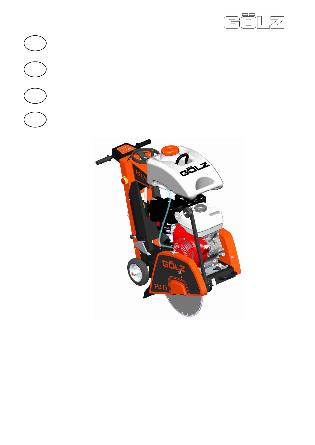
GÖLZ FS175 Guide

FS175
- 1-
5007287-01
BA-DE-GB-FR-NL
®
Original-Bedienungsanleitung und Ersatzteilliste
Fugenschneider
Original operating instruction and spare parts list
Floor saw
Originale du mode d’emploi et liste des pièces de rechange
Scie de sol
Origineel Gebruiksaanwijzing en Reservedelenlijst
Vloerenzaagmachine
ZN der Bedienungsanleitung: 5007287-01
Erstellt am: 07 / 2016
Erstellt von: Sabrina Linden
Datei: K:\KDV\5007xxx\5007287-Bedienungsanleitung\
5007287-01-Bedienungsanleitung-DE-GB-FR-NL.doc
GÖLZ®GmbH
Dommersbach 51
D-53940 Hellenthal
Telefon: +49 (0) 2482 12 200 / Telefax: +49 (0) 2482 12 222
E-Mail: info@goelz.de / Internet: www.goelz.de
GB
DE
FR
NL

FS175
- 2-
5007287-01
BA-DE-GB-FR-NL
®
Alle Rechte nach DIN ISO 16016 vorbehalten.
Kein Teil dieses Dokuments (Bedienungs-
anleitung und Ersatzteilliste) darf ohne vorherige
schriftliche Genehmigung durch die
GÖLZ®GmbH
Dommersbach 51
D-53940 Hellenthal
reproduziert, angepasst, gesendet, übertragen,
auf Datenträger gespeichert oder in eine andere
Sprache übersetzt werden.
Garantie
Wir behalten uns vor, die in diesem Dokument
(Bedienungsanleitung und Ersatzteilliste) ent-
haltenden Informationen jeder Zeit und ohne vor-
herige Mitteilung zu ändern.
GÖLZ® übernimmt keinerlei Gewährleistung für
diese Unterlagen.
GÖLZ® übernimmt ferner keine Haftung für Fehler
in dem vorliegenden Dokument Bedienungsanlei-
tung und Ersatzteilliste) oder für Neben- und
Folgeschäden in Zusammenhang mit der Liefer-
ung, Leistung oder Anwendung des Materials.
Onder voorbehoud van alle rechten volgens DIN ISO
16016.
Geen enkel deel van dit document
(gebruiksaanwijzing en reservedelenlijst) mag zonder
voorafgaande schriftelijke goedkeuring van
GÖLZ®GmbH
Dommersbach 51
D-53940 Hellenthal
gereproduceerd, aangepast, verzonden,
overgedragen, op gegevensdragers opgeslaan of in
een andere taal vertaald worden.
Garantie
Wij behouden ons het recht voor om de informatie die
u terugvindt in dit document (gebruiksaanwijzing en
reservedelenlijst) ten all tijde en zonder voorafgaande
mededeling te wijzigen.
GÖLZ®verleent geen enkele garantie voor deze
documentatie.
Voorts neemt GÖLZ®geen enkel aansprakelijkheid
op zich voor fouten in onderhavig document
(gebruiksaanwijzing en reservedelenlijst) noch voor
indirecte of gevolgschade in verband met de levering,
prestatie of het gebruik van het materiaal.
All rights reserved according to DIN ISO 16016.
No part of this document (instruction manual and
spare parts list) may be reproduced, adapted,
transmitted, transcribed, stored on a data medium
or be translated into another language without
prior written approval of
GÖLZ®GmbH
Dommersbach 51
D-53940 Hellenthal
Guarantee
We reserve the right to amend any information
included in this document (manual instruction and
spare parts list) at any time and without prior
notice.
GÖLZ® assumes no warranty for these
documents.
GÖLZ® shall not be liable for errors in this
document (manual instruction and spare parts list)
or for any collateral or consequential damage in
connection with shipment, performance or use of
the material.
Tous droits réservés selon DIN ISO 16016.
Toute reproduction ou traduction complète ou partielle
du présent document (Notice d’utilisation et liste de
pièces de rechange) ne peut se faire sans
l’autorisation écrite préalable du détenteur des droits,
la société:
GÖLZ®GmbH
Dommersbach 51
D-53940 Hellenthal
Garantie
Nous nous réservons tous les droits de modification
sur les informations contenues dans le présent
document (Notice d’utilisation et liste de pièces de
rechange).
GÖLZ®
décline toute responsabilité quant au contenu
de la présente notice.
GÖLZ® ne peut pas être tenu pour responsable pour
d’éventuelles erreurs qui se seraient glissées dans le
présent document (Notice d’utilisation et liste de
pièces de rechange) ou pour d’éventuels dégâts
connexes, ou résultants de la livraison, de
l’application ou de l’utilisation.

FS175
- 3-
5007287-01
BA-DE-GB-FR-NL
®
EG-KONFORMITÄTS-
ERKLÄRUNG EC-DECLARATION OF
CONFORMITY DECLARATION DE
CONFORMITE DE LA CE EG-KONFORMITEITS-
VERKARING
Die Firma Manufacturer La Société De Firma
GÖLZ®GmbH
Dommersbach 51, D-53940 Hellenthal
Tel.: +49 (0) 2482 12 200 / Fax: +49 (0) 2482 12 222
erklärt in alleiniger Verant-
wortung dass folgende
Maschine:
Declare hereby certifies on
its sole responsibility that the
following product:
déclare sous sa seule
responsabilité que le produit
suivant:
Komform de bepalingen van
de machinerichtlijn verklaart
hiermede dat onderstaande
machine:
FS175
Fugenschneider
Floor saw
Scie de sol
Vloerenzaagmachine
Seriennummer / Serial number / Numéro de série / Seriennummer:____________________
auf das sich diese Erklärung
bezieht, mit folgenden
Richtlinien übereinstimmt:
2006/42/EG
Sicherheits- und
Gesundheitsanforderung
2014/30/EU
Elektro-Magnetische
Verträglichkeit
97/68/EG i.d.F. 2002/88/EG
Abgasrichtlinie
2000/14/EG
Geräuschemission
which is explicitly referred to
by this declaration meet the
following directives:
2006/42/EG
Safety and health
requirement
2014/30/EU
Electromagnetic compatibility
97/68/EG i.d.F. 2002/88/EG
Exhaust emission directive
2000/14/EG
Noise emission
Qui fait l’objet de la présente
déclaration correspond aux
directives suivantes:
2006/42/EG
Prescriptions sanitaire et
sécurité
2014/30/EU
Compatibilité
électromagnétique
97/68/EG i.d.F. 2002/88/EG
Directive de gaz résiduel
2000/14/EG
Émission de bruit
Voldoet aam de bepalingen
van de machinerichtlijn:
2006/42/EG
Zekerheids- en
gezondheitdsvoorschritfen
2014/30/EU
Electromagnetische
compatibiliteit
97/68/EG i.d.F. 2002/88/EG
Betreffende de uitstootgassen
2000/14/EG
Geluidsemissies
mit folgenden Normen
übereinstimmt:
DIN EN ISO 12100
DIN EN 13862:2010-03
DIN EN 13309:2010-12,
DIN EN 61000,
DIN EN ISO 3744
Die oben genannte Firma
hält Dokumentation als
Nachweis der Erfüllung der
Sicherheitsziele und die
wesentlichen Schutz-
anforderungen zur Einsicht
bereit.
meet the following standards:
DIN EN ISO 12100
DIN EN 13862:2010-03
DIN EN 13309:2010-12,
DIN EN 61000,
DIN EN ISO 3744
Documented evidence
conforming to the require-
ments of the directives is
kept available for inspection
at the above manufacturer’s
address.
aux normes suivantes:
DIN EN ISO 12100
DIN EN 13862:2010-03
DIN EN 13309:2010-12,
DIN EN 61000,
DIN EN ISO 3744
Pour faire foi de la
conformité et du respect des
règles de sécurité, la docu-
mentation peut être
consultée au siège de la
Société susmentionnée.
Conform de norme:
DIN EN ISO 12100
DIN EN 13862:2010-03
DIN EN 13309:2010-12,
DIN EN 61000,
DIN EN ISO 3744
Voormelde firma bewaart
documentatie ter inzage als
bewijs van de naleving van
de veiligheidsregels en de
wezenlijke beschermings-
eisen.
…………………………………………………………………………………
Hellenthal, den 20.07.2016
Geschäftsführer / General Manager /
Président-directeur général / Zaakvoerder
B. Schmitz

FS175
- 5-
5007287-01
BA-DE-GB-FR-NL
®
Preface ............................................................................................................................................. 22
Warning signs and symbols ........................................................................................................... 22
1. Machine description ............................................................................................................ 23
1.1 Intended use-description.................................................................................................... 23
1.2 Technical data.................................................................................................................... 23
1.3 Shipment and provided accessory...................................................................................... 23
1.4 Main parts .......................................................................................................................... 23
1.5 Operating elements............................................................................................................ 24
1.6 Safety devices.................................................................................................................... 24
2. Basic safety instructions..................................................................................................... 24
2.1 Intended use ...................................................................................................................... 25
2.2 Operating range ................................................................................................................. 25
2.3 Organisational measures ................................................................................................... 25
2.4 Selection and qualification of person.................................................................................. 26
2.5 Safety instructions governing specific operational phases.................................................. 26
2.6 Special work related to the maintenance and repair of the machine................................... 27
2.7 Information about special risks with electrical energy ......................................................... 27
2.8 Gas, dust, steam, smoke.................................................................................................... 28
2.9 Noise.................................................................................................................................. 28
2.10 Illumination......................................................................................................................... 28
2.11 Oils, greases and other chemical substances..................................................................... 28
2.12 Transport............................................................................................................................ 28
2.13 Store .................................................................................................................................. 29
3. Preparing for Operation....................................................................................................... 29
3.1 Export checking.................................................................................................................. 29
3.2 Installation.......................................................................................................................... 29
3.3 Blade.................................................................................................................................. 29
3.3.1 Mounting the blade ......................................................................................................................30
3.4 Water supply ...................................................................................................................... 30
4. Operation.............................................................................................................................. 31
4.1 Before starting the machine................................................................................................ 31
4.2 Starting the machine .......................................................................................................... 31
4.3 Cutting operation................................................................................................................ 32
4.4 Stop cutting operation ........................................................................................................ 32
4.5 Changing the blade ............................................................................................................ 32
5. Maintenance ......................................................................................................................... 32
5.1 General .............................................................................................................................. 32
5.2 Lubricating chart................................................................................................................. 33
5.3 Poly-V belt.......................................................................................................................... 33
5.4 Machine ............................................................................................................................. 33
5.5 Blade.................................................................................................................................. 33
6. Taper bushes installation instructions............................................................................... 33
6.1 To assemble ...................................................................................................................... 33
6.2 Removal............................................................................................................................. 34
7. Troubleshooting................................................................................................................... 34

FS175
- 23-
5007287-01
BA-DE-GB-FR-NL
®
Information: Unconditional observe
the owner’s manual of the engine
manufacturer, which is added!
1. Machine description
1.1 Intended use-description
The FS 175 is a floor saw with a cutting depth of up to
165 mm.
Its operating range includes the concrete and asphalt
road construction, but mainly for transverse,
longitudinal and expansion joints.
Operate the machine only using tools in accordance
with the manufacturer’s instruction. Using other tools is
considered contrary to its designated use. The
manufacturer cannot be held liable for any damage
resulting from such use. The risk of such misuse lies
entirely with the user. Der FS 175 is equipped with a
petrol engine Honda GX390 and should be operated
with the fuel specified by the manufacturer.
1.2 Technical data
Max. cutting depth 165 mm - 6.5 in.
Max. blade-Ø 450 mm - 17.7 in.
Flange size Ø 100 mm - 3.9 in.
Blade shaft size 25,4 mm - 1 in.
Engine
Petrol engine
Robin/Subaru or
Honda
Max. cutting speed with
blade 55 m/s
Engine shaft speed 3600 rpm
Blade shaft speed 2300 rpm
Feed manual
Cutting depth control
Manual with hand wheel
Cutting depth gauge
Scale on frame
Water supply 30l Water tank
for dry cutting blades
V-belt tension manual
Dimensions (L x W x H)
approx. 1200x560x1100 mm
- 47.2x22x43.3 in.
Weight (without water
tank and blade) approx. 127 kg - 279.4 lbs.
Sound power level after
DIN ISO 6393 No load =104 dB(A)
Full load =114 dB(A)
Sound pressure level
after DIN ISO 6393 No load =88 dB(A)
Full load =98 dB(A)
Vibration
ISO 5349 VDMA
03/2006 a = 4,5 m/s²
1.3 Shipment and provided
accessory
•Floor saw FS175 without blade
•Wrench SW 13,17, 30, 32
•Operating instruction and spare parts list floor saw
•Operating instruction engine
For the item number of accessories, please refer to the
current catalogue of GÖLZ®
If accessories are used which do not correspond to
GÖLZ®specifications, no liability is assumed for any
damage resulting hereof.
For details regarding the selection of the right GÖLZ®
diamond blades, please refer to the current GÖLZ®
catalogue for diamond tools.
1.4 Main parts
It is not allowed to move the machine
with rotating blade outside of the area in
which cutting works have to be
performed!
1.& 2. Frame
3. Cutting depth indicator
4. Poly-V belt guard
5. Blade guard
6. Engine
7. Water tank 30l
8. Hand Wheel
9. Pointer unit
10. Lifting eye
11. Push bow
Wear dust
protection! Wear ear muffs! Never touch!
Important
advice! General danger! Danger exists
to cut oneself!

FS175
- 24-
5007287-01
BA-DE-GB-FR-NL
®
Note / Important: Contains important
information which stands out from the
other text!
Danger: During cutting or displacing
the machine, all safety devices shown
below must be mounted!
The base frame (1+2) is the basis for the floor saw. All
other components are built on the base frame.
By means of the convenient cutting depth setting (3),
the operator can read, at any time, the cutting depth.
The rib drive is protected by a poly-V belt guard (4).
Thus, the risk of injury is reduced by the rib drive.
Furthermore, the rib drive is also protected from
impurity during the cutting process.
The blade guard (5) provides the operator and the
persons in his working area with optimum protection
during the cutting process.
The floor saw FS 175 is equipped with a petrol engine
Robin/Subaru of Honda (6). For any other information,
please refer to the attached operating manual
of the engine manufacturer.
In order to allow dust formation during cutting
respectively cooling of the cutter blade, the floor saw is
equipped with a pluggable water tank (7).There is also
the possibility to cool directly by means of the water
supply network respectively to bind the dust.
Controlling the blade depth is by using by the hand
wheel (8) which is connected with a trapezoidal
spindle.
The route indicator (9) allows precise cuts.
Thanks to the direction indicator the operator can
monitor and respect the cutting direction.
With suitable lifting gear can be the floor saw on the
attached lifting eye (10) lifted to facilitate transport. The
height adjustable push bar (11) allows for non-
fatiguing working.
1.5 Operating elements
1.6 Safety devices
2. Basic safety instructions
In this manual the following terms and symbols are
used for particular important information:
1
2
3
4
5
6
7
8
9
10
11
1
2
1. Hand wheel - raising and lowering
2. Depth control
Blade guard
Poly-V belt guard

FS175
- 25-
5007287-01
BA-DE-GB-FR-NL
®
Attention: Read and observe all the
operating instructions which belong
to this unit!
Important text passages are highlighted in italics or
bold or can be found in a grey highlighted text field.
2.1 Intended use
The machine has been built in accordance with state-
of-the-art standards and the recognized safety rules.
Nevertheless, its use may constitute a risk to life and
limb of the user or of third parties, or cause damage to
the machine and to other material property.
The machine must only be used in technical perfect
condition in accordance with its designated use and
the instructions set out in the operating manual, and
only by safety-conscious persons who are fully aware
of the risks involved in operating the machine. Any
functional disorders, especially those affecting the
safety of the machine, should therefore be rectified
immediately!
The machine is designed exclusively for cutting in
concrete, reinforced concrete, natural stone, cast
stone and brickwork. Using the machine for purposes
other than mentioned above (such as cutting in wood
and so on) is considered contrary to its designated
use. The GÖLZ® GmbH cannot be held liable for any
damage resulting from such use. The risk of such
misuse lies entirely with the user.
Only use gear drives and motors, which are provided
by GÖLZ® GmbH. Also attend those operating
manuals.
Operating the machine within the limits of its
designated use also involves observing the
instructions set out in the operating manual and
complying with the inspection and maintenance
directives.
2.2 Operating range
Do not modify, add components to or retrofit the unit in
a way which could affect its safety and do not use non-
official accessories! This is not allowed without prior
approval of GÖLZ® GmbH!
2.3 Organisational measures
This operating manual must always be at hand at the
place of use of the machine and must be accessible to
the person operating the machine!
In addition to this operating manual, all other generally
applicable legal and other mandatory regulations
relevant to accident prevention and environmental
protection must be observed! Such obligations may
also comprise the handling of hazardous materials,
provisioning and/ or wearing of personal protective
equipment, or road traffic regulations.
This operating manual must be supplemented by
instructions covering the duties involved in supervising
and notifying special organizational features, such as
job organization, work flows or the person entrusted
with the work. Person entrusted with work on the
machine must have read the operating manual prior to
taking up work. This applies especially to persons
working only occasionally on the machine, e.g. during
set-up or maintenance activities.
Check - at least from time to time - whether the
personnel is carrying out the work in compliance with
the operating manual and paying attention to risks and
safety-relevant factors.
For reasons of safety, long hair must be tied back or
otherwise secured, garments must be close-fitting and
no jewellery - including rings - may be worn.
Severe injury may result from being caught by moving
parts of the machine. Personal protective equipment
must be used wherever required by the circumstances
or by law (e.g. safety glasses, ear protectors, safety
boots, suitable safety clothing). Observe the
regulations for prevention of accidents! Observe all
safety precautions and warnings attached to the
machine and always keep them in good and perfectly
legible condition.
The personal protection equipment should consist
of the following parts:
In case event of safety-relevant modifications or
changes in the behaviour of the machine, stop the
machine immediately and report the malfunction to the
competent authority/ person. Do not remove or make
inoperative any safety devices the machine is
equipped with.
Never make any modifications, additions or
conversions which might affect safety without GÖLZ®
1) Hard hat with ear muff
2) Visor or safety glasses
3) Dust mask
4) Protective gloves
5) Safety clothes
6) Safety boots
Attention: Contains instructions which
must be strictly observed to prevent
damage from the unit and the operator!

FS175
- 26-
5007287-01
BA-DE-GB-FR-NL
®
Important: Wet cutting is to be
accomplished while working! This
prevents the appearance of particulate
matter and increases the life-time of the
diamond tool!
GmbH prior approval! This also applies to the installation
and adjustment of safety devices as well as to welding
and cutting work on supporting structures.
Damaged or worn parts of the product must be replaced
immediately. Use genuine spare parts only.
All spare parts and tools must comply with the technical
requirements specified by the manufacturer/ distributor.
Adhere to the legally prescribed preventive maintenance
and inspection intervals or those specified in this
operating manual!
Hydraulic hose pipes must be changed within the
specified or appropriate intervals, even if no safety-
relevant defects are visible.
All maintenance and repair activities must be performed
by qualified personnel using suitable tools and other
suitable workshop equipment. Observe the fire alarm and
fire fighting measures. The personnel must be made
familiar with the location and handling of fire
extinguishers!
2.4 Selection and qualification of
person
Only permitted personnel is allowed to work on and with
the machine! The legal minimum age is to be observed!
Only assign trained and instructed personnel! Clearly
define the responsibilites of the personnel with regard to
operating, setting-up, maintaining and repairing the
machine! The GÖLZ®GmbH can assist you in training
your personnel.
Make sure that only instructed and competent personnel
works on the machine. Define the responsibility of the
machine operator, also in terms of traffic regulations and
enable him to refuse instructions of third parties which
breach safety regulations.
Personnel that is to be trained or to be instructed or that
is serving a general training is only to be permitted to
operate the machine under the supervision of an
experienced person.
To operate the machine you must be rested, in good
physical condition and mental health. If you have any
condition that might be aggravated by strenuous work,
check with your doctor before operating with the machine.
Do not operate the machine if you are under the influence
of any substance (drugs, alcohol) which might impair
vision, dexterity or judgment.
Works on electrical, pneumatic, combustion and hydraulic
fittings and equipment are only to be carried out by
qualified personnel or instructed people being directed
and supervised by qualified personnel in compliance with
the respective rules!
2.5 Safety instructions governing
specific operational phases
Before work
Avoid any operational mode that might be prejudicial to
safety!
Before beginning work, familiarize yourself with the
surroundings and circumstances of the site, such as
obstacles in the working and travelling area, the soil
bearing capacity and any barriers separating the
construction site from public roads.
Take the necessary precautions to ensure that the
machine is used only when in a safe and reliable state.
Operate the machine only if all protective and safety-
oriented devices, such as removable safety devices,
emergency shut-off equipment, sound-proofing elements
and exhausters, are in place and fully functional.
Regard all safety specifications!
Check the machine at least once per working shift for
obvious damage and defects. Report any changes (incl.
changes in the machine’s working behaviour) to the
competent organization/ person immediately. If
necessary, stop the machine immediately and lock it.
Have any defects rectified immediately. At any time,
ensure the operator has sufficient view to his working
area, in order to have intervention to the working process.
Wet cutting is to be accomplished while working. This
prevents the appearance of particulate matter and
increases the life-time of the diamond tool. During start-
up and shut-down procedures always watch the
indicators in accordance with the operating instructions!
Before starting or setting the machine in motion, make
sure that nobody is at risk. Keep children and
unauthorized persons away from the work area.
Noise protection equipment on the unit must be in
protective position during operation. Wear the required
individual ear protection!
Always keep at a distance from the edges of building pits
and slopes. Avoid any operation that might be a risk to
machine stability! Keep the work area clean. Cluttered
areas and benches invite injuries! Do not operate when
you are tired! Watch what you are doing! Risk of
stumbling! Cables and hoses must complete rolling up.
After assembly do not leave any tools, a wrench for
example, on the unit.
Check to see that the tools are removed from the
machine before operating! Damaged blades have to be
changed immediately. Use only recommended blades
from the GÖLZ®GmbH.
Control the working area for water-, gas- and electrical
lines!
During work
Make sure, that the machine is well fastened before
and while cutting!
Never touch rotating parts like blade shaft or blade!
After work
Before leaving the machine always secure it against
unauthorized use!

FS175
- 27-
5007287-01
BA-DE-GB-FR-NL
®
2.6 Special work related to the
maintenance and repair of the
machine
Observe the adjustment, maintenance and inspection
activities and intervals set out in the operating
instructions, including information on the replacement
of parts and equipment! These activities may be
executed by skilled personnel only.
Brief operating personnel before beginning special
operations or maintenance work, and appoint a person
to supervise the activities.
In any work concerning the operation, conversion or
adjustment of the machine and it’s safety-oriented
devices or any work related to maintenance, inspection
and repair, always observe the start-up and shut-down
procedures described in the operating instructions and
the information on maintenance work. Ensure that the
maintenance area is adequately secured.
Carry out maintenance and repair work only of the
machine is positioned on stable and level ground and
has been secured against inadvertent movement and
buckling. If the machine is completely shut down for
maintenance and repair work, it must be secured
against inadvertent starting.
To avoid the risk of accidents, individual parts and
large assemblies being moved for replacement
purposes should be carefully attached to lifting tackle
and secured. Use only suitable and technically perfect
lifting gear and suspension systems with adequate
lifting capacity. Never work or stand under suspended
loads.
The fastening of loads and the instructing of crane
operators should be entrusted to experienced persons
only. The marshaller giving the instructions must be
within sight or sound of the operator.
For carrying out overhead assembly work always use
specially designed or otherwise safety-oriented ladders
and working platforms. Never use machine parts as a
climbing aid. Wear safety harness when carrying out
maintenance work at greater heights.
Clean the machine, especially connections and
threaded unions, of any traces of oil, fuel or
preservatives before carrying out maintenance / repair.
Never use aggressive detergents. Use lint-free
cleaning rags.
Before cleaning the machine with water, steam jet or
detergents, cover or tape up all openings which -for
safety and functional reasons - must be protected
against water, steam or detergent penetration.
Do not clean the machine with a high-pressure
cleaner. The hard water jet can put damage to parts of
the machine. After cleaning, remove all covers and
tapes applied for that purpose.
After cleaning check the machine for loose
connections, chafe marks and damage! Have identified
defects repaired immediately!
Always tighten any screwed connections that have
been loosened during maintenance and repair.
Any safety devices removed for set-up, maintenance
or repair purposes must be refitted and checked
immediately upon completion of the maintenance and
repair work. Ensure that all consumables and replaced
parts are disposed of safely and with minimum
environmental impact.
2.7 Information about special risks
with electrical energy
Observe the relevant national regulations or standards.
Electrical connections must always be kept free from
dirt and moisture.
Use only original fuses with the specified rating! Switch
off the machine immediately, if trouble occurs in the
electric power supply!
If your machine comes into contact with a live wire:
•warn others against approaching and touching the
machine
•have the live wire de-energized
When working with the machine, maintain a safe
distance from overhead electric lines. If work is to be
carried out close to overhead lines, the working
equipment must be kept well away from them.
Caution, danger to life!
•Check out the prescribed safety distances.
•Work on the electrical system or equipment may
only be carried out by a skilled electrician himself
or by specially instructed personnel under the
control and supervision of such electrician and in
accordance with the applicable engineering rules.
•If provided for in the regulations, the power supply
to parts of machines and plants, on which
inspection, maintenance and repair work is to be
carried out must be cut off.
•Before starting work, check the de-energized
parts for the presence of power and ground or
short-circuit them in addition to insulating adjacent
live parts and elements.
The electrical equipment of machines is to be
inspected and checked at regular intervals. Defects
such as loose connections or scorched cables must be
rectified immediately.
Necessary work on live parts and elements must be
carried out only in the presence of a second person
who can cut off the power supply in case of danger by
actuating the emergency shut-off or main power
switch. Secure the working area with a red-and white
safety chain and a warning sign. Use insulated tools
only.
If mobile electrical equipment, connecting cables and/
or extension/ appliance cords with plug connectors are
used, ensure that such equipment, cables and cords
are checked for correct function at least once every six
months by a qualified electrician or - if suitable testing
equipment is available - by a properly instructed
person.

FS175
- 28-
5007287-01
BA-DE-GB-FR-NL
®
Protective installations with fault-current protection
units used in non-stationary equipment must be
checked for correct operation at least once a month by
a properly instructed person.
Fault-current and fault-voltage protection units must be
checked for correct operation by actuating the testing
facility:
•once on every working day in the case of mobile
equipment,
•at least once every six months in the case of
stationary equipment.
2.8 Gas, dust, steam, smoke
Operate combustion engines only in well-ventilated
rooms! Before starting the unit in closed rooms, make
sure that the room is sufficiently ventilated and use the
exhaust gas hose!
Welding, burning and grinding operations on the
machine are only to be carried out if this is explicitly
authorized (there is the danger of fire and explosion)!
Before welding, burning and grinding operations clean
the machine and its surrounding area from dust and
flammable substances and care for sufficient
ventilation (danger of explosion)!
When working in confined spaces observe any existing
national regulations!
2.9 Noise
During operation sound protection devices on the
machine must be in safe position. Wear the prescribed
personal ear protection! (UVV 29 § 10, Article 29 of
the Accident Prevention regulations).
The use of noise emitting machines may be restricted
to certain times by national or local regulations.
2.10 Illumination
The machine is designed for use in daylight! The
machine operator / owner must ensure sufficient
workplace lighting for non-illuminated work sites!
2.11 Oils, greases and other chemical
substances
When handling hydraulic fluids, lubricants, greases or
preservatives (referred to hereinafter as fuels and
lubricants), the safety regulations which apply to the
respective machine are to be observed!
Avoid long contact of the fuels and lubricants with your
skin! Careful cleaning of the skin from adhering fuels
and lubricants is necessary.
Be careful when handling hot consumables (risk of
burning or scalding) particularly at liquid temperatures
above 60°C, avoid any skin contact with these liquids!
If you get fuels or lubricants in your eyes, rinse them
immediately and carefully with potable water. Then
consult a doctor.
Remove flown out fuels and lubricants immediately!
Therefore use a binder.
Fuels and lubricants must not seep into the soil or into
the public sewage system! Fuels and lubricants which
can no longer be used are to be collected, properly
stored and to be properly disposed of.
The respective regulations and laws for handling fuels
and lubricants which are valid in the country of use are
to be observed and adhered to. This also applies to
the disposal of such fuels and lubricants. To inform
yourself turn to the responsible authorities.
2.12 Transport
Use only suitable means of transport and lifting gear of
sufficient capacity when loading or transporting the
machine! Appoint an experienced instructor for the
lifting operation!
Always observe the instructions given in the operating
manual when lifting the machine (use only the
prescribed lifting eyes for attaching the lifting gear)!
Use only suitable transport vehicles with sufficient load
capacity! Secure the load carefully. Use suitable
fastening points for securing!
Before loading the machine or parts of it, secure the
machine against inadvertent movement! Attach a
suitable warning sign!
The blade must be removed for transport. Even in
case of a minor change of location, the engine must be
stopped!
Before using the machine again, make sure that such
protection material or devices are properly removed!
Parts which had to be removed for transporting of the
machine must be refitted and secured carefully before
the machine is used again!
Before setting the machine in motion always check
that all accessories are safely stowed.
The recommissioning procedure must be strictly in
accordance with the operating instruction! Observe the
instructions given in the operating instruction when
reassembling and operating the machine.
Lifting eye

FS175
- 29-
5007287-01
BA-DE-GB-FR-NL
®
Attention: Store blades just standing
or hanging!
Information: Wrong rotation of the
blade will result in more wear of the
blade!
Attention: Check that all parts of the
machine are well fastened before
transporting. Before transporting the
blade must be removed!
For loading, only use lifting gear and
tackle of sufficient capacity. Lift the
machine using the lifting eye.
Injury hazard: Down coming
parts!
Note: If the oil level is too low, fill up
the engine according to the operating
manual of the engine manufacturer!
Fill up the fuel for the engine
according to the operating manual of
the engine manufacturer!
Danger: Faulty or damaged blades
can cause injuries to the operator and
other persons!
Attention: Before starting up, check
the engine oil level and fill up the fuel!
Attention: Read and observe all opera-
ting instructions which are relevant for
the machine (floor saw, engine ...)!
Danger: Wrong rotation of the blade
may result in segments cracking off
and can cause injuries to the operator
or other persons!
2.13 Store
Store the machine in a dry, high or locked place, out of
the reach of children or unauthorized persons. Clean
and preserve the machine with corrosion preventive if
storing over a longer time like winter time!
Note: Store dismounted blades so, that the blades not
exposed to mechanical damages and harmful
environmental conditions (UV radiation, temperature,
humidity, etc.).
3. Preparing for Operation
3.1 Export checking
Remove the transport packaging and dispose of it in
an environmentally responsible way. Check the
machine for completeness and intactness. For the
scope of delivery, see "Scope of delivery and provided
accessory".
Secure the machine against accidental start-up and
rolling away.
The machine is not supplied with engine oil.
3.2 Installation
Place the machine on an even, firm and stable ground.
Have the working area well lightened. Keep the
working area clean, cluttered areas invite injuries.
Operating the machine on enclosed premises, make
sure that there is sufficient ventilation. Observe the
regulations in force at the respective site.
3.3 Blade
The cutting discs must meet the specification of
GÖLZ®GmbH. Use the corresponding cutting discs
depending on the material to be processed, the
machining process and the type of work to be
performed! When not used properly, no liability is
assumed for damages resulting therefrom.
All used cutting discs must be designed, regarding
their maximum admissible cutting speed, for the max.
drive speed of the machine. For machines with
variable drive speed, use cutting discs which,
regarding their maximum admissible cutting speed,
correspond to the respective maximum drive speed of
the machine. Never use faulty or damaged blades.
Check the correct rotation of the blade to the spindle
shaft!
Check the blade is well fastened before beginning to
operate. Defective cutting discs must be replaced
immediately!
Cut off the engine or disconnect the power supply
before mounting or changing blade. After mounting, do
not leave any tools, such as open-end spanners, on
the machine.
Use only blades suitable to the blade acceptance
(arbor hole, flanges).
During cuts displace the machine
only with non-rotating blade (not
running engine)!

FS175
- 30-
5007287-01
BA-DE-GB-FR-NL
®
Information: Clean all fastening
devices of the blade (flanges, thread
of the blade shaft, screws and nuts)
before mounting the blade! Important: The operation is to be
carried out in wet cutting, in order to
prevent the occurrence of harmful
particulate matter and to increase the
lifetime of the cutting tool.
Danger: It is not allowed to operate the
machine without cutting disc blade
guard!
Attention: Tools which are only
designed for wet cutting technique,
must never be used without water
supply! Always make sure that there is
enough water supply!
Attention: Use only water for cutting
which is free from coarse impurities!
Do not use salt water!
Danger: Do not run out of water in the
water tank when cutting with wet
cutting diamond blades. The
segments may crack off and cause
injuries to the operator or bystanders!
3.3.1 Mounting the blade
Blade mounting:
•Mount the blade to the manufacturer’s odds
(Observe the min. flange-Ø; use only original
screws or nuts).
•Use only blade diameters which are allowed
by the manufacturer.
To dismantle the blade:
•Loose the screw on the back side of blade guard
with wrench SW17. (1)
•Remove the blade guard and unscrew the left-
hand threaded locking nut and remove the outer
clamping flange SW30/SW32. (2-3)
•All clamping surfaces must be clean and
undamaged.
To mount the blade:
•Fit the cutting blade. Pay attention to the correct
direction of rotation. Observe the direction of
rotation arrows on the cutting blade and blade
guard. (1-2)
•Mount the outer clamping flange again; (2)
•Secure the blade and outer flange with fixing nut
SW30/SW32.
•Fit the blade guard again and secure it with
screws.(3)
3.4 Water supply
The supply of water at the cut ensures that the tool is
cooled, the dust of the material is bound and the cut is
rinsed out.
Cutting with wet-cutting blades:
Connect the detachable water hose with an external
water supply. Check the ball valve (2) is closed (ball
valve lever in 90°-position to the water flow).
For cutting open the ball valve (2) (ball valve lever in
the water flow position).
Cutting with dry-cutting blades:
Fill the water tank with clean water. Check the ball
1 2
3
1 2
3
21

FS175
- 31-
5007287-01
BA-DE-GB-FR-NL
®
Danger: The sound pressure may
exceed 85 dB(A)!
Danger: Down coming parts at the
building site can cause injuries to the
operator!
Information: Unconditional observe
the owner’s manual of the engine
manufacturer!
Danger: Never touch rotating parts
like blade shaft or blade while
operating!
Danger: As soon as the combustion
engine is started, the cutting shaft,
respectively the cutting disc, starts
rotating too!
Danger: Demolition parts can cause
injuries to the operator while cutting!
valve (1) is closed (ball valve lever in 90°-position to
the water flow).
For cutting open the ball valve (1) (ball valve lever in
the water flow position).
4. Operation
4.1 Before starting the machine
Check the machine for safe operating condition.
•All components must be properly mounted.
•The functions of the combustion engine must
function properly.
•Do not make any changes on operating
elements and safety devices.
The machine may only be operated in safe operating
condition.
Lock the push bars so that the machine can be
operated in a favorable posture.
If work is carried out where harmful or explosive
substances, such as dust, sludge occur, observe the
applicable national regulations.
If there is a risk that, during the cutting process,
material particles are accelerated outwards, wear
safety goggles.
When travelling on public roads, ways and places
always observe the valid traffic regulations and, if
necessary, make sure beforehand that the machine is
in a condition compatible with these regulations.
After operating secure the machine against
unintentional moving.
Appropriate to the application of the machine it could
be necessary to wear further protective equipment.
The working area is reserved only for the operator.
Keep unauthorized persons out of the working area.
Make sure the operator always has well sight to the
working area. He always has to intervene in the
working process. Never operate the machine without
mounted safety devices.
Careless handling can lead to life-threatening injuries
caused by the rotating cutting disc. Only operate the
machine with fully mounted blade guard.
Nobody is allowed to remain in the working area nor in
the area where falling segments of the cutting disc can
be accelerated outwards (minimum safety distance
10m). If this safety distance cannot be respected, the
danger zone must be closed or be marked by warning
signs.
Care for the whereabouts of cooling and rinsing water
as well as of cutting sludge.
Cutting sludge must be collected, filtered and disposed
of.
4.2 Starting the machine
During cuts displace the machine
only with non-rotating blade (not
running engine)!
1 2
3

FS175
- 32-
5007287-01
BA-DE-GB-FR-NL
®
Note: Do not lower the cutting disc
forcibly, this could lead to damage to
the cutting disc and to the machine.
Information: Clean the machine after
every operation. Observe local
environmental regulations!
Danger: Operating with too high feed
the machine might rise out of cut! In
emergency situations cut off the
engine as described in the engines
manual!
Danger: Some parts of the
combustion engine become very hot
during operation, risk of burns!
Attention: In order to avoid damage
to the machine and the cutting disc,
please observe the maximum cutting
depth!
Information: Unconditional observe
the owner’s manual of the engine
manufacturer, which is added!
Attention: When handling oil, grease
and other chemical substances,
observe the product-related safety
regulations!
Completely raise the machine until the brake engages
(blade may have no ground contact). Engine switch is
in ON position (1).
Emergency switch is unlock (2).Start the engine as
described in the engines manual (3).
4.3 Cutting operation
Connect the water supply and slowly lower the
machine with the hand wheel (1) till the blade has
ground contact. Putting down the machine to the
desired cutting depth which is displaying on the cutting
depth indicator (2).
Before you lower the machine by means of the hand
wheel (1), the mini ball valve is to be opened. Lower
the machine to such extent that you reach the desired
cutting depth (2).
Pull then the indexing plunger (3) on the control panel,
so that it snaps into the catch disk in order to fix the
desired cutting depth.
Work with even feed pressure. Too high feed pressure
leads to overload of the engine, there is a risk that the
machine raises. Too low feed pressure polishes the
segments and they become blunt.
4.4 Stop cutting operation
After cutting completely raise the machine and cut off
the engine by ON-OFF switch (1) or Emergency switch
(2) as described in the engines manual.
4.5 Changing the blade
The blade must be changed if:
•the diamond segments of the blade are
completely worn
•the material to be cut changes
•the blade turns irregularly
•the diamond segments are damaged or broken
For fitting a new blade, proceed as described in the
chapter "Mounting the blade".
5. Maintenance
5.1 General
For maintenance jobs the machine has to be shut
down. For maintenance jobs which must be done while
the machine is running, the blade has to be
dismounted before beginning the job.
In accordance to the given cycles, the subsequently
described maintenance work has to be enforced. Also
the wearing part subject to no certain maintenance-
intervals has to be checked regularly for wear and to
adjust if necessary or to exchange. With I.C. engines,
the maintenance work has to be enforced in
accordance with the separate maintenance-instruction
of the engine manufacturer.
2
1 3
1 2

FS175
- 33-
5007287-01
BA-DE-GB-FR-NL
®
Before starting work
After work
Weekly
Yearly
In the event of a malfunction
If damaged
Complete
machine
Visual
inspection
(condition,
absence of
leaks)
X X X
clean X
Flange and blade
holder clean X
Poly-V belt check X X X X
replace X
Water nozzle and
feeding hoses clean X
Tools
check X X
clean X
replace X
5.2 Lubricating chart
Grease the blade shaft bearings after 20 working
hours with heat resistance fat. From time to time clean
the foot pedal, pointer unit and wheels and grease
them with some drops of oil.
5.3 Poly-V belt
Unscrew the screws that fix the motor (4x M10x30,
DIN EN ISO 4017) and the screw that fixes the
eccentric.
Move the motor forwards by turning the eccentric
counter clockwise. In this position the poly-V belt can
be replaced easily.
Stress the poly-V belt by turning eccentric clockwise.
To fix the motor, screw down the M10x30 screws.
In the case when the eccentric is moved to its farthest
position while the belt is still not stressed, remove the
eccentric; assemble it in another hole on upper
chassis, then start to adjust the belt stress again (1,2,
3,4).
5.4 Machine
Clean the machine after each duty and check all
functions. Replace all necessary parts that are out of
order or worn out immediately.
5.5 Blade
When ending a cutting job - check blade as
follows:
Check segments for cracks, break-outs, cracks
between segment, deformation and out of round
wear.
In case of doubt, send the blade for repair.
6. Taper bushes installation
instructions
6.1 To assemble
Clean and de-grease the bore and taper surfaces of
the bush and the tapered bore of the pulley. Insert the
bush in the pulley hub and line up the holes (half
thread holes must line up with half straight holes).
Lightly oil the grub screws or the cap screws and
screw them in, do not tighten yet.
Clean and de-grease the shaft. Fit pulley with taper
bush on shaft and locate in desired position.
When using a key it should first be fitted in the shaft
Keyway. There should be a top clearance between the
key and the keyway in the bore.
Using a hexagon socket wrench gradually tighten the
grub/cap screws in accordance with the torques as
listed in the schedule of screw tightening torques.
When the drive has been operating under load for a
short period (half to one hour) check and ensure that
the screws remain at the appropriate tightening torque.
In order to eliminate the ingress of dirt fill all empty
holes with grease.
1 2
3 4

FS175
- 34-
5007287-01
BA-DE-GB-FR-NL
®
Attention: In the event of changes in
the behaviour of the machine during
operation, stop the machine
immediately and report the malfunction
to the competent authority/person!
6.2 Removal
Slacken all screws. Depending on the size of the bush
remove one or two. After oiling point and thread of
grub screws or under head and thread of cap screws,
insert them into the jacking off holie(s) in bush.
Tighten screw (s) uniformly and alter neatly until the
bush is loose in the hub and pulley is free on the shaft.
Remove pulley bush assembly from shaft.
Bush
Screw
tightening
torques
(Nm)
Screw
Quantity Size
1008
1108 5.6 2 1/4“
BSW
1310
1315 20 2 3/8“
BSW
1210
1215 20 2 3/8“
BSW
1610
1615 20 2 3/8“
BSW
2012 31 2 7/16“
BSW
2517 48 2 1/2“
BSW
3020
3030 90 2 5/8“
BSW
3535 112 3 1/2“
BSW
4040 170 3 5/8“
BSW
4545 192 3 3/4“
BSW
5050 271 3 7/8“
BSW
7. Troubleshooting
Problem Cause Remedy
Engine
Engine does
not start!
Fuel tank empty Fill up
Dirty fuel lines Clean
Problem Cause Remedy
Engine
Bad engine
performance! Dirty air cleaner Clean
Lowering
Machine
lowers without
actuating the
foot pedal!
NOT
APPLICABLE
Machine does
not fully lower!
Cutting
Machine rises
out of cut!
Dull diamond
blade
Sharpen or use
softer diamond
blade
Faulty gas
pressure spring Replace
Feed too high Reduce feed
Non circular
abrasion
of the diamond
blade!
Damaged
centring of the
blade shaft
Replace blade
shaft
Warped blade
shaft Replace
Loose or
damaged blade
shaft bearings
Tighten or
replace
Diamond blade
jams
in the cut!
No free cut
because of side-
wards wear-out
of segments
Replace diamond
blade
Damaged
diamond blade
core
Replace diamond
blade
Abnormal
wear-out of
segments!
Insufficient water
flow
Check hoses for
fracture free
laying
Wrong type of
diamond blade Choose different
diamond blade
Feed too high Reduce feed
Cutting in loose
underground Reduce cutting
depth
Abnormal
blade wear out
at sides of
core!
Insufficient water
flow
Check hoses for
fracture free
laying
Cutting in loose
underground Reduce cutting
depth
Bad cutting
performance!
Slippy V-belts Adjust
Blunt diamond
blade
Sharpen or use
softer diamond
blade
Note: For more fault finding refer the
operating instruction of the engine
manufacturer which is enclosed!
NOT
APPLICABLE
Table of contents
Other GÖLZ Saw manuals