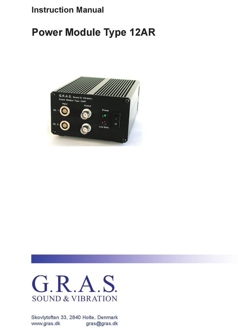
G.R.A.S. 12HM User manual

Instruction Manual
Power Module Type 12HM
Skovlytoften 33, 2840 Holte, Denmark
SOUND & VIBRATION
G R A S
...
.

Revision 05 12 2012
Power Module
Type 12HM

G.R.A.S. Sound & Vibration
CONTENTS
1. Introduction and Description ......................................3
1.1 Polarization Voltage ................................................3
1.2 PreamplierVoltageSupplies . . . . . . . . . . . . . . . . . . . . . . . . . . . . . . . . . . . . . . . . . 3
1.3 Input/Output ......................................................3
1.4 PowerSupply .....................................................4
2. External Features ................................................5
2.1 Front Panel . . . . . . . . . . . . . . . . . . . . . . . . . . . . . . . . . . . . . . . . . . . . . . . . . . . . . . . 5
2.2 Rear Panel .......................................................6
3. Operation . . . . . . . . . . . . . . . . . . . . . . . . . . . . . . . . . . . . . . . . . . . . . . . . . . . . . . . 8
3.1 PowerSupply .....................................................8
3.2 Calibration. . . . . . . . . . . . . . . . . . . . . . . . . . . . . . . . . . . . . . . . . . . . . . . . . . . . . . . . 8
Based on Channel Sensitivity . . . . . . . . . . . . . . . . . . . . . . . . . . . . . . . . . . . . . . . . . . . . . . . . 8
Pistonphone .............................................................8
3.3 Measurements ....................................................8
4. Service and Repair ..............................................10
5. Specications ..................................................11

G.R.A.S. Sound & Vibration
Power Module Type 12HM - Page 4
Fig. 1.1 Power Module Type 12HM
1. Introduction and Description
TheG.R.A.S.PowerModuleType12HM(Fig.1.1)isa10-channelpowersupplyforthefollow-
ingtypesofG.R.A.S.preampliersandmicrophoneswhenmakinglow-noisemeasurements:
• 1-inchPreamplierType26HFwith1-inchMicrophoneType40EH
• ½-inchPreamplierType26HHwith½-inchMicrophoneType40AH
Withthese,sound-powermeasurentsoflow-noiseproducts,suchasdiskdrives,canbemade
underanechoicand/orsemi-anechoicconditionsaccordingtoIEC3745:1977.
TheType12HMprovides:
• polarizationvoltages(200V)for10condensermicrophones
• voltagesupplies(±15V)forpowering10microphonepreampliers
• individualresponsesetting,PressureorFreeeld,foreachchannel
• individualgainadjustmentof±3dBforeachchannel
1.1 Polarization Voltage
Polarizationvoltagesof200Varesuppliedviathe7-pinLEMOEGA3071Bsocketsonthefront
panel.
1.2 PreamplierVoltageSupplies
Preampliervoltagesuppliesof±15Varesuppliedviathe7-pinLEMOEGA3071Bsocketson
the front panel.
1.3 Input/Output
EachchanneloftheType12HMhasa7-pinLEMOEGA3071BinputsocketfortheG.R.A.S.
microphonepreampliersmentionedabove,viz.Types26HF,and26HH.Fig.2.3showsthe
wiringdiagramofthisinputsocket.
TheoutputofeachchannelisavailableviaastandardBNCsocketfordirectusewithanalyzers,
voltmeters,oscilloscopesetc.

G.R.A.S. Sound & Vibration
Power Module Type 12HM - Page 5
1.4 Power Supply
TheType12HMcanrunfromanominalmains/linesupplyofeither:
• 115VACor
• 230VAC
Avoltagetapisprovidedontherearpanelforselectingoneortheother.Ondelivery,itissetto
230 V AC.

G.R.A.S. Sound & Vibration
Power Module Type 12HM - Page 6
2. External Features
2.1 Front Panel
2.1.1 Power Switch
See Fig. 2.1.
• Power OnLED(green)
ThegreenLEDlightsupwhenevertheunitisswitchedonviatheOn/Off(I/0)toggle
switch.
• Mains/linetoggleswitchOn/Off(I/0)
Formains/lineACsupply.Power OnLEDilluminatedwhenpowerisswitchedon.
Fig. 2.1 On/Off (I/0)switch on front panel
2.1.2 Channel Details
Front-paneldetailsforeachchannelareasshowninFig.2.2.
• Pressure or Freeeldswitch
Forselectingafrequencyresponsecorrespondingtoeitherpressure-microphoneopera-
tionorfree-eldmicrophoneoperation:
Pressure-toselecttheoutputofthecompensatinglter(inthepreamplier)whichgives
thesystemalinearpressure-frequencyresponse.
Free Field-toselecttheoutputofthecompensatinglter(inthepreamplier)whichgives
thesystemalinearfree-eldfrequencyresponseat0°incidence.
• OverloadwarningLED
Lightsinstantaneouslyandonlywhilethereisanoverload;synchronisedwiththeoneon
thepreamplier(Type26HForType26HH).
• Level Adjustmentswitchandpotentiometer
On-enablesthelevel-adjustmentpotentiometer;useasmallscrewdriveronthepotenti-
ometertoadjustthegaininsignallevel(±3dB)
Off-disablesthelevel-adjustmentpotentiometer.
Ineithercase,thesignallevelwillalreadyhavebeenraisedby20dBbythepreamplierto
yieldanominalsystemsensitivityof:
• 1.1V/Pawiththe1-inchpreamplierandmicrophone,or
• 0.9V/Pawiththe½-inchpreamplierandmicrophone
• PreamplierInput
7-pinLEMOEGA3071Binputsocketformicrophonepreamplier.Wiringdiagramshown
in Fig. 2.3
• Ouput
BNCsocketfortheoutputsignaleitherviasignalconditioningordirectlyfromthemicro-
phonepreamplier.
Mains/lineOn/Off
toggleswitch
Power on
LED(green)

G.R.A.S. Sound & Vibration
Power Module Type 12HM - Page 7
2.2 Rear Panel
Therearpanelhasthefollowingfeatures(seeFig.2.4)
• AC Mains 50 - 60 Hz, 35 VA
Inputsocketformains/lineACpowersupply.Centrepinisearth/ground.
• Fuse
Pull-outfuseboxfortwofuses,oneactive(innermost)andonespare.Fuserating:
315mA(Slow)for115VACmains/linesupply,or
160mA(Slow)for230VACmains/linesupply
• Mains Voltage Selector
VoltagetapformatchingtheType12HMtotheavailableACpowersupplyvoltage,select.
• 230foranACmains/linepowersupplyofnominally230VAC,or
• 115foranACmains/linepowersupplyofnominally115VAC
Fig. 2.3 7-pin LEMO EGA 307 1B input socket (exter-
nal view)
Fig. 2.2 Front-panel details for each channel of the Power Module Type 12HM
Leveladjustmentpotenti-
ometer;enabledwhenlevel
adjustmentisswitchedOn
Preamplierinput
OverloadLED(instantaneous)
Responsesettingswitch
Leveladjustmentswitch
Output

G.R.A.S. Sound & Vibration
Power Module Type 12HM - Page 8
Fig. 2.4 Rear panel of the Power Module Type 12HM
ACMains/lineinputsocket
50-60Hz35VA Mains Voltage
Selector:
230 V AC or
115 V AC
Pull-outfusebox,for2fuses,
1active(innermost);1spare

G.R.A.S. Sound & Vibration
Power Module Type 12HM - Page 9
3. Operation
Note:thischapterassumesthattheType12HMisbeingusedwitheitherofthefollowing
G.R.A.S.preampliers(nootherscanbeused):
• 1-inchPreamplierType26HFwith1-inchMicrophoneType40EH
• ½-inchPreamplierType26HHwith½-inchMicrophoneType40AH
3.1 Power Supply
BeforeconnectingtheType12HMtoanACmains/linesupplyandswithcingiton,makesure
the Mains Voltage Selectorontherearpanel(seeFig.2.4)matchesthelocalACvoltage
supply.Select:
• 230foranACmains/linepowersupplyofnominally230VAC,or
• 115foranACmains/linepowersupplyofnominally115VAC
Checkalsothatthecorrectfuseisinplaceandnotblown(seeFig.2.4).
3.2 Calibration
3.2.1 Based on Channel Sensitivity
SincethemicrophonesignalisampliedinthePreamplierby20dB,thenominalsensitivityat
theoutputofthechannelinquestioncorrespondsto:
• 1.1V/Pawiththe1-inchpreamplierandmicrophone,or
• 0.9V/Pawiththe½-inchpreamplierandmicrophone
Correspondingly(ifLevel AdjustisswithchedOff-seeFig.2.2),whenthemeasuredRMS
outputvoltagefromthechannelis1.1Vor0.9V,themicrophoneinquestionisbeingsubjected
to94dBre.20μPa.
Basedonthisinformation,proceedasfollows:
1. Connectthechanneloutputtotheanalyzertobeusedandswitchbothunitson.
2. Adjusttheanalyzertoindicate94dBre.20μPaforanRMSinputofSvolts;whereSis the
sensitivity(1.1V/Paor0.9V/Pa,seeabove)ofthechannelinquestion.
3.2.2 Pistonphone
AG.R.A.S.PistonphoneType42AAttedwithaG.R.A.S.CouplerRA0090canbeusedtopro-
duce94dBre.20μPaonamicrophone.
Note:aPistonphonettedwithanormal1-inchcoupler(RA0023)cannotbeusedbecausethis
willoverloadthechannelwithalevelof114dBre.20μPa.
Proceedasfollows:
1. Connectthechanneloutputtotheanalyzertobeusedandswitchbothunitson.
2. UnscrewandremovethenormalcouplerofthePistonphone.
3. ScrewtheCouplerRA0090tothePistonphone,seeFig.3.1.
4. InsertthemicrophoneofthechannelinquestionintheCouplerasshowninFig.3.2and
switchthePistonphoneon.Note:fora½-inchmicrophone,usetheadapterGR0619sup-
pliedwiththeCouplerRA0090.
5. Adjusttheanalyzertoindicate94dBre.20μPa.
3.3 Measurements
1. Connectthepreamplier(withmicrophone)totheLEMOEGAinputofthechannelinques-
tion.
2. Connecttheoutputfromthechanneltoananalyzer

G.R.A.S. Sound & Vibration
Power Module Type 12HM - Page 10
3. Switchonbothunits
4. Calibratethesetupviaoneofthemethodsdescribedinsection3.2.
5. SelectwhichmicrophoneoperationtouseviatheswitchonthefrontpanelmarkedPres-
sure/Free Field(seeFig.2.2).
Atthispointyoucanmakeyourmeasurementsbutkeepaneyeontherelevantoverloadwarn-
ingLEDs(oneonthefrontpanelforeachchannelandoneonthepreamplier)toavoidover-
loadingthesystemandinvalidatingthemeasurements.
Fig. 3.1 Pistonphone without its normal coupler and ready to accept the
Coupler RA0090
Fig. 3.2 Pistonphone tted with Coupler RA0090 and the microphone
inserted into the Coupler

G.R.A.S. Sound & Vibration
Power Module Type 12HM - Page 11
4. Service and Repair
Repairsshouldbecarriedoutonlybyqualiedpersonal.ThePowerModuleType12HMshould
notbedismantledwithpoweronbecauseofhigh-voltagecircuits.

G.R.A.S. Sound & Vibration
Power Module Type 12HM - Page 12
5. Specications
Input/Output sockets per channel:
Input: 7-pinLEMOEGA3071B
Output: BNCcoaxial
Gain Adjustment per channel:
±3dB
Frequency response:
with1-inchPreamplierType26HFand1-inchMicrophoneType40EH
10Hz-10kHz ±2.0dB
12.5Hz-4kHz: ±1.0dB
6Hz-12.5kHz: +2.0dB,–3.0dB
with½-inchPreamplierType26HHand½-inchMicrophoneType40AH
10Hz-16kHz ±2.0dB
12.5Hz-10kHz: ±1.0dB
6Hz-20kHz: +2.0dB,–3.0dB
Nominal sensitivity:
with1-inchPreamplierType26HFand1-inchMicrophoneType40EH
Channel: 1.1V/Pa
Microphone: 110mV/Pa
with½-inchPreamplierType26HHand½-inchMicrophoneType40AH
Channel: 0.9V/Pa
Microphone: 90mV/Pa
Microphone polarization voltage:
200 V
Channel separation:
20Hz-20kHz: >90dB
Output impedance:
30Ω
Output voltage:
Max: ±10Vp-p
Power supply:
Mains/line: 115Vor230VAC(nominal)
Power consumption:
With10G.R.A.Spreampliers 35VA
Fuse:
315mA(Slow)for115VACmains/linesupply,or
160mA(Slow)for230VACmains/linesupply
Operating temperature range:
-10°Cto+50°C

G.R.A.S. Sound & Vibration
Power Module Type 12HM - Page 13
Dimensions:
Height: 132.6mm(5¼in)
Width: 420.0mm(16½in)
Depth: 196.0mm(7.7in)
Weight:
5.5kg(12.1lbs)
Accessories included:
Mains/linecable
Accessories available:
Type26HF 1-inchpreamplier
Type40EH 1-inchmicrophone
Type26HH ½-inchpreamplier
Type40AH ½-inchmicrophone
WEEEdirective:
2002/96/EC
CEmarkingdirective:
93/68/EEC
Manufacturedtoconformwith:
RoHSdirective:
2002/95/EC
Table of contents
Other G.R.A.S. Control Unit manuals
Popular Control Unit manuals by other brands

DEUTSCHMANN AUTOMATION
DEUTSCHMANN AUTOMATION LOCON 200 instruction manual

LOVATO ELECTRIC
LOVATO ELECTRIC EXP10 16 instruction manual

Acconeer
Acconeer XM112 Hardware user's guide

Bticino
Bticino 375000 quick start guide

Leviton
Leviton Decora Illumatech RTF01-10 installation instructions

Supermicro
Supermicro MicroBlade MBI-6219G-T8HX user manual