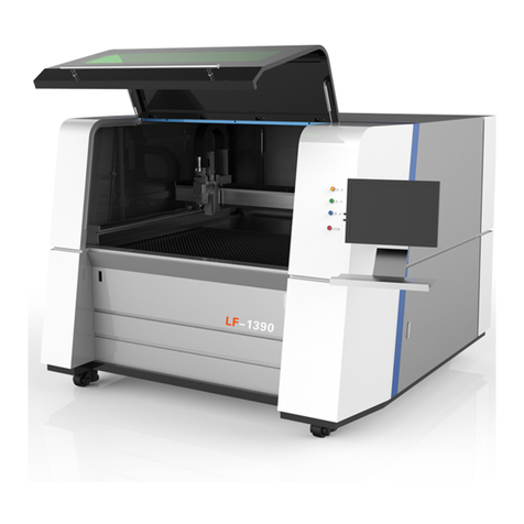
G-WEIKE LC Series User manual

LC、LG Serial Machine
使用说明书
OPERATION MANUAL
This owner's manual is suitable for:
Laser machine designer
Laser machine operator

1
Copyright Statement
Jinan G.Weike Science & Technology Co.,Ltd
All rights reserved.
G.Weike Science&Technology Co.,Ltd(hereafter referred to G.weike) reserves the right to
modify the products and product specifications described in this manual without advance notice.
G.Weike is not responsible to any direct, indirect, or consequential damage or liability
caused by improper use of this manual or the product.
G.Weike owns the patent, copyright or any other intellectual property right of this product
and the related software. No one shall duplicate, reproduce, process or use this product and its
parts, unless authorized by our company.
All the name refered in this manual only for identification, if belongs to other company's
registered trademark or copyright, proprietary rights of the name belongs to their respective
Holder.
Disclaimer and Responsibility Statement
Whole using the machine from our company, users are required to ensure integrity and
independence of the product including but not limited to: mechanical, electrical, optical, control
software and accessories. Unauthorized modification is strictly prohibited it is a must to satisfy
operating environment and operating specifications specified in the owner's manual.
For the followings:
1. Machine modified with no authorization (including but not limited to: add, remove,
modify, unauthorized disassembly, replacing parts);
2. Use the machine in the environment failing to satisfy the operating requirements;
3. Operate disobeying the specifications of our company;
4. Unauthorized use the machine parts, accessories and auxiliaries on to other equipment
or in other places;
5. Viciously disassemble, destroy, decode hardware and software of the equipment from
our company
Our company shall not undertake any direct, indirect or joint responsibility. Our company
reserves the rights to ascertain legal responsibility for the serious consequences or economic
losses or reputation losses caused by what mentioned above.
Foreword
Thanks for purchasing the laser engraving machine control system of our company.
Before operating, please read this manual carefully to ensure proper operation.
Please keep the manual properly for reference.
Since the configs are different, certain models do not have the functions listed in this
manual. Please refer to the specific functions for details.
Due to the constantly tech update, the specification for reference only, subject to the real
Standard. Tags in this book:
Alarm:Special Attention: User must follow and perform as the manual; otherwise, it could
lead to errors or relatively serious problem.

2
Safety Precautions
Attention
◆Before using the machine. users are required to carefully read this manual and other
operating requirements, strictly abide by the operating specifications.
Professional are required for operating the machine.
◆The machine uses class 4 laser (strong laser radiation ). The laser radiation may possibly
cause the following accidents: ①emblaze the surrounded flammable materials; ②generate
other radiations and toxic or hazardous gas by processed objects during laser processing; ③
direct irradiation of laser radiation cause harm to human body. Therefore. fire fighting devices
are required in the operating place of the machine. Stacking flammable or explosive objects near
the machine is strictly prohibited. Good ventilation is a must. Only the qualified personnel are
authorized to approach the machine.
◆The processed objects and discharged materials are required to satisfy requirements as
per local laws and regulations.
◆Laser processing is with potential risks. Users should carefully make sure if the
processed objects are suitable for laser processing.
◆There is high voltage and potential risk in the laser machine . Unauthorized disassembly
by unqualified personnel is prohibited.
◆Reliable earthing is required for the machine and related other equipment before
power-on.
◆During operating, removing any cover of the equipment is strictly prohibited.
◆During operating, the operators are required to observe working status of the machine all
the time. in case of any abnormality. it is immediately to disconnect power supply and take active
and corresponding measures.
◆After power-on. special personnel are required for monitoring Unauthorized leaving is
strictly prohibited
◆It is a must to disconnect the power supply before leaving.
◆It is strictly prohibited to placing any unrelated all-reflective or diffusion reflective
objects in the machine to prevent laser reflecting to human body or flammable materials.
◆The environment for the machine should be dry. free of interference and influences from
pollution, vibration, high voltage and strong magnet. The operating ambient temperature ranges
5- 40℃. and the humidity ranges 5-95% (no dew);
◆The machine should be far from electric appliances sensitive to electromagnetic
interference;
◆Operating voltage: AC220V. 50Hz. Power-on is strictly prohibited in case of unstable
voltage of the power grid or unspecified voltage.
Chapter two of this manual is for Safety Rules. Please refer to the chapter more details
concerning safe operation of the equipment. Users are required to carefully read and abide by all
the requirements of safety.
Note:Note: User Should Comply With the attention and Suggestion in this manual; it
could bring much easier operation.

3
Contents
Copyright Statement ……………………………………………………………………………1
Disclaimer and Responsibility Statement………………………………………………………1
Foreword…………………………………………………………………………………………1
Safety Precautions…………………………………………………………………………………2
Chapter 1 Machine introduction …………………………………………………………………6
1.1 Instructions of machine model………………………………………………………………6
1.2 Machine compositions ………………………………………………………………………7
1.2.1 Compositions of the machine ………………………………………………………………7
1.2.2 Compositions of movement mechanism…………………………………………………10
1.2.2.1 Plane movement mechanism ……………………………………………………………10
1.2.2.2 Lift move ment mechanism………………………………………………………………12
1.2.2.3 Rotary device mechanism ………………………………………………………………21
1.2.3 Optical mechanism…………………………………………………………………………24
1.2.4 Electric dual-laser head mechanism ………………………………………………………26
1.2.5 Machine visual mechanism ………………………………………………………………27
1.2.6 Mesh belt feeder type………………………………………………………………………8
1.2.7 Working platform …………………………………………………………………………9
1.2.8 Auxiliary parts ……………………………………………………………………………9
1.3 Equipment parameters………………………………………………………………………10
1.4 System configuration………………………………………………………………………12
1.5 Operating environment………………………………………………………………………13
1.6 Suitable materials …………………………………………………………………………13
1.7 Applicable fields……………………………………………………………………………13
Chapter 2 Safety Rules…………………………………………………………………………14
2.1 Product safety. ………………………………………………………………………………14
2.2 Safe equipment……………………………………………………………………………….14
2.3 Safety awareness……………………………………………………………………………14
2.4 Requirements for personnel ………………………………………………………………14
2.4.1 Definition of terms…………………………………………………………………………15
2.4.2 Qualifications ……………………………………………………………………………15
2.4.3 Responsibility ……………………………………………………………………………15
2.4.4 Personal protective devices………………………………………………………………15
2.5 Special product risks…………………………………………………………………………16
2.5.1 Laser radiation risk…………………………………………………………………………16
2.51.1 Common mode……………………………………………………………………………16
2.5.1.2 Maintenance mode………………………………………………………………………16
2.5.1.3 Direct laser ……………………………………………………………………………17
2.5.1.4 Reflection and diffuse radiation…………………………………………………………17
2.5.2 High voltage risk…………………………………………………………………………17
2.5.3 Risk of electric shock………………………………………………………………………18
2.5.4 Hazard of processing outgrowth…………………………………………………………19
2.5.5 Risk of optical system……………………………………………………………………19

4
2.5.5.1 Routine operation ………………………………………………………………………20
2.5.5.2 Warning for fire accident…………………………………………………………………20
2.5.6 other risk………………………………………………………………………………… 20
2.5.7 emergency accident solvement……………………………………………………………20
2.5.7.1 treament measures of personal injury …………………………………………………20
3.5.7.2 Fire treament measures …………………………………………………………………20
Chapter 3 Machine Installation And Debugging…………………………………………………21
3.1 Machine Installation………………………………………………………………………21
3.1.1 Steps of unpacking…………………………………………………………………………23
3.1.2 Unpacking check …………………………………………………………………………24
3.1.3 Preparations for equipment installation……………………………………………………25
3.1.4 Steps of installation ………………………………………………………………………25
3.1.4.1 Laser tube installation …………………………………………………………………25
3.1.4. 2 Laser power supply installation…………………………………………………………27
3.1.4.3 Water cooling system installation………………………………………………………28
3.1.4.4 Air pump installation……………………………………………………………………29
3.1.4.5 Blower installation ……………………………………………………………………30
3.1.4.6 Equipment earthing ……………………………………………………………………30
3.1.4.7 Removal of fixation block ………………………………………………………………31
3 1.4.8 Cutting head installation…………………………………………………………………32
3.1.4.9 Software and machine drive installation.………………………………………………33
3.1.4.10 0ther auxiliary part installation…………………………………………………………33
3.2 Equipment debugging………………………………………………………………………34
3.2.1 Sequence of power-on and power-off.……………………………………………………34
3.2.2 Movement debugging……………………………………………………………………34
3.2.2.1 Motor shaft movement…………………………………………………………………34
3.2.2.2 Resolution setup…………………………………………………………………………35
3.2.2.3 Stroke,limit and reset……………………………………………………………………36
3.2.2.4 Straightness and perpendicularity ………………………………………………………37
3.2.3 Laser debugging …………………………………………………………………………37
3.2.3.1 Light emitting test ………………………………………………………………………37
3.2.3.2 Light route adjustment…………………………………………………………………39
3.2.4 Trial operation of processing ……………………………………………………………40
Chapter 4 System Maintenance…………………………………………………………………41
4.1 Mechanical maintenance……………………………………………………………………41
4.1.1Guide rail,linear shaft,slide block assembly (metal guide pulley),nylon guide pulley ……41
4.1.2 Synchronous belt. synchronous belt wheel ………………………………………………42
4.1.3Fasten screws and coupling ………………………………………………………………42
4.2 Electric maintenance ……………………………………………………………………42
4.2.1 Limit switch ………………………………………………………………………………42
4.2.2 Maintenance of each button and indicators ………………………………………………43
4.3 Light route maintenance ……………………………………………………………………43
4.4 Auxiliary parts maintenance ………………………………………………………………44
4.4.1 Water replacement and water tank cleaning ………………………………………………44

5
4.4.2 Blower cleaning……………………………………………………………………………44
4.4.3 Water chiller maintenance ………………………………………………………………44
Chapter 5 Trouble Shooting ……………………………………………………………………45
Appendix ………………………………………………………………………………………46
Appendix1 Electric wiring diagram for No.1(1.1) controller ………………………………46
Appendix2 Electric wiring diagram for No.2 controller ……………………………………47
Appendix3 Electric wiring diagram for No.3 controller……………………………………48
Post ……………………………………………………………………………………………49

6
LC,LG Series equipment operating instructions
LC LG serial laser machine is a universal low power laser processing device developed by our
company Jinan G.Weike Science &Technology Co., Ltd. The machine is mainly equipped with
sealed max. 200W C02 glass laser tube or metal radio-frequency tube with the function of cutting
and carving common non-metal materials and with the wide scope of application in the fleld of
printing, advertisement, garment.,leather and electronics.
1.1 Instructions of machine model
Indications of G.weike laser machine model:
LC ×××× ×—×××
Additional code(ie import laser power)
Structure feature code(blank—belt;S—ball
screw;C—camera)
Main spec:cutting size(the front two is
width、back two is length)
GWEIKE laser machine(L—laser;C—cut)
From the figure above,we can know:
LC1290 —— indicate cutting breadth of 1200*900mm,belt moving laser cutting machine by
Gweike company
×× ×× ×× ×
Additional code(new or modified )
Y direction route
X direction route
GWEIKE cnc engrave code(LG—laser;
WK—cnc router)
Model example :

7
LG6040N—— indicate cutting breadth of 600*400mm,new design cnc laser engaver produced
by Gweike laser
WK1325 —— indicate cutting breadth of 1300mm*2500mm cnc router produced by gweike
laser
Fig 1.1 Instructions of machine model
LC,LG serial laser machine is a device with the largest seal volume and most wide range of
application of our company and with various models. This manual contains general operation
instructions for the serial equipment including installation, mechanics,electrics,light route, use
and maintenance of control software. Due to the special model or special field of application of.
some special machine types,we will provide additional extra instructions for them. Owner's
Manual is subject to the manual attached to the equipment.
ATTENTION!
As time goes by,naming rules of some models may possibly be different from what mentioned
above.And they are subject to the actual product model and manual attached.
1.2 Machine compositions
Due to different models and improvement of products, the industrial design and details of
some types of machine may be different. The compositions are subject to the actual product .The
following takes general LG1290 as an example for the compositions of the machine.
1.2.1Compositions of the machine
Front view of the machine is as shown in the figure below:

8
Fig1-2
①Main unit(material collector included)
②Y-axis movement mechanism
③Laser head
④Machine crossbeam
⑤Working table (Beehive or strip soleplate)
1
2
3
4
5
6
7
8
9
10
12
11
13
14
15
16
17
18

9
⑥X-axis movement mechanism
⑦Foot wheel and footmaster caster
⑧Control panel
⑨Potentiometer (Power adjusting knob)
⑩Laser switch
⑪Ampere meter (Power indicator)
⑫Laser outlet (Each one at left and right)
⑬Upper cover of the machine
⑭Gas spring (Each one at left and right)
⑮Left end cover of the machine
⑯Cabinet door of left case
⑰The electric fan
⑱Data interface (USB or network interface)
⑲Safety switch magnet
⑳Safety switch
Back view of the machine is as shown in the figure below:
Fig 1-3
19
20
9
21
9
22
9
23
9
24
9
25
9
26
9
29
9

10
19 laser tube cover
20 right end cover of the machine
21 Master switch of power supply
22 Master power cord of the machine
23 Exhaust blower
24 Ventilation outlet (to exhaust blower)
25 Air blower
26 water chiller
27 Water pipe and air pipe joint
28 water protect signal connector
29 Back door of case (Laser power box)
Machine control is as shown in the figure below:
Fig.l-4 illustration of machine control
1.2.2 Compositions of movement mechanism
1.2.2.1 Plane movement mechanism
lane movement mechanism is composed of X-axis and Y-axis movement mechanisms in
vertical relation as shown in the figure below:
control system
Optical institutions
motion institution
Visual institutions
exhaust fan
water chiller
air pump

11
Fig1-5
①X-axis motor
②X-axis beam and guide rail
③X-axis timing belt
④Dolly (connecting to cutting head)
⑤X-axis sensor (Reset or limit signal)
⑥Y-axis guide rail (each one at left and right)
⑦Y-axis guide rail beam (each one at left and right)
⑧Y-axis drive shaft
⑨Y-axis motor
⑩Y-axis sensor (Reset or limit signal)
⑪Y-axis timing belt (each one at left and right)
The figure below is an illustration of another plane movement mechanism mainly used in
processing machine with larger breadth The differences lie in installation position and
configuration of movement parts.
①X-axis
②X-axis beam and guide rail
③X-axis timing belt
④Dolly (connecting to cutting head)
⑤X-axis sensor (Reset or limit signal)
⑥Y-axis guide rail (each one at left and right)
⑦Y-axis guide rail beam (each one at left and right)

12
⑧Y-axis drive shaft
⑨Y-axis motor
⑩Y-axis sensor (Reset or limit signal)
⑪Y-axis timing belt (each one at left and right)
Fig1-6
1
2
3
4
5
6
7
8
9
10
11

13
LG5030 front picture as follows:
Fig 1-7
1. machine body
2.x axis moving system
3.control panel
4. Laser switch(laser set)
5. Laser outlet
6. Machine upper cover
7. Gas spring(for support upper cover,left and right each)
8. USB( flash memory slot)
9. Safety switch magnetic
10. Safety switch
11. Waterin,waterout and air out
1
2
3
4
5
6
7
8
10
9
11

14
Back of LG5030 laser machine picture:
Fig1-8
12 Laser power socket
13 Control case
14 Laser tube cover
15 Air hose
12
13
14
15

15
LG6040N outlook:
Fig1-9
1. machine body
2.x axis moving system
3.control panel
4. Laser switch(laser set)
5. Laser outlet
6. Machine upper cover
7. Gas spring(for support upper cover,left and right each)
8. USB( flash memory slot)
9. Safety switch magnetic
10. Safety switch
1
2
3
4
5
6
7
8
/
9
/
10
/
11
/
12
/
13
14

16
11. Control case
12. Power switch
13. Emergency switch
14. Anmeter
LC1325M schematic diagram:
图1-10
1.Machine body(include container)
2.Y axis moving system
3.Laser head
4.Machine beam
5.Working platform
6.X axis moving system
7.Basement
8.Control panel
9.Machine upper cover
1
2
3
4
5
6
7
8
9
10
11
0
12
0

17
10.Z axis motor
11.Key switch
12.Emergency switch
LC1325M moving system schematic diagram
1
2
3
4
5
6
7
8
9
10

18
Fig 1-11
1.
2.Z axis guide linear
3.Z axis ball screw
4.Y axis left guide linear
5.Y axis ball screw
6.X axis ball screw
7.Y axis right guide linear
8.X axis motor
9.X axis coupling
10.Y axis motor
1.2.2.2 Lift movement mechanism
Some types of machine are with life platform function (e.g. LG1290). The life platform
mechanism is as shown in the figure below:
1
5
4
2
3

19
Fig1-12
①Working platform
②Life motor
③Motor stand
④Lift guide rail (two each at left and right}
⑤Lift ballscrew (one each at left and right)
LG6040N working table configure as follows:
Fig 1-13
1.Z axis beam and guide rail(each one at left and right)
2 Auto ball screw(each one at left and right)
3.Z axis belt protect case
1
2
3
4
This manual suits for next models
1
Table of contents
Other G-WEIKE Cutter manuals