GA DUROVENT FIGURE 925SS User manual

Manual Number 925SS-IOM-111120 Rev A
INSTALLATION, OPERATION AND
MAINTENANCE MANUAL
FIGURE 925SS
DUROVENT™AIR RELEASE VALVES
FOR SEWAGE & WASTEWATER
TABLE OF CONTENTS
Introduction ….………………………… 2
Description of Operation .....………… 2
Receiving & Storage .....……………… 2
Installation ......…………………………. 2
Valve Construction ......………………. 3
Preventive Maintenance ....………….. 3
Testing/Trouble Shooting ...…………… 3
Disassembly ....………………………… 3
Assembly ....……………………………. 4
Backflushing Instructions …………… 4
Order Replacement Parts …………….. 5
Repair Kits ……………………………… 5
Warranty .……………………………….. 5
Figure 925SS Drawing/Parts List ….…. 5
234 Clay Avenue • Mars, PA 16046 USA
Telephone (724) 776-1020 • Fax (724) 776-1254
E-mail: info-ga@vag-group.com

2
INSTALLATION, OPERATION and
MAINTENANCE
Figure 925SS Sewage Air Release Valves
INTRODUCTION
This manual will provide the information to
properly install, operate and maintain the valve
to ensure a long service life. The Air Release
Valve is ruggedly constructed to provide years of
trouble-free operation with minimal
maintenance.
CAUTION
The valve is NOT recommended for use with
toxic fluids, fuels or fluids containing hazardous
gases
CAUTION
The valve will not function if used at a pressure
higher than the maximum working pressure
indicated on the nameplate.
The Shop Order (SO) Number, Figure Number,
size and pressure rating are stamped on a
nameplate attached to the valve. Please refer to
the SO number when ordering parts.
DESCRIPTION OF OPERATION
The Figure 925SS Durovent™Air Release
Valve is designed to automatically vent air and
sewage gas that has accumulated within the
valve. These valves are usually installed at high
points in the system where air tends to collect.
The valve as shipped is ”normally-open” and will
vent air through its orifice at the top of the valve.
The float rises when water enters the valve and
closes the orifice. Air from the system
accumulates in the valve forcing the water level
down until the float drops and opens the venting
orifice. As air is released the water level rises
lifting the float and re-closing the valve.
This sequence occurs as often as necessary to
release air that has collected in the valve.
RECEIVING AND STORAGE
Inspect the valve upon receipt for damage
during shipment. Carefully unload all valves to
the ground without dropping.
The valves should remain in a clean, dry and
weather protected area until installed. For long
term storage (greater than 6 months) the rubber
surfaces of the seat should be coated with a
non-toxic lubricant such as "SuperLube" made
by Synco Chemical. Do not expose the rubber
parts to sunlight or ozone.
INSTALLATION
The Figure 925SS is standard with 2” or 3” NPT
screwed connections. A flanged pipeline
connection is provided on special order.
Consult the drawings of record to verify the
configuration supplied and installed.
The valve must be installed in an upright vertical
orientation, normally at a high point in the
system.
If installed outdoors, below ground in a vault or
in an unheated area, adequate freeze protection
must be provided.
An isolating valve should be installed between
the valve and the pipeline or system to facilitate
maintenance (included with backflushing
attachments).
Carefully screw threaded end valves onto pipe
nipple using compatible thread sealant. Tighten
valve using wrench flats. DO NOT OVER-
TIGHTEN.
Flat-faced flanged valves should be mated with
flat-faced flanges and full-face gaskets. If ring
gaskets are used the bolt material shall be
ASTM A307 Grade B (or equivalent). Higher
strength bolting should only be used with full-
face gaskets.
Lower heavy valves over the mating flange
using slings or chains around the valve body.
Lubricate the bolts or studs and insert around
flange. Lightly tighten bolts until gaps are
eliminated. Torque bolts in an alternating

3
pattern in graduated steps. If leakage occurs
wait 24 hours and re-torque the bolts but do not
compress the gasket more than 50% or exceed
bolt maximum torque rating.
VALVE CONSTRUCTION
The standard Figure 925SS Durovent™Sewage
Air Release Valve has a cast 315SS body and
cover, 316 stainless steel float and linkage
mechanism and a rubber seat. Refer to the List
of Materials submitted for the order if non-
standard materials were provided.
Refer to Page 5 for details of construction and
parts location.
The Figure 925SS has a 10 to 150 PSI working
pressure range while the Figure 927SSL has a
10 to 75 PSI working pressure range.
The valve has an inlet connection at the bottom
where the valve attaches to the system and a
smaller outlet connection at the top through
which air leaves the valve.
WARNING
Removing the valve from the line or
disassembling the valve while there is pressure
in the valve body may result in injury or damage
to the valve
PREVENTIVE MAINTENANCE
Figure 925SS Durovent™Sewage Air Release
Valves require no scheduled lubrication or
adjustment.
A periodic visual inspection should be performed
to ensure the outlet piping is not obstructed and
to verify there is no fluid leakage.
Depending on the nature of the fluid, sewage air
valves may become clogged with sediment or
grease and require periodic cleaning. To
facilitate such cleaning VAG/GA Industries air
valves with an “F” at the end of the Figure
Number (e.g., 925SSF, 925SSLF) were supplied
with “backflushing attachments.” Refer to the
backflushing instructions on Page 4 of this
manual for additional information.
TESTING
Valve operation can be easily tested. Close the
inlet isolation valve and remove or loosen the
pipe plug nearest the inlet to drain the water
from the valve. The float should drop as the
water leaves the valve. NOTE: A manual valve
can be installed in place of the pipe plug to
facilitate testing (valves are included with
backflushing attachments).
Replace or tighten the pipe plug and slowly open
the inlet isolating valve. After expelling air, the
valve should close and seal tightly.
TROUBLESHOOTING
•Valve Does Not Close / Fluid Leakage
Verify debris has not collected on the seat
preventing tight closure
Verify rubber orifice button and/or orifice
seating surfaces are not damaged
Verify float has buoyancy
Verify linkage mechanism operates freely
without binding or sticking
Verify the pressure at the valve inlet it at
least 10 PSI
•Valve Does Not Open
Verify debris in the valve is not
preventing the float from freely falling
when fluid is drained from valve
Verify linkage mechanism operates freely
without binding or sticking
Verify the pressure at the valve inlet does
not exceed the valve’s maximum working
pressure
DISASSEMBLY
While small valves may be more easily serviced
by removing it from the line, all valves can be
serviced while the body remains connected to
the pipeline. A skilled technician with proper
tools should perform all work. No special tools
are required.
Disassemble the valve only as far as needed to
replace damaged or worn parts.
First ensure there is no pressure within the
valve. Remove the cover bolts (16) and lift off
cover (2) with float and linkage attached. It may
be necessary to pry the cover off. Be careful not
to damage or lose the O-ring (10) unless it’s
being replaced.
Remove the two spring pins (13) connecting the
lever arm (11) and float arm (12) to the bracket
2

4
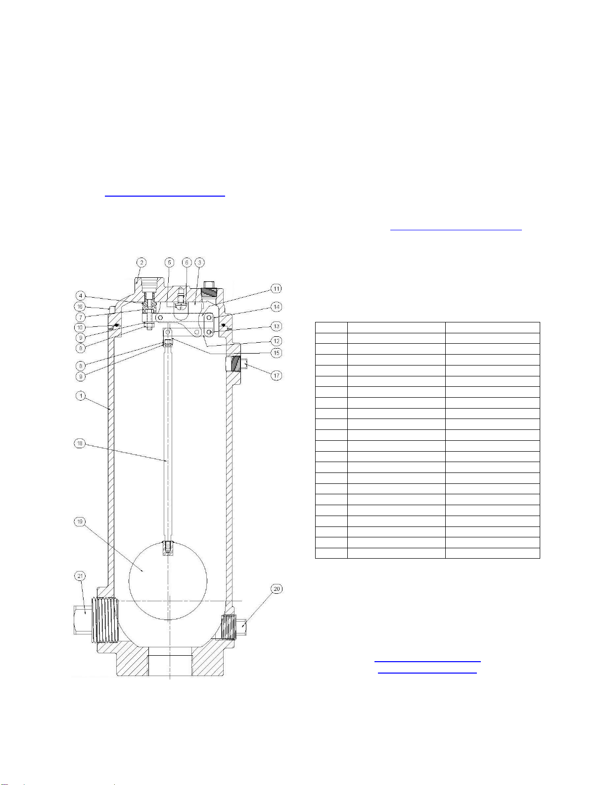
(3). The float and linkage will be free from the
cover.
Remove the spring pins (13) connecting the
valve links (14) to the float arm (12). Remove
the spring pin (13) from the pivot link (15) and
the hex nut (8) and lock washer (9). Unscrew the
float rod (21) from the float ball (20). It may be
necessary to apply some heat to these threaded
connections as they are secured with Loctite.
Remove the hex nut (8) and lock washer (9) and
unscrew the orifice button (7) from the lever arm
(11).
Remove the bracket screw (5) to remove the
leverage bracket (3). Using a hex socket
remove the orifice (4) from the cover.
Inspect all parts for wear and damage. Minor
scratches and dents in the float are normal.
Some floats may contain sand for added weight
but if water is detected replace the float.
Carefully clean the orifice of scale. Replace
damaged parts.
REASSEMBLY
Clean all parts especially seating and sealing
surfaces before reassembling valve. Worn parts
should be replaced during re-assembly.
Apply Loctite©PST thread sealant to orifice (4)
and thread into cover. Torque to 22 ft-lbs
(maximum).
Install bracket (3), bracket screws (5) and lock
washers (6) and tighten.
Thread orifice button (7) all the way into lever
arm (11) and install hex nut (8) and lock washer
(9) but do not tighten. Connect the lever arm
(11) and float arm (12) to the bracket (3) using
two spring pins (13).
Adjust the orifice button (7) so that the end of
the lever arm (11) nearest the orifice button is
about 1/16” (1.6mm) farther from the cover than
the opposite end when the orifice button (7) is
gently resting on the orifice (4). Secure by
tightening hex nut (8).
Install valve links (14) and spring pins (13) to
connect the float arm (12) to the lever arm (11).
Apply Loctite 263 to one end of float rod threads
and Install lock washer (9) and float rod (21) into
float ball (20) and tighten. Apply Loctite 263 to
the threads on the other end of float rod. Install
pivot link (15), lock washer (9) and hex nut (8)
on opposite end of float rod (19) and tighten.
Attach pivot link (15) to float arm (12) using
spring pin (13).
Verify free movement of linkage mechanism and
that the orifice button (7) presses against the
orifice (4) when the float rises and pulls away
when allowed to fall.
Lubricate and place O-ring (10) in cover (2) and
carefully place cover (2) on body (1) ensuring o-
ring is retained. Install the cover bolts (16) and
tighten in an alternating pattern.
Carefully introduce pressure and check for
leaks.
BACKFLUSHING INSTRUCTIONS
Follow all local cross-connection and safety
codes and regulations!
To determine if a GA Industries sewage air valve
needs cleaning or backflushing:
•Close the inlet isolating valve then slowly
open the ½” flushing ball valve (if installed)
or slowly remove the pipe plug at the top
of air valve to relieve internal pressure.
•Open the 1” blow off ball valve (if installed)
or remove the pipe plug near the bottom.
Liquid should freely drain from the valve
body. If it does not, then the valve is likely
in need of cleaning or backflushing.
To clean a GA Industries sewage air release
valve equipped with backflushing attachments:
•Close the inlet isolating valve and then
slowly open the ½” flushing valve to
relieve internal pressure.
•Open the 1” blow off valve
•Connect the ½” flushing valve to a
pressurized source of clean water using
the rubber hose provided with the
backflushing attachments.
•Introduce flushing water until liquid runs
freely from the blow off valve.
•Shut off and disconnect the supply of
clean water and close the blow off and
flushing valves.
•Slowly open the inlet isolating valve. The
air release valve should exhaust air and
then close tightly

5
REPLACEMENT PARTS
Genuine replacement parts are available from
your local VAG/GA Industries representative or
from the factory:
VAG USA, LLC
234 Clay Avenue
Mars, PA 16046 USA
Telephone: 724-776-1020
Fax: 724-776-1254
E-mail: quotes-ga@vag-group.com
Please have the nameplate data available when
ordering parts.
REPAIR KITS
Soft Goods Kit A925 (Part Number 2-80-11000-
008) contains Items 7, 8, 9 and 10
Linkage Kit AL925 (Part Number 2-80-11000-
084) contains Items 3, 5, 6, 11, 12, 13, 14, 15
and 20.
Other parts are ordered individually
WARRANTY
The Warranty for GA Industries valves is
included in our Terms and Conditions which can
be found here: https://gaindustries.com/terms
Figure 925SS Durovent™Air Release Valve
Parts List
Item
Description
Standard Material
1
Body
316 Stainless Steel
2
Cover
316 Stainless Steel
3
Leverage Bracket
316 Stainless Steel
4
Orifice
316 Stainless Steel
5
Bracket Screw
304 Stainless Steel
6
Lock Washer
410 Stainless Steel
7
Orifice Button
Buna-N Rubber/SS
8
Hex Nut
304 Stainless Steel
9
Lock Washer
410 Stainless Steel
10
O-Ring
Buna-N Rubber
11
Lever Arm
316 Stainless Steel
12
Float Arm
316 Stainless Steel
13
Spring Pin
302 Stainless Steel
14
Valve Link
316 Stainless Steel
15
Pivot Link
316 Stainless Steel
16
Cover Bolt
316 Stainless Steel
17
½” Pipe Plug
316 Stainless Steel
18
1”Pipe Plug
316 Stainless Steel
19
2”Pipe Plug
316 Stainless Steel
20
Float Ball
316 Stainless Steel
21
Float Rod
316 Stainless Steel
VAG USA, LLC
234 Clay Avenue •Mars, PA 16046 USA
Phone: 724-776-1020 •Fax: 724-776-1020
info-ga@vag-group.com
www.gaindustries.com
Table of contents
Other GA Control Unit manuals
Popular Control Unit manuals by other brands

Siemens
Siemens SIMATIC 8DO DC24V/0.5 A manual

Beninca
Beninca RI.10KI operating instructions

Measurement Computing
Measurement Computing PCI-DDA08/12 user guide

DOMUS Ventillation
DOMUS Ventillation ANC118A installation instructions

Matrix Orbital
Matrix Orbital LK202-24-USB Technical manual

NI
NI IMAQ PCI-1409 user manual

Apollo Valves
Apollo Valves BFMM RP4A SBF Installation, operation and maintenance manual

Parker Hydraulics
Parker Hydraulics GRESEN V10 Service manual

Festo
Festo CPE-10-PRS series operating instructions

Flowstar
Flowstar CT5-1 Installation and operating manual

VALVEX
VALVEX 4700330 Assembly and operation instructions

Stahl
Stahl 9442/35 Series operating instructions