GABOR TM-3255 User manual

TM-3255, TM-3770 /TILTING
TVMOUNT
with Post-Installation Adjustment
for 32 – 55 in. / 37 – 70 in. TVs
User Manual

2 Welcome
The Gabor TM-3255 and TM-3770 tilting wall mounts offer rugged
and durable support for flatscreen monitors that weigh up to
176 pounds (80 kg). This TV mount’s low 2.1 in. (54 mm) profile
assures that your screen will hang practically flush against the wall.
Adjustment screws are integrated into the design so you can fine-
tune your screen’s horizontal position even after it’s attached and
secured to the mount.
Thank you for
choosing Gabor.

3Welcome

4 Specifications / Tools Required / Contents
PRODUCT CONTENTS
TOOLS REQUIRED FOR INSTALLATION
• Power drill
• Phillips screwdriver
• Tape measure
• Wall stud finder
• Pencil
• 3/16 in. (4.5 mm) drill bit
(for Wood installation)
• 3/8 in. (10 mm) drill bit (for
drywall and concrete installation)
Supplied Parts & Hardware
A M5 × 14 Screw
B M6 × 14 Screw
C M8 × 20 Screw
D M6 × 30 Screw
E M8 × 40 Screw
F Rectangle Washer
G 5 mm Spacer
H 15 mm Spacer
I Wall Screw
J Wall Anchor
K Round Washer
PRODUCT SPECIFICATIONS
• Depth from mounting source:
2.1 in. (54 mm)
• Compatible flat-panel screen size:
TM-3255: 32 – 55 in. (81.28 – 139.7 cm)
TM-3770: 37 – 70 in. (94 – 177.8 cm)
• Adjustment: -10°, +5° of tilt
• Universal Mounting Pattern:
TM-3255: 75 × 75 mm (min.)
404 × 440 mm (max.)
TM-3770: 75 × 75 mm (min.)
404 × 640 mm (max.)
• Max weight capacity: 176 lb. (80 kg)
• Material: Steel
• Weight:
TM-3255: 6.15 lb. (2.8 kg)
TM-3770: 7.05 lb. (3.2 kg)

5
Wall Mount
Brackets
Locking Bar
Hex Key Bubble Level
Contents
I×4
J×4
G×8
H×4 K×4
F×4
E×4
D×4
A×4
B ×4
C ×4
Mount Hardware Wall
Hardware

6 Installation Instructions
ATTACHING BRACKETS TO THE SCREEN
Determine whether screws
A, B, or C fit the threaded
holes on the back of your
screen.
Note: The screw should go in
easily with hand-turning.
If the screw slides into the
hole, or force is needed
to screw it in, select a
different size.
Using spacers
Two different sizes of
spacers are included with
this wall mount.
Use screws D or E and
spacers if the back panel of
your screen is recessed or
rounded, or to allow space
between the screen and the
wall for cables.
Place one or any combination
of spacers (G) or (H) between
the screen and the bracket.

7
1. Align the screw holes with
the mounting holes on
your screen. The brackets
should be positioned with
the small, round screw
holes at the top of the
screen.
2. Attach the brackets,
using washers (F) and
screws.
Installation Instructions

8 Installation Instructions
Wood Stud Installation
1. Use a stud finder to
locate the studs in your
wall, and mark the
locations with a pencil.
Note: It’s important to find
both edges of the stud, so
you can drill a pilot hole in
the center of the stud.
2. Place the wall mount over
your pencil marks. Use
the included leveler to
make sure the wall mount
is straight. Mark the
appropriate wall mount
holes with a pencil.
3. Use a 3/16 in. (4.5 mm)
drill bit, and drill holes
approximately 2.2 in.
(55 mm) deep into
the studs.
4. Attach the wall mount
to the wall with screws
(I) and washers (K) until
mount is held in place, but
do not completely tighten
the screws.
Important!
Do not use wall
anchors when installing the
wall mount onto wood studs.
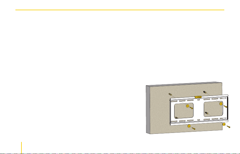
ATTACH THE WALL PLATE TO THE WALL

9Installation Instructions
5. Check the horizontal
orientation by placing the
bubble level on the top
edge of the wall mount.
If the mount isn’t perfectly
horizontal, gently tap
the side that needs
adjustment.
6. Once the wall mount
is straight, tighten the
screws until the mount
secure.

10 Installation Instructions
Drywall and Concrete
Wall Installation
1. In the area where you
want to mount your
screen, use the leveler to
ensure the wall mount is
straight, and mark the
appropriate mount holes
with a pencil.
2. Use a 3/8 in. (10 mm)
drill bit, and drill holes
approximately 2.4 in.
(60 mm) deep into the
wall, and insert the
anchors (J) into the holes.
3. Attach the wall mount to
the wall with screws (I)
and washers (K) until the
wall mount is held in place,
but do not completely
tighten the screws.
4. Check the horizontal
orientation by placing the
bubble level on the top
edge of the wall mount.
If the mount isn’t perfectly
horizontal, gently tap
the side that needs
adjustment.
5. Once the wall mount
is straight, tighten the
screws until the mount
secure.

11Installation Instructions
1. Lift the screen up to the
wall mount, and hang
the screen from the top
hooks of the brackets.
Important!
We recommend
that two people perform
this step.
2. Use the tilt tensions
knobs on both brackets
to adjust the tension on
the tilting mechanism.
MOUNTING THE SCREEN TO THE WALL MOUNT
-10° - +5°

12 Installation Instructions
1. For extra security, align
the locking bar with the
bottom hooks of the
brackets, and slide it in
from the right side behind
the screen. The corner
tab of the locking bar
should face out, away
from the wall.
2. Insert a lock into the hole
at the end of the
locking bar.
USING THE LOCKING BAR

13Installation Instructions
Adjustment screws are
located at the top of
each bracket.
Once your screen is mounted
on the wall mount, use the
included bubble level to check
the horizontal orientation
of your screen. If necessary,
use the included hex key to
turn the adjustment screws
until the bubble is between
the two level lines.
POST-INSTALLATION ADJUSTMENT

14 Safety Warnings
SAFETY WARNINGS
1Do not use this product for any
flat-panel screen device other than
what it is intended for; the exact
specifications, size parameters, and
weight limits are found both on the
product box and in the instruction
manual.
2It is strongly recommended that this
product be installed by a qualified
professional or installation contractor;
Gabor takes no responsibility for any
product damage or personal injury
resulting from mishandling, incorrect
mounting, faulty assembly, or
improper use of this product.
3This product has been designed
specifically for mounting directly
on wooden studs or concrete
walls; depending on wall type and
material, the use of additional
appropriate mounting hardware and/
or accessories such as heavy-duty
anchors may be required.
4The supplied mounting hardware is
not intended for use on metal studs
or cinderblock walls, and may not be
appropriate for old or weak walls;
it is best to consult with a qualified
professional to determine whether
your walls are capable of supporting
this mount.
5This product must always be
mounted directly to center of wooden
wall studs or on a solid concrete
wall to properly support the weight
of the device; the wall may require
reinforcement prior to mounting
(i.e., metal studs, plaster on lath, or
irregular spacing of studs), which
should be determined by a qualified
professional.
6Do not mount this device on structures
that may be affected by vibrations
or noticeable impacts; do not install
near a heater, fireplace. or any other
source of direct heat energy.
7It is recommended that at least
two people perform the installation
process to prevent injury from
mishandling or dropping of the product
and/or flatscreen device; proper safety
gear and tools must be utilized at all
times when installing this product.
8When installing this product, be sure
to refer to the mounting instructions
detailed in this manual; failure to
abide by the mounting instructions
may void the product warranty.
9This product may contain small parts
which can possibly pose a choking
hazard; keep out of reach of children
and pets.
10 When cleaning this product, use only
a mild detergent solution, and quickly
wipe dry with a soft cloth.
11 All images are for illustrative
purposes only.

15Customer Support / Warranty
CUSTOMER SUPPORT
For more information or
to arrange service, visit
www.madebygabor.com
or call Customer Service
at 212-594-2353.
Product warranty is provided by
the Gradus Group.
www.gradusgroup.com
Gabor is a registered trademark
of the Gradus Group.
© 2019 Gradus Group LLC.
All Rights Reserved.
GG4
ONE-YEAR LIMITED WARRANTY:
This GABOR product is warranted to the original purchaser to be free from defects in
materials and workmanship under normal consumer use for a period of one (1) year
from the original purchase date or thirty (30) days after replacement, whichever
occurs later. The warranty provider’s responsibility with respect to this limited
warranty shall be limited solely to repair or replacement, at the provider’s discretion,
of any product that fails during normal use of this product in its intended manner and
in its intended environment. Inoperability of the product or part(s) shall be determined
by the warranty provider. If the product has been discontinued, the warranty provider
reserves the right to replace it with a model of equivalent quality and function.
This warranty does not cover damage or defect caused by misuse, neglect,
accident, alteration, abuse, improper installation or maintenance. EXCEPT
AS PROVIDED HEREIN, THE WARRANTY PROVIDER MAKES NEITHER ANY
EXPRESS WARRANTIES NOR ANY IMPLIED WARRANTIES, INCLUDING BUT
NOT LIMITED TO ANY IMPLIED WARRANY OF MERCHANTABILITY OR FITNESS
FOR A PARTICULAR PURPOSE. This warranty provides you with specific legal
rights, and you may also have additional rights that vary from state to state.
To obtain warranty coverage, contact the Gabor Customer Service Department
to obtain a return merchandise authorization (“RMA”) number, and return the
defective product to Gabor along with the RMA number and proof of purchase.
Shipment of the defective product is at the purchaser’s own risk and expense.

WWW.MADEBYGABOR.COM
This manual suits for next models
1
Table of contents
Other GABOR TV Mount manuals
Popular TV Mount manuals by other brands

Omnimount
Omnimount ELEMENTS 403 FP Product information sheet

Omnimount
Omnimount SW1 instruction manual

Omnimount
Omnimount VB150T instruction manual

VOGELS
VOGELS TM 7655 Series installation guide

New Star
New Star NeoMounts LED-W400BLACK instruction manual

RED ATOM
RED ATOM REDXLFOPEN175P instruction manual