GAI-Tronics TP4512SYN-6 Operating manual

Pub.: 42004-325A
GAI-Tronics Corporation P.O. Box 1060, Reading, PA 19607-1060 USA
610-777-1374 n800-492-1212 nFax: 610-775-6540
GAI-TRONICS CORPORATION
6-Channel Radio
User and Installation Manual
TABLE OF CONTENTS
Confidentiality Notice................................................................................................................1
General Information..................................................................................................................1
Scope of Manual.................................................................................................................................1
Features and Functions......................................................................................................................1
Description.................................................................................................................................1
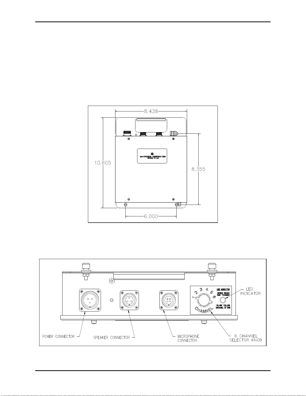
Connectors .........................................................................................................................................2
Power Connector ........................................................................................................................................... 3
Speaker Connector......................................................................................................................................... 3
Microphone Connector .................................................................................................................................. 3
Antenna Connector........................................................................................................................................ 3
Channel Selector Switch....................................................................................................................3
Radio Transceiver Module ................................................................................................................3
Interface PCBA..................................................................................................................................4
Jumper Table................................................................................................................................................. 4
Pot 1.............................................................................................................................................................. 4
Wide Range (110/220 V AC/270 V DC) Power Supply PCBA..........................................................4
Pot 2.............................................................................................................................................................. 4
Surge Filter PCBA.............................................................................................................................4
Optional Standby/Emergency Battery ..............................................................................................4
Installation.................................................................................................................................6
Mounting............................................................................................................................................6
FCC Interference Warning................................................................................................................6
Safe Handling of CMOS Integrated Circuit Devices........................................................................6
Equipment Required..........................................................................................................................7
Test Equipment.............................................................................................................................................. 7
Documentation .............................................................................................................................................. 7
Cable Installation Safety Considerations..........................................................................................8
Surge Protection.................................................................................................................................8
Antenna Connection ..........................................................................................................................9
Power Connections.............................................................................................................................9
Battery Connections.........................................................................................................................10
Microphone Connection...................................................................................................................10

Table of Contents
Pub.: 42004-325A
GAI-TRONICS 6-CHANNEL RADIO
ii
Speaker Connection.........................................................................................................................10
Programming...................................................................................................................................10
Power Supply Adjustment...............................................................................................................10
Speaker Output Adjustment............................................................................................................11
Operation.................................................................................................................................11
Initiating Calls............................................................................................................................................. 11
Receiving Calls............................................................................................................................................ 11
Controls....................................................................................................................................................... 11
Maintenance ............................................................................................................................12
Ordering Replacement Parts...........................................................................................................12
Service and Repair...........................................................................................................................12
Troubleshooting the 6-Channel Radio ............................................................................................12
Fuse Replacement............................................................................................................................13
Battery Replacement........................................................................................................................13
Performance Specifications .....................................................................................................13
Accessories .......................................................................................................................................14
Field Replacement Items..................................................................................................................14

Pub.: 42004-325A
GAI-Tronics Corporation P.O. Box 1060, Reading, PA 19607-1060 USA
610-777-1374 n800-492-1212 nFax: 610-775-6540
6-Channel Radio
User and Installation
Confidentiality Notice
This manual is provided solely as an operational, installation, and maintenance guide and contains
sensitive business and technical information which is confidential and proprietary to GAI-Tronics.
GAI-Tronics retains all intellectual property and other rights in or to the information contained herein,
and such information may only be used in connection with the operation of your GAI-Tronics product or
system. This manual may not be disclosed in any form, in whole or in part, directly or indirectly, to any
third party.
General Information
Scope of Manual
This manual provides descriptive data and service
information for the following models of the
GAI-Tronics 6-Channel Radio:
•TP4512SYN-6 110/220 V ac, 270 V dc
Frequencies programmed by customer
•TP4514SYN-6 120 V ac
Frequencies programmed by customer
•TP4512SYN-6FR 110/220 V ac, 270 V dc
Frequencies programmed at factory
•TP4514SYN-6FR 120 V ac
Frequencies programmed at the factory
Features and Functions
•Easy installation and maintenance
•Portability with integral handle
•Programmable CTCSS and DPL provided as standard
•Heavy-duty industrial power supply and power line filter eliminates the need for external filtering
•Selection of power sources, speakers, and antennas provides system configuration flexibility
•High power receive audio and noise canceling microphone for noisy environments
•Standby/emergency battery option (integral to the chassis) providing continuous operation during
temporary power interruptions
Description
The GAI-Tronics 6-Channel Radio is a stationary-mounted UHF transceiver suited for industrial
complexes, especially in cranes or other mobile equipment. It has a heavy-duty housing and includes a
choice of power sources (270 V dc or 110/220 V ac), microphones, speakers, and antennas. It has a 2-
watt RF output and CTCSS for private communications is selectable.
Figure 1. GAI-Tronics 6-Channel Radio

Page 2of 14
GAI-Tronics 6-Channel Radio Pub.: 42004-325A
f:\standard ioms - current release\42004 instr. manuals\42004-325a.doc
10/00
The radio measures 11.25 W x 14.125 H x 3.00 D. The housing is also a mounting bracket, and includes
and integral handle. The mounting bolts double as support feet when the unit is placed horizontally on a
flat surface such as on a desktop.
The channel selector switch and the power, speaker, and microphone connectors are located on the top of
the unit. The antenna connection is on the underside of the unit and remains easily accessible when the
unit is mounted. Refer to the outline drawings below.
The standard power supply is nominal 120 V ac. There are 110/220 V ac or 270 V dc power supply
options available. Added filtering is standard for the 270 V dc option. The radio transceiver module is
easily replaceable in the field, but must be reprogrammed by a qualified technician.
Connectors
Refer to the figure below for the location of the connectors and channel selector switch.
Figure 2. Outline of 6-Channel Radio
Figure 3. Top View of the 6-Channel Radio

Page 3of 14
GAI-Tronics 6-Channel Radio Pub.: 42004-325A
f:\standard ioms - current release\42004 instr. manuals\42004-325a.doc
10/00
Power Connector
Refer to the Figure 3for the locations of the connectors. The pinout for the power connector is as
follows:
Pin No. Function
ASpare
BLine hot (positive)
CLine neutral (negative)
Speaker Connector
The speaker connector pinout is as follows:
Pin No. Function
ACommon
B8-ohm speaker
C16-ohm speaker
Microphone Connector
The microphone pinout is as follows:
Pin No. Function
AMic high
BPTT (Transmit key)
CMic Lo
D15 V dc power
Antenna Connector
The antenna connector is a coax cable connector.
Channel Selector Switch
The channel selector switch on the top of the unit provides the capability to easily select among the six
labeled channels. In addition, a lighted LED provides indication of the state of the radio.
Radio Transceiver Module
The radio transceiver module is 450 MHz and the six channel frequencies may be factory-programmed to
the customer’s specifications. The frequencies can be programmed in steps of 12.5 kHz. The radio
transceiver can also be programmed for CTCSS.
Note: When the radio transceiver module is programmed for CTCSS or DPL it can only communicate
with other radios that have the same CTCSS or DPL programming.

Page 4of 14
GAI-Tronics 6-Channel Radio Pub.: 42004-325A
f:\standard ioms - current release\42004 instr. manuals\42004-325a.doc
10/00
Interface PCBA
The Interface PCBA provided as standard equipment maintains regulation per a wide range of input
voltages, and in addition to the internal protection, it is further protected from transients on the external
power source by the optional surge filter PCBA. The power supply provides regulated 12.5 V dc to the
radio circuits. It contains three jumper settings, which can be configured in accordance with the table
below.
Jumper Table
Jumper
Name Function Position Default
(as shipped)
JU1 Receive Audio Level Select Out = High level
In = Low level attenuated 15 dB Out
JU2 Speaker Power Amp Enable 1-2 = Enabled by Carrier Detect
2-3 = Always enabled 1-2
JU3 Microphone Bias In = Supply bias power to Mic
Out = No bias In
Pot 1
Pot 1 is used to adjust the speaker level. Refer to Figure 4on page 5for the location of the pot. Refer to
the Installation section for instructions for speaker output adjustment.
Wide Range (110/220 V AC/270 V DC) Power Supply PCBA
This switch-mode power supply features high-efficiency operation over an 85 to 300 V ac or dc input
range. The output is adjustable to provide proper float charging voltage to the optional standby battery.
Pot 2
The power supply PCBA contains a pot adjustment, Pot 2. It is used to adjust the charging current into
the optional standby/emergency battery. Refer to Figure 4on page 5for the location of the pot. Refer to
Installation section for instructions for the charging current adjustment.
Surge Filter PCBA
This module provides additional power input filtering for noisy industrial 270 V dc power. It is standard
only on the TP4512SYN-6 and the TP4512SYN-6FR.
Optional Standby/Emergency Battery
Each radio model is designed to operate with a rechargable battery.
When installed, the standby/emergency battery supplies power for up to 15 minutes during maximum
power drain, and longer at the average power drain. The GAI-Tronics 40201-004 battery is sold
separately.

Page 5of 14
GAI-Tronics 6-Channel Radio Pub.: 42004-325A
f:\standard ioms - current release\42004 instr. manuals\42004-325a.doc
10/00
For locations of internal components, refer to the diagram shown below:
Figure 4. Internal Components of the 6-Channel Radio

Page 6of 14
GAI-Tronics 6-Channel Radio Pub.: 42004-325A
f:\standard ioms - current release\42004 instr. manuals\42004-325a.doc
10/00
Installation
Mounting
The radio can be placed horizontally on a desk or mounted vertically on a wall. To wall mount the radio,
remove the four bolts/support feet from the back of the housing. Mark the position of the housing, and
reinstall the bolts through the housing to a base plate or other suitable support.
FCC Interference Warning
The FCC requires that manuals pertaining to Class A and Class B computing devices must contain
warnings about possible interference with local residential radio and TV reception. This warning reads as
follows:
Note: This equipment has been tested and found to comply with the limits for a Class A digital device,
pursuant to Part 15 of the FCC Rules. These limits are designed to provide reasonable protection against
harmful interference when the equipment is operated in a commercial environment.
This equipment generates, uses, and can radiate radio frequency energy and, if not installed and used in
accordance with the instruction manual, may cause harmful interference to radio communications.
Operation of this equipment in a residential area is likely to cause harmful interference in which case the
user will be required to correct the interference at his own expense.
Safe Handling of CMOS Integrated Circuit Devices
Many of the integrated circuit devices used in communications equipment are of the Complementary
Metal Oxide Semiconductor (CMOS) type. Because of their high open circuit impedance, CMOS
integrated circuits are vulnerable to damage from static charges. Care must be taken handling, shipping,
and servicing them and the assemblies in which they are used.
Even though protection devices are provided in CMOS integrated circuit inputs, the protection is effective
only against overvoltage in the hundreds of volts range such as is encountered in an operating system. In
a system, circuit elements distribute static charges and load the CMOS circuits, decreasing the chance of
damage. However, CMOS circuits can be damaged by improper handling of the modules, even in a
system.
Figure 5. Sample Installation Diagram

Page 7of 14
GAI-Tronics 6-Channel Radio Pub.: 42004-325A
f:\standard ioms - current release\42004 instr. manuals\42004-325a.doc
10/00
To avoid damage to circuits, observe the following handling, shipping, and servicing precautions:
1. Prior to and while servicing a circuit module, particularly after moving within the service area,
momentarily touch both hands to a bare metal, earth-grounded surface. This will discharge any static
charge which may have accumulated on the person doing the servicing.
Note: Wearing a conductive wrist strap will minimize static build-up during servicing.
2. Whenever possible, avoid touching any electrically conductive parts of the circuit module with your
hands.
3. Power down the unit before installing or removing the circuit module.
4. When servicing a circuit module, avoid carpeted areas, dry environments, and certain types of
clothing (silk, nylon, etc.) because they contribute to static build-up. Similarly, disconnect the test
probe prior to removing the ground lead.
5. All electrically powered test equipment should be grounded. Apply the ground lead from the test
equipment to the circuit module before connecting the test probe.
6. If a circuit module is removed from the system, it is desirable to lay it on a conductive surface (such
as a sheet of aluminum foil) which is connected to ground through 100K of resistance.
7. When soldering, be sure the soldering iron is grounded with a grounded tip.
8. Prior to connecting jumpers, replacing circuit components, or touching CMOS pins (if this becomes
necessary in the replacement of an integrated circuit device), be sure to discharge any static build-up
as described in procedure 1. Since voltage differences can exist across the human body, it is
recommended that only one hand be used if it is necessary to touch pins on the CMOS device and
associated board wiring.
9. When replacing a CMOS integrated circuit device, leave the device in its conductive rail container or
conductive foam until it is to be inserted into the printed circuit module.
10. All low impedance test equipment (such as pulse generators, etc.) should be connected to CMOS
device inputs after power is applied to the CMOS circuitry. Similarly, such low impedance
equipment should be disconnected before power is turned off.
11. Replacement modules shipped separately from the factory will be packaged in a conductive material.
Any modules being transported from one area to another should be wrapped in a similar material
(aluminum foil may be used). Never use non-conductive material for packaging these modules.
Equipment Required
Test Equipment
•RF service monitor
•AC voltmeter with dB ranges for measuring audio levels
•#1 Phillips screwdriver
•1/8-inch flat blade screwdriver
Documentation
•these installation instructions
•the manual for the radio transceiver module, Pub. DTX-MRM

Page 8of 14
GAI-Tronics 6-Channel Radio Pub.: 42004-325A
f:\standard ioms - current release\42004 instr. manuals\42004-325a.doc
10/00
Cable Installation Safety Considerations
Interconnecting, communications, and Class 2 dc power cables should be separated from electrical light
or other Class I circuits by at least 2 inches. The exception is where Class I wiring or power circuits are
run in a raceway, or are metal-sheathed or metal-clad, or are permanently separated from the conductors
of the other circuitry by a continuous and firmly fixed nonconductor such as porcelain tubes or flexible
tubing in addition to the insulation on the wire. Communications cables and in-building wiring should be
listed and marked for the purpose according to NEC Article 800.
Surge Protection
The Model TP4514SYN-6 6-Channel Radio (120 V ac) incorporates standard agency-approved surge
protection. The power line fuse on the power supply module must be replaced with the same type fuse to
maintain agency approval and safety protection.
Additional surge protection is available on the TP4512SYN-6 module with additional safety fusing.
These fuses must also be replaced with the same type to maintain agency approval and safety protection.
See the Field Replacement Items section.
Figure 6. TP4512SYN-6 Connection Diagram

Page 9of 14
GAI-Tronics 6-Channel Radio Pub.: 42004-325A
f:\standard ioms - current release\42004 instr. manuals\42004-325a.doc
10/00
Figure 7. TP4514SYN-6 Connection Diagram
Antenna Connection
Select a Model CN3614 or similar antenna. Connect the antenna to the underside of the radio unit using
the 25-foot coax antenna cable. Refer to Figure 6and Figure 7for the respective models above.
Select an area for antenna mounting which gives the antenna an unobstructed view of the surrounding
area. Without proper line of sight to other antenna(s), TX and RX may be hindered. Antennas should be
mounted at least 3 feet from I-beams and metal bulkheads.
Note: Check the antenna with a watt meter for proper standing wave ratio (SWR).
Power Connections
The power connections for all voltage options connect to the same MS connector on the top end of the
chassis. The power cord is not included. Refer to Figure 6and Figure 7for the respective models above.
CAUTION
Connect the power cable to the correct power source. Follow all the appropriate National Electric
Code as well as local county and city electric codes.
•The black wire (pin B) is hot in the case of 110/220 V ac (on Model TP4512SYN-6) and positive for
270 V dc (on Model TP4514SYN-6).
•The white wire (pin C) is neutral or negative.

Page 10 of 14
GAI-Tronics 6-Channel Radio Pub.: 42004-325A
f:\standard ioms - current release\42004 instr. manuals\42004-325a.doc
10/00
Battery Connections
Install the GAI-Tronics 40201-004 Battery as follows. Refer to Figure 4on page 5.
1. Loosen the mounting screws on the left of the 14910-007 battery bracket and lift it out of the key hole
slot. Slide the battery into place. Replace the bracket and tighten the bracket screws.
2. The battery wire connections are parked on terminals TP1 and TP2 on the power supply board.
3. Unplug the black wire from the power supply board and slide onto (-) negative terminal of the
battery.
4. Unplug red wire from the power supply board and slide onto (+) positive terminal of the battery.
Note: If the battery is already charged a small spark may occur when connecting the red wire. This
is normal.
Microphone Connection
Select a Model MI2895 or similar microphone. Install the microphone by plugging it in using the
appropriate connector on the top of the radio.
Speaker Connection
Select a Model 651301/102 or similar cast speaker. Install the cast speaker by plugging it into the
appropriate connector on the top of the radio.
Programming
The radio transceiver module contains programmable features, such as CTCSS and frequency selection,
that are factory-set to the customer’s specifications. Refer to the associated manual, Ritron Models STX-
150 and DTX-450 Programmable FM Transceiver Modules, Publication No. DTX-MRM.
Any changes should be made by a qualified technician. A software programming kit, available from the
original manufacturer is required (Ritron RPT-PCPK-3.0).
Power Supply Adjustment
The power supply PCBA is factory-adjusted for a float voltage of 13.8 V dc at 11.5 mA charging current
into the optional standby/emergency battery. The charging current can be adjusted using Pot 2 on the
power supply PCBA. Refer to Figure 4on page 5for location of Pot 2. If field adjustment becomes
necessary, the procedure is as follows:
1. Disconnect the battery terminals and substitute a 1200 ohm, 5% resistor connected across the
‘fast-on’ terminals that are disconnected from the battery.
2. Measure across the resistor, and adjust the float level, Pot 2, for 13.8 +0.1 V dc.
3. Disconnect the load resistor and re-connect the leads of the battery.

Page 11 of 14
GAI-Tronics 6-Channel Radio Pub.: 42004-325A
f:\standard ioms - current release\42004 instr. manuals\42004-325a.doc
10/00
Speaker Output Adjustment
The speaker output volume is adjustable using Pot 1 on the interface PCBA. Refer to Figure 4on page 5
for the location of Pot 1. The adjustment procedure is as follows:
1. With the speaker in place, initiate a radio conversation with a second radio user.
2. Adjust Pot 1 for the desired maximum speaker volume.
Operation
Use the microphone to operate the radio in a standard push-to-talk/release-to-listen mode. Choose among
the six channels by rotating the channel selector switch.
Keep transmissions short to avoid tying up the channel. Continuous transmissions longer than 30 seconds
will be terminated by a built-in transmit limit timer (TOT).
Note: This setting can be factory adjusted.
Note that units programmed with the CTCSS or DPL can only carry on two-way communications with
units which have identical CTCSS or DPL programming. Refer to the transceiver module manual, Ritron
Pub. DTX-MRM, for details.
Initiating Calls
1. To initiate a call, press the microphone button. Always allow a short delay before speaking to allow
time for the radio channel to be established.
2. Speak directly into the microphone held approximately 1/2 inch from the mouth. The microphone
button must be held down while talking to the radio user and released to listen.
3. When the transmission is completed, the radio returns to the receive mode.
Receiving Calls
When power is applied, the radio is in the receive mode, allowing receive audio to be heard through the
speaker. The radio is always in receive mode unless the user presses the microphone button. To reply to
a call, wait until the caller has finished speaking; then press the microphone button and reply.
Controls
The rotary frequency switch on the top of the unit selects the radio channel. The multi-color LED
indicates the radio channel status.
•Green: Indicates power is on/idle condition
•Flashing yellow: Indicates channel activity (in use)
•Red: Indicates transmitter on (PTT active)

Page 12 of 14
GAI-Tronics 6-Channel Radio Pub.: 42004-325A
f:\standard ioms - current release\42004 instr. manuals\42004-325a.doc
10/00
Maintenance
Ordering Replacement Parts
When ordering replacement parts or requesting equipment information, the complete identification
number should be included. This applies to all components, kits, and chassis. If the component part
number is not known, the order should include the number of the chassis or kit of which it is a part and
sufficient description of the desired component to identify it. Order parts from:
Customer Service
GAI-Tronics Corporation
400 E. Wyomissing Ave.
Mohnton, PA 19540
US: 800-492-1212
Outside US: 610-777-1374
Service and Repair
Inoperative or malfunctioning equipment should be returned to the factory for repair. Please call 1-800-
492-1212 (select option #2 from the menu) to obtain a Return Authorization number, published repair
prices, and shipping instructions.
Note:A purchase order or credit card number will be required prior to processing non-warranty repairs.
Troubleshooting the 6-Channel Radio
The following is a list of potential problems you may encounter and possible solutions.
Problem Possible Solution
The radio does not
transmit. 1. Check to determine if logic low is reaching the radio via P1 pin 6.
2. Check to determine if power and ground are reaching the radio via P1 pin
5 and pin 9.
Radio is getting power,
ground, and PTT, but still
does not transmit.
Replace radio module. Replacement and any necessary reprogramming must
be made by a licensed technician.
There is no receive audio. 1. Check to determine if voltage on U3 pin 8 is the same as U3 pin 7 (audio
enable function).
2. Using a high impedance ac voltmeter, check for audio signal at P1 pin 10
and U2 pin 7.
3. Check for audio signal at TB2 (speaker terminals).

Page 13 of 14
GAI-Tronics 6-Channel Radio Pub.: 42004-325A
f:\standard ioms - current release\42004 instr. manuals\42004-325a.doc
10/00
Fuse Replacement
CAUTION
For continued safe operation, replace fuses with the same type (See Field Replacement Items):
•Power supply PCBA fuse F1 is a Bussman C515S 1.25A SB 2AG
•Power supply PCBA fuse F2 is a Bussman Slo-Blo GMA 5A 250 V
•Surge filter PCBA fuses F4 and F5 is a Bussman Slo-Blo GMA 2A
Battery Replacement
The optional standby/emergency battery is designed to have a shelf life of approximately two years, but
battery life may be reduced depending on use. The battery is automatically re-charged during normal
radio usage. If the battery fails to operate the radio during a brief power interruption, the battery may
need to be replaced.
Replace the battery (Part No. 40201-004) as follows:
1. Disconnect the cable connectors at the top of the battery, by sliding them off.
2. Remove the two screws on the left of the battery mounting bracket.
3. Slide the bracket to the left and lift it out of the key hole slot.
4. Reverse the process to install the new battery.
Performance Specifications
Color................................................................................................................................................Black
Construction.................................................................................................Dust-resistant steel enclosure
Physical Size ...................................................................................14.125 H x 11.250 W x 3.00 D inches
Weight.............................................................................................................................................10 lbs.
Temperature Range............................................................................................................ -30ºC to +60ºC
Humidity...................................................................................................................90% non-condensing
270 V dc option
Supply Voltage Range .............................................................200 to 350 V dc range, (270 V dc nominal)
Power Consumed.........................................................................................8 W Standby/30 W maximum
Supply Voltage Filtering.................................................................................. Two stage LC, RES, MOV
110/220 V ac option
Supply Voltage Range ........................................ 85 to 260 V ac range, (50/60 Hz; 110/220 V ac nominal)
Power Consumed.........................................................................................8 W Standby/30 W maximum
Channel Frequencies 1 through 6........................................................................As specified by customer
Speaker Amplifier......................................................................................8 watt maximum into 8/16 ohm
450 MHz Radio Transceiver ................................................................See Ritron Publication DTX-MRM
Microphone.......................................................................... MI2895 dynamic, amplified, noise canceling
Speaker..............................................................651301/102 Cast aluminum, 16-ohm with volume control
Antennas ..................................................................................................CN3614 1/4 wave whip antenna
Connections............................................................................................................. MS Series connectors
Standby/Emergency Battery Option.............................................15 minutes under maximum power drain
longer with average current drain

Page 14 of 14
GAI-Tronics 6-Channel Radio Pub.: 42004-325A
f:\standard ioms - current release\42004 instr. manuals\42004-325a.doc
10/00
Model Numbers
TP4512SYN-6..........................................110/220 V ac, 270 V dc; Frequencies programmed by customer
TP4514SYN-6.................................................. 120 V ac, 12 V dc; Frequencies programmed by customer
TP4512SYN-6FR.........................................110/220 V ac, 270 V dc; Frequencies programmed at factory
TP4514SYN-6FR............................................120 V ac, 12 V dc; Frequencies programmed at the factory
Note: Customers are to supply frequencies to GAI-Tronics at the time of order
Accessories
Description Part No.
Microphone, Noise Canceling MI2895
Cast Aluminum Speaker 651301/102
Antenna with 25-foot Coax Cable and Connector CN3614
UHF Ground Plate CH3272
6-Channel Radio to GAI-Tronics Page/Party® Coupler 1931888-3011
Ritron DTX Radio Programming Kit RPT-PCPK-3.0
Ritron DTX Radio Programming Manual DTX-MRM
Battery, Yuasa NP 1.2-12 12V, 1.2AH sealed rechargeable, lead-acid 40201-004
Field Replacement Items
Description Part No.
Fuse F1 (Power Supply PCBA) Bussman C515S 1.25A SB 2AG 4612-23015-25
Fuse F2 (Power Supply PCBA) Bussman SB GMA 5 amp 250 V 51808-007
Fuse F4 and F5 (Surge Filter PCBA) Bussman SB GMA 2 amp 51809-008
Protective Cap, 7/8-inch MC3761
Protective Cap, 1-1/8 inches MC3762
This manual suits for next models
3
Table of contents
Other GAI-Tronics Radio manuals