GAL MOVFE 2500 User manual

2500 - 3069
1 (888) 425-2262
2500 - 3069
ELECTRICAL

Rev.1-10/20
I

II
TABLE OF CONTENTS
Foreword I
Comments & Important Notes I
Table of Contents II
OVERVIEW 1
ELECTRICAL COMPONENTS OF 02VFE25 4
1. Toggle switches 4
2. LED Indicators 5
3. Optical Sensors for Harmonic Model 6
4. Hall-effect Sensors for Linear Model 6
5. Inputs 7
6. Outputs 7
7. Additional I/O Board 8
8. Encoder module 8
9. Encoder 8
10.Learn Door Width LED 9
11.CAN bus module 9
12.Infrared Detector Edges Connection Ports 9
13.Parameter Unit 11
INITIAL SETUP 14
1. Turn Power ON 14
2. Motor Direction 14
3. Encoder Direction 14
5. Learn The door width 16
5.1 Door is between DOL and DCL 16
5.2 Door is fully Opened 16
5.3 Door is fully Closed 16
6. Set the operation source 17
PARAMETER UNIT 18
1. How to change parameters 18
2. How to read (copy) from a drive 18
3. How to write (download) to a drive 18
4. How to verify encoder direction 18
5. How to learn the door width 18
6. Default parameters 19
Voltage, Current, Frequency 20
II

III
Inputs and Outputs Monitoring 20
Faults 21
Counters 21
User List 22
User parameters 22
Motor and Encoder 22
Door parameters 23
Open parameters 23
Digital I/O parameters 24
Direction 25
Communication 26
Maximum Close Speed 26
Maximum Close Force 26
ECI Defaults 27
Harmonic 27
Linear Straight 27
Linear Geared 27
Display Groups 28
Code Distance (CD) Closing Time Display 28
CD Closing Time 28
DOL ÎDCL Time 28
CD Opening Time 28
DCL ÎDOL Time 28
LED Indicators 28
SPEED PROFILES OF THE VFE2500 29
Normal Door 29
Heavy Door 30
Narrow Door 31
SENSORS SETTING 32
Hall-effect sensors setting for linear door operator 32
Optical sensors setting for harmonic door operator 32
PARAMETERS LIST FOR USERS 33
Group 0: User parameters 33
Group 1: Motor & Encoder parameters 33
Group 2: Door parameters 34
Group 3: Open direction parameters 35
Group 4: Close direction parameters 41
Group 5: Digital I/O parameters 46
Group 6: Protection parameters 47
Group 7: Communication parameters 48
Display Parameters 48
WIRING DIGRAMS 51
III

IV
SUPPORTIVE GRAPHS 52
V/F curve for Normal door 52
V/F curve for Heavy door 52
V/F curve for Narrow door 53
DC Injection 53
Stall Reverse detection 54
Frequency Failure detection 54
Infrared Detector Edges detection 54
Edges Timeout relay and Buzzer timing 55
Edges Timeout relay and Buzzer mode 55
Interaction between Re-open and Edges Timeout relay 56
FAULTS LIST 57
FAULTS RESET HANDLING FLOWCHART 61
CLUTCH ENGAGED DISTANCE SETUP 62
DOOR STALL FORCE MEASUREMENT 63
CODE DISTANCE CLOSING TIME SETUP 64
MINIMUM CLOSING TIME (ECI REFERENTIAL VALUE) 65
CHECKING PROCEDURE FOR THE CLOSING CODE TIMES 66
INTERFACING BETWEEN ECI CERTIFIED LIGHT CURTAIN AND VFE2500 67
Understanding the RE-OPEN relay 67
How to interface between the Infrared Detector Edges and VFE2500 67
Test the Infrared Detector Edges 67
If the Detector Edges function does not work 68
If the Detector Edges have intermittent problems 68
Infrared Detector Edges connection 69
INFRARED DETECTOR EDGES APPLICATION FLOWCHART 70
OPTIONAL APPLICATIONS
HEAVIER DOOR 71
NARROWER DOOR 72
NARROWER DOOR APPLICATION FLOWCHART 73
NUDGING 74
NUDGING APPLICATION FLOWCHART 75
SERIAL COMMUNICATION 76
PARTS LIST 77
NOTES & COPYRIGHT 85
IV

1
OVERVIEW:
The general block diagram of the VFE2500 is in the illustration below:
The VFE2500 door operator has the following features:
DOUBLE FEEDBACK SYSTEM FOR SMOOTH PERFORMANCE:
xDistance and velocity closed-loop system
xOnce the door-width is learned, VFE2500 will optimize control of the elevator door(s)
xParameters sets are provided to maximize the performance of the system
Following is a simplified control diagram of the VFE2500.
TERMINAL INPUTS
CAN BUS
KEYPAD
OR
RS 485
VFE2500
DRIVE
QUADRATURE
ENCODER
INFRARED
DETECTOR
EDGES
(OPTIONAL)
TRANSMITTER
RECEIVER
3PH
INDUCTION
MOTOR
230VAC
POWER
SUPPLY
OPTICAL
SENSORS
FOR
HARMONIC
OPERATOR
HALL-EFFECT SENSORS
FOR LINEAR OPERATOR
SIGNALS TRANSFER
SECTION
FOR LINEAR OPERATOR
ADDITIONAL I/O
FOR HEAVY, NARROW DOORS
AND NUDGING APPLICATION
CURRENT
LIMITER
3 PHASE
AC MOTOR
CURRENT
FEEDBACK
SPEED
CONVERSION
&
FEEDBACK
POSITION
CONVERSION
&
FEEDBACK
¦
---
QUADRATURE
ENCODER
KEYPAD
OR
RS 485
PWM
PID
CONTROLLER
TERMINAL
INPUTS
CAN BUS ¦ ¦
POSITION
CONTROL
SPEED
CONTROL
IGBT
SWITCHING
1

2
SAFETY STANDARDS:
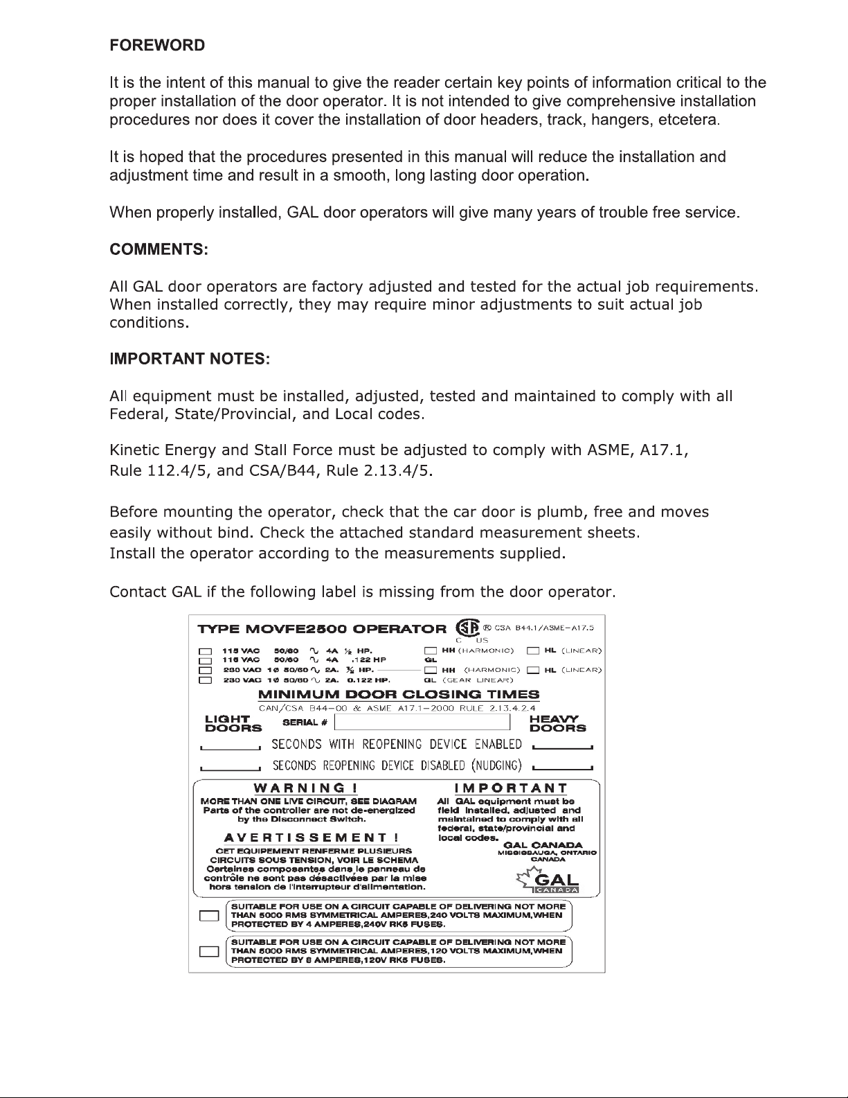
xCSA Certified. B44.1/ASME- A17.5
xComplies with the following CE and IEEE safety standards of
EN61000-4-2, EN61000-4-3 EN61000-4-4, EN61000-4-5, EN61000-4-6, EN61000-4-8,
and IEEE STD C62.45-1992
xEMC conformity report is available
A POWERFUL SYSTEM:
x230VAC and 115VAC power supply versions are available
xVariable voltage, variable frequency (VVVF) drive
xA ½ HP AC motor is used to accommodate for most of door loads, friction, and wind pressure
HARMONIC AND LINEAR MODELS ARE AVAILABLE:
xThree models of VFE2500 are currently available:
¾VFE2500-HH : Heavy duty Harmonic model
¾VFE2500-GL : Light duty Linear model
¾VFE2500-HL : Heavy duty Linear model
NON-CONTACT SENSORS:
xOptical sensors and Hall-effect sensors for final limits, door protection monitor, and narrower
door limit.
CONVENIENCE INDICATORS:
xLight Emitting Diodes (LEDs) on the main board are used to indicate status of all important
functions:
Door open, close, nudging, heavier, narrower input signals,
Door open, and close directions,
Open, and close slowdown,
Obstruction detection signal,
Stall reverse,
Frequency failure,
DOL, DCL, AUX (Narrower door), and DPM (Door Protection Monitor)* output signals,
Door-width learning completion.
UNIVERSAL INPUTS AND OUTPUTS:
xUniversal inputs accept control signals in form of contacts or signal voltages;
from 24-230V AC or DC.
xOutput contacts, rated at 10Amp, 230VAC, include:
Door Close Limit (DCL),
Door Open Limit (DOL),
Re-Open (RE-OPEN),
Door Protection Monitor (DPM),
Auxiliary/Narrower Door (AUX),
Edges Timeout (ET)
xAll input modules, output relays, and connectors are pluggable for easy replacement.
KEYPAD (PARAMETER UNIT):
xKeypad programming with LCD display is available to adjust, monitor, copy, change
parameters, upload parameter sets, and to learn the door width distances.
xDefault parameter sets are ready for all ECI operator models.
xDifferent parameter sets for heavier door and narrower door are available for proper
adjustments to comply with codes.
xThe ability to copy (read) and download (write) parameter sets enables reduced setting time
on similar door operators.
2

3
TOGGLE SWITCHES FOR MANUAL TESTING:
xToggle switches are provided for manual operation, diagnostics, and operational verification
regardless of the control wiring to the elevator controller
OVER-TORQUE AND OVER-SPEED DETECTIONS:
xOver-torque and over-speed detection and restriction are parameterized for easy adjustment
to comply with codes
PLUG-AND-PLAY INFRARED DETECTOR EDGES:
xBoth NPN and PNP infrared detector edges can be connected directly to the VFE2500
simplifying electrical wiring and eliminating the need for an extra power supply
SPECIAL FEATURES ADDED:
xCombined VVVF drive and main board makes the VFE2500 drive easily interchangeable from
one model or job to another
xAdditional I/O for special applications of:
Heavier door, Narrower door, Detector edges timeout for Nudging application, Buzzer output
for alarm before Nudging speed is applied
RELIABLE AND HIGH RESOLUTION FEEDBACK:
xHigh resolution encoder and galvanic isolation techniques are used to deliver smooth, and
reliable operation.
xHardware and software encoder loss detections are employed to prevent run-away conditions
that could otherwise result in a closed-loop control system. This combination of hardware and
software provides an ultimate protection for human life
SERIAL COMMUNICATION TO VFE2500:
xCAN (Controlled Area Network) or other communication protocols can be used to communicate
with VFE2500 serially.
xCAN bus counter and analyzer are built in to monitor the CAN bus activities.
TROUBLESHOOTING ASSISTANCE DISPLAY:
xThe Faults display will explain to users the possible causes and shows the remedies for each
fault code.
MINIMUM CODE DISTANCE CLOSING TIME TABLES:
xThe minimum code distance closing time tables are available on the LCD keypad.
ACTUAL DISPLAY OF THE CLOSING TIME:
xThe actual code distance of the closing time is displayed to assist users in complying with
codes.
AUTO FALLBACK TO SLOW MODE IF SENSORS OR ENCODER FAIL:
xIf DOL, DCL, AUX, or DPM sensor fails, or if the encoder fails, the VFE2500 door operator will
continue to operate in slow scanning mode until repairs are completed
*: Door Protection Monitor is used in the Fault Monitor, which is a door lock and gate switch
protection device. Its purpose is to meet the ASME A17.1 RULE 210.15 and CAN/CSA-B44-M90
RULE 3.12.1.5. The Fault Monitor device can be purchased separately through ECI.
3

4
ELECTRICAL COMPONENTS OF THE VFE2500:
1. Toggle switches:
Order
No. Label Meaning Remarks
1 RUN/SETUP Run or Cam Setup
RUN:
The RUN position is for normal operation.
SETUP:
The SETUP position allows users to adjust the optical
cams of the Harmonic model, or the hall-effect sensors
of the Linear model. These are DOL, AUX, DPM, and
DCL sensors . Crucial parameters can only be adjusted
in STOP mode. The SETUP position will put the drive
into the STOP mode, and no power will be delivered to
the motor.
2 AUTO/MAN. Auto or Manual
AUTO:
The AUTO position is for normal operation.
MAN.:
The MAN. position allows opening and closing the door
by means of the OPEN/CLOSE switch.
3 CLOSE/OPEN Close or Open
When the AUTO/MAN. switch is in the MAN. position, if
the CLOSE/OPEN switch is pressed in the OPEN or
CLOSE positions, it will Open or Close the door
respectively.
4 NUDG. Nudging
NUDG. switch allows closing the door at a reduced
speed (Nudging speed). To test the Nudging speed in
Manual mode, the AUTO/MAN. switch must be in the
MAN. position and the CLOSE/OPEN and NUDG.
switches must be pressed to the CLOSE and NUDG.
positions.
5 NARROW Narrower Door
When the AUTO/MAN. switch is in the MAN. position, if
the NARROW switch is pressed in the NARROW position,
it will work in conjunction with the OPEN/CLOSE, and
NUDG. switches to Open, Close, or Nudge the door.
6 HEAVY/RESET
Heavier Door or
Reset
HEAVY:
When the AUTO/MAN. switch is in the MAN. position, if
the HEAVY/RESET switch is pressed in the HEAVY
position, it will work in conjunction with the
OPEN/CLOSE, NUDG. switches to Open, Close, or Nudge
5(6(7
The RESET position allows manual reset of faults of the
drive, if faults have occurred. Otherwise, pressing the
RESET side has no effect.
Six toggle switches are provided to run the door operator in
manual mode. However, users can also use these switches to
troubleshoot and verify the operation.
the heavier door.
4

5
2. LED indicators:
A red LED is provided on each of the input modules (Open, Close, or Nudge). Heavy and Narrow
inputs are optional and require an additional I/O board, which will be provided on request to carry
out the Heavier and Narrower door functions.
Note that if the input signals voltage is 60V or less, the jumpers on each input module must be removed.
There are 20 more LEDs, on the main board, to indicate the completion of the door width learning,
the directions, the final limit positions, nudging, holding, dynamic slowdown distances, input signals,
output signals, and voltage levels. The illustration below identifies those LEDs.
5

6
3. Optical Sensors for Harmonic Model:
For the harmonic model, there are 4 optical cams to set the final limits, door protection monitor, and
an AUX. cam for the narrower door. The Optical cam board, 2500-3056, carries the optical sensors, and
the table below describes the functions of those sensors.
4. Hall-effect Sensors for Linear Model:
For the linear model, there are 4 hall-effect sensors to set the final limits, door protection monitor,
and an AUX. sensor for the narrower door. These hall-effect sensors have the same functions as in
the harmonic operator, as shown in the table above. They are connected to the signals transfer board
and arranged as follows:
Number
on
Figure
Label Remarks
1 DOL
Door Open Limit. The VFE2500 utilizes
the DOL limit signal for door width
learning. After the door width learning
process is completed, VFE2500 utilizes
the DOL limit as HOME position
whenever power is restored after an
interrupt.
2 AUX
NARROWER
Set Par. 199=0 to use the
AUX/NARROWER sensor as the DOL
input of the narrower door.
Set par. 199 = 1 to deselect the
AUX/NARROWER sensor.
3 DPM
DPM: Door Protection Monitor. The
DPM cam triggers the DPM Relay and
activates ½ inch before the Gate
switch makes.
4 DCL
Door Close Limit. The VFE2500 utilizes
the DCL limit signal for door width
learning. After the door width learning
process is completed, VFE2500 also
utilizes the DCL limit as HOME position
whenever power is restored after an
interrupt.
6

7
5. Inputs:
6. Outputs:
Four relays are provided to output DPM, RE-OPEN, DOL, and DCL signals to the elevator controller
in the form of contacts. The relay contacts are rated at 10Amp, 250VAC maximum and 100mA,
12VAC minimum.
Label Meaning Remarks
DCL Door Close
Limit Door Close Limit
DOL Door Open
Limit Door Open Limit
REOPEN Re-open
This output is used to flag the elevator
controller that the door(s) need to be
reopened. The reopen output DOES NOT
reopen the door directly. The signal to reopen
the door(s) must come from the elevator
controller. Re-open relay is triggered by any
one of the following detections:
- Stall Reverse; controlled by Par. 148.
- Frequency Failure; controlled by Par. 136.
- Detector Edges; controlled by Par. 202,
SW8, and Enable IC U5.
DPM
Door
Protection
Monitor
DPM is designed to work with the Fault
Monitor (FM). FM is a patented door lock and
gate switch protection device. Its purpose is
to meet the ASME A17.1 RULE 210.15 and
CAN/CSA-B44-M90 RULE 3.12.1.5. The
setting position of DPM is ½ inch before the
gate switch makes.
Three input modules are provided to receive OPEN, CLOSE,
and NUDGE commands from the elevator controller. These
universal input modules receive control signals either in
form of contacts or signal voltages; from 24-230V AC o
r
DC. Jumpers on the input modules must be removed if the
input signal voltage is 60V or less. LEDs of the input
modules draw currents from the elevator controller, not
from the VFE2500. Therefore, when these LEDs are lit, they
indicate that the elevator controller has sent commands.
In automatic mode, the VFE2500 will only accept input
signals from the elevator controller. In other words, open,
close or, (nudge + close) LEDs must be on to have the doo
r
operator open, close, and nudge respectively.
7

8
7. Additional I/O Board:
8. Encoder card:
9. Encoder:
Additional I/O board, 2500-3055, is optional. If used, this
board will be connected to the connector J7 of the main board
2500-3050. The additional features of this board are:
- Inputs for the Heavier, and Narrower doors.
Elevator controller must provide command signals
to the Heavy and Narrow inputs to use the functions of
the parameters sets of the Heavier and Narrower doors.
Set Par. 199 = 0 if Narrower door is used.
-Edges Timeout: Once the infrared detector edge is
obstructed, and after a delay set by Par. 197, the
Edges Timeout relay will be activated and held for
an interval of time set by Par. 206. Should the
edges timeout relay be used for Nudging application,
it must be subject to the elevator fire service codes.
- DOL of the narrower door is selectable between the
Regular output DOL on the main board or the
AUX/NARROWER output on the Additional I/O board.
Set Par. 204 = 1 if only the regular DOL output is used.
Set Par. 204 = 0 if both the AUX/NARROWER output
and regular DOL output are used.
- AUX2 relay is provided as a spare output and is controlled
by Par. 68. If the door position is less than the value
set in Par. 68, the AUX2 relay will be activated.
- Buzzer: once the infrared detector edge is obstructed, and
after a delay set by Par. 198, the output of the Buzzer will
be activated. Buzzer operation is controlled by Par. 205.
Par. 205 = 0 : Disable
Par. 205 = 1 : Enable in Continuous mode
Par. 205 = 2 : Enable in Pulsating mode
The Buzzer volume control is on the board. Turn the Pot. R3
clockwise for louder sound.
The optical galvanic isolation encoder card is a means to interface between the
encoder and The MCU (Micro Controller Unit). This total isolation helps enhance
the reliability and safety of the feedback system.
RJ12 mating gold-plated connectors are also used to maximize the conductivity
between the encoder and MCU.
To verify encoder direction:
Press the key, run the door in manual mode or physically move the door by hand, and watch the LCD
display. If the door closes and the count decreases, or the door opens and the count increases, then the encoder
direction is correct. Otherwise, change parameter 42 from 1 to 2 or vice versa. The table below provides the default
values of par. 42.
VOLT
PULSE
Two different types of encoder are used in
VFE2500 door operators. Model 2500-3057
encoder is used for the straight motor. Model
2500-3058 encoder is used for the geared
motor. These encoders are utilized to provide
distance and velocity feedback.
Model:2500-3057
Model:2500-35/
8

9
DEFAULT VALUE FOR THE ENCODER DIRECTION OF PAR. 42
HARMONIC LINEAR
STRAIGHT GEARED
LEFT RIGHT CENTER LEFT RIGHT CENTER LEFT RIGHT CENTER
2 1 2 1 2 1 11 2
10. LEARN DOOR WIDTH LED:
11. CAN Bus card:
12. Infrared Detector Edges Connection Ports:
The “LEARN DOOR WIDTH” LED is an indicator to show the status of the door width
learning process.
To learn the Door Width:
Set Par. 63=1. Use Manual mode to run the door from DOL to DCL or vice versa.
Follow the prompts on the LCD display. The “LEARN DOOR WIDTH” LED will flash and
turn off when the learning process is completed. Par. 63 will reset itself to Zero.
See Parameter Adjustment section for more details.
The optical galvanic isolation CAN bus card is one of the methods to interface
between and the elevator controller and the VFE2500. This total isolation helps
increase the reliability of the CAN bus.
To enable CAN Bus operation:
Flip the RUN| SETUP switch to SETUP. Set Par. 11 = 5.
Flip the RUN| SETUP switch to RUN. Flip the AUTO|MAN to AUTO to run VFE2500
with the CAN Bus.
Other communication protocols are also available upon request. However, an agreement between ECI and the
requesting party must be made prior to the implementation of the communication protocols.
Contact ECI for more details in CAN or other protocols.
To simplify connections between infrared detector edges and the elevator
controller, ECI offers ECI Certified Infrared Detector Edges. These infrared
detector edges can be connected directly to the VFE2500. The procedure
below will assist users to plug and play ECI Certified Infrared Detector
Edges with the VFE2500.
NPN or PNP output:
The info of NPN or PNP output should be obtained prior to installation.
Read the label on the tube or the detector edges’ manual to know the
output type of the infrared detector edges. It is either NPN or PNP. Set the
selector switch SW8 accordingly. If the info of NPN or PNP is unavailable,
then, use a trial and error method. Assume that the edges’ output is NPN
for the 1st trial.
To set up ECI certified infrared detector edges:
Set Par. 202 = 1 for NPN type. Set Par. 202 = 2 for PNP type.
Set par. 202 = 0 to disable or should detector edges are not connected to the VFE2500.
Make sure the ENABLE CHIP is inserted into the socket U5 on the VFE2500 as shown.
Connect the ECI Certified Infrared Edges to connectors CN4 and/or CN5.
Note! Connectors CN4 and CN5 are interchangeable.
Make sure the REOPEN circuit is connected to the REOPEN output contacts as shown in section 6.
9

10
Test the detector edges:
- Obstruct the infrared detector edges. The DETECTOR EDGES LED, near the Re-Open relay, should be ON.
- The REOPEN relay should be activated to send the REOPEN flag to the elevator controller.
- The elevator controller will send the Door Open command signal to the VFE2500 to REOPEN the door.
The LED of the Open Input module should be ON.
If the detector edges function does not work.
- Check the manual for correct connections between edges and the VFE2500.
- Check for 24VDC between 0V and +V on either CN4 or CN5.
- Repeat testing the detector edges.
If it still does not work. Then,
-Jump 0V to LCSE on either CN4 or CN5 connector for NPN type.
-Jump +V to LCSE on either CN4 or CN5 connector for PNP type
- The DETECTOR EDGES LED should be OFF.
- The RE-OPEN Relay should be activated.
Otherwise, the problem is in the VFE2500.
If the above step works as described, turning ON the detector edges LED, then the problem is in detector edges.
If the infrared detector edges have intermittent problems:
- Check continuity of the TX and RX cables of the infrared detector edges.
- If the cables are good, but the problem still exists, then check the Earth Ground connection to the edges.
- Lower the Carrier Frequency in Par. 1 gradually until problems are resolved.
Note! The lower carrier frequency will create more audible noise.
The major advantages of connecting ECI certified infrared detector edges via VFE2500 are:
-Eliminates an extra power supply for the detector edges, resulting is less mounting, less wiring, and
fewer components to fail.
-The REOPEN relay that is used for infrared detector edges interface provides 2 more safety features
to reopen the door: Over-speed and over-torque detections.
-When the VFE2500 door operator and the interface circuit with the infrared detector edges are
provided by ECI. ECI can provide the best technical support.
-ECI provides users with an Additional I/O board to assist customers with Nudging feature. This
additional I/O board only works with ECI Certified Infrared Edges
The table below assists users to identify the colors, numbers of each wire from infrared detector edges to the
VFE -2500 door operator.
ECI CERTIFIED INFRARED DETECTOR EDGES WIRE COLORS
ECI
P/N MFG.
TX(CN5)
RX(CN4)
CONNECTION
BETWEEN
TX & RX
V+ LCSE 0V V+ LCSE 0V
906- RED
121(
906-3020 TRITRONICS RED WHITE ORANGE NONE
906-3030 FORMULA
SYSTEMS
BLUE
1
BROWN
2
GREEN
YELLOW
BLUE
1
BROWN
2
GREEN
YELLOW NONE
&RQQHFWDQDGGLWLRQDOZLUHIURP9WRDWUXH($57+*5281'
ECI Certified Infrared Edges and Enable IC U5 are available through ECI, Inc.
BROWN
GREEN
YELLOW
BLUE BROWN
GREEN
YELLOW
BLUE NONE
VERSION 2
FORMUL
A
SYSTEM
Ƈ
BLAC
K
BLUE BLAC
K
GREEN
JANUS
E40 32 RED
10

11
13. Parameter Unit:
14. VFE2500 drive:
The Parameter Unit is a tool that plugs into the VFE2500
drive and permits changing values of relevant parameters.
Parameter unit is also needed for door width learning,
monitoring, troubleshooting, storing, copying (reading), and
downloading (writing) reference sets of parameters, to the
VFE2500 drive.
See PARAMETER UNIT section for more details.
VFE2500 drive is an integral part of the VFE2500 system.
Velocity and distance feedbacks are combined to deliver precise
and smooth stops at DOL or DCL every time
VFE2500 drive provides the connections for:
-Single phase input power supply between L1 & L2 terminals.
Note! 200-230VAC or 115VAC, 50/60Hz, and minimum 500VA
are required.
-Earth ground
Note! A True Earth Ground is required.
-Convenience Gate switch terminals: GS & GS1. Note! GS &
GS1 are only convenience terminals. They have no internal
connection to the VFE2500.
-3-phase induction motor on U, V, W terminals.
The connector is a pluggable type to ease the connection and
swapping the drive. The RJ12 mating connector for the parameter
unit is located on the VFE2500 drive.
The International Ground Symbol is the True Earth Ground that is
connected to the system. A connector and a green screw, size 8/32
x 3/8, are provided by ECI as shown. Use position 22-14 of the
crimping tool to crimp the wire into the connector and use the
green screw to screw the ground connector to the chassis of the
VFE2500 door operator. The following materials are recommended:
A minimum # 14 AWG conductor size for Ground wire.
Crimping tool made by SARGENT/USA.
Parameter Unit not included, if required part # 2500-3051
11

12
15.
Motors:
16.
VFE2500 MODELS:
Two different types of motor are used in the VFE2500 systems.
ł½ HP 3-Phase 230V induction motor is used for the Harmonic and Heavy Duty Linear models.
ł91W 3-Phase 230V induction geared motor is used for Light Duty Linear model.
Three models of VFE2500 system are available:
łVFE2500-HH: Heavy Duty Harmonic model.
łVFE2500-GL: Light Duty Linear model.
łVFE2500-HL : Heavy Duty Linear model.
Left hand, right hand, center parting versions are available for each model.
MOVFE2500 Heavy Duty Linear Model
½ HP 3-Phase 230V Induction Motor 91W 3-Phase 230V Induction Motor
Parameter Unit not included, if required part # 2500-3051
12

13
MOVFE2500 Heavy Duty Harmonic Model
MOVFE2500 Light Duty Linear Model
i dl
Parameter Unit not included, if required part # 2500-3051
13

IN
E
fo
T
1
2
3
NITIAL SET
CI has don
ollowing ini
This initial p
-The m
-The e
-The c
-The d
-The o
.Turn Po
.Motor d
direction
Note: Do the same procedure, to correct the motor direction, when is using 115VAC drive.
.Encoder
mode ag
In the cl
should d
in the op
should in
If not, c
TUP:
ne the initia
tial proced
procedure i
motor is in
encoder is
correct defa
door width
operation s
ower ON
direction:
n then go to
r direction
gain.
ose directi
decrease. O
pen directio
ncrease.
hange par.
al setup pr
dure is help
is to assure
the correc
in the corr
ault param
is learned.
source is se
Run the d
o 3. Otherw
n: On the P
on, the dis
Or,
on, the dis
. 42 from 1
rior to shipp
pful for use
e the follow
ct direction
ect directio
meter set is
.
elected.
oor in Man
wise, swap
Parameter
splay shoul
splay shoul
1 to 2 or vi
ping the VF
ers, if need
wing:
.
on.
downloade
nual mode.
p any 2 of m
unit, press
d show
d show
ce versa a
FE2500 to
ed.
ed (written
If door clo
motor wire
s the
nd go to 5
users. How
n) to the VF
oses and op
s as shown
key and
and
and
.
wever, the
FE2500 dri
pens in the
n, then tes
d run the d
d the pulse
d the pulse
ive.
e correct
t again.
door in Man
e count
e count
14
nual
14

15
4. Download an GAL default parameter set: Follow steps of the illustration below to
download (write) a correct default parameter set to the
02
VFE2500 drive then go to 6.
15
Other manuals for MOVFE 2500
1
This manual suits for next models
4
Table of contents
Other GAL Door Opening System manuals
Popular Door Opening System manuals by other brands

Gretsch-Unitas
Gretsch-Unitas L-10002-04 quick start guide

Assa Abloy
Assa Abloy Corbin Russwin DC8200 Series installation instructions

DITEC
DITEC DAB305 user manual

Assa Abloy
Assa Abloy Sargent 855 Installation and wiring instructions

Canaropa
Canaropa 851 installation instructions

GEZE
GEZE TSA 325 NT Translation of the original instructions