3
MOUNTING THE OPERATOR
As with all G.A.L. operators it is important to have the proper mechanical set up. Before continuing, check
that doors are hung properly and glide freely with no binding. The spring closer should also be set so that
the hoistway door will close fully. The door operator should be mounted in the proper position with the
drive arm plumb and the operator arm and pivots set according to the DATA sheets (DATA21 for single
speed, DATA22 for two speed). Slight differences are acceptable.
Install the isolation pads.
Isolation pads for the operator base are provided to minimize noise and vibration transmission into the
cab. These pads must be glued to the operator base before mounting it to the car top.
Set the header plumb.
Place the operator over the pre-tapped holes in the header assembly. Set the base flush with the face of
the header assembly and tighten the front bolts only. Move the operator base and header until the header
is perfectly plumb. Temporarily clamp the rear of the base to the operator support to prevent any further
movement of the header.
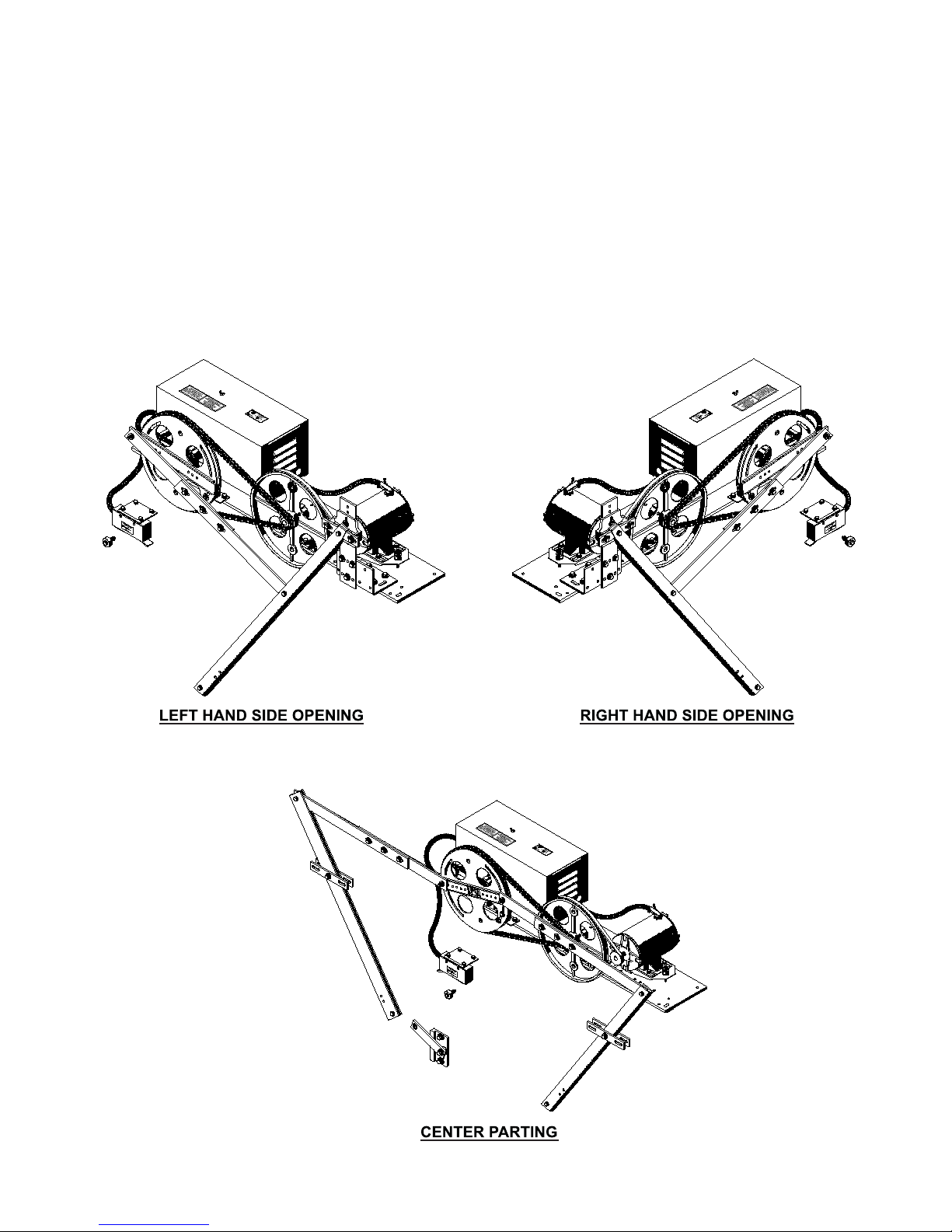
Side opening Doors:
With the header assembly correctly installed, the vertical centerline of the operator drive pulley should be
9 3/4” form daylite for a door opening of 22” to 44” and 14 3/4” for a door opening of 45” to 48” (see
figure 3 and Appendix drawings No. DATA21 and DATA22).
Center parting Doors:
With the header assembly correctly installed, the center of the door opening lines up with the center of
the header track. the center of the operator drive pulley should also line up with center of the opening
(see figure 6 and Appendix drawings No. DATA23).
Determining the position of the front edge of the door operator base:
Mount the drive arms to the drive arm support brackets on the header assembly for center parting doors
and to the drive arm support bracket for slide doors. The mounting brackets are slotted for fine
adjustment later, if needed. At this time, position the arms in the center of the bracket and tighten it.
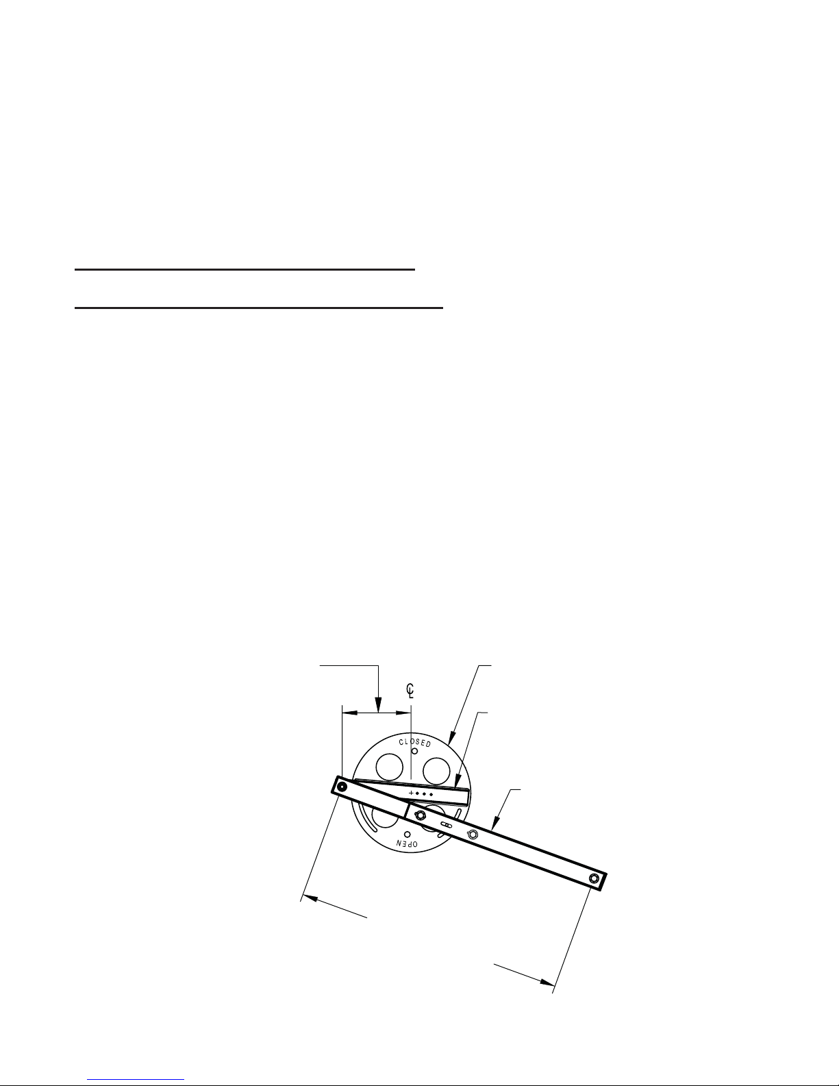
Attach the connecting linkage(s) to the drive pulley, making sure that when the word “CLOSED” is on top
the doors will be closed. Tighten the linkage(s) to drive pulley.
Attach the clutch assembly to the drive door linkage, then attach the clutch to the drive door using the
pre-tapped holes on the door panel. Tighten the clutch assembly to the drive door. Attach the other door
(for center parting doors) to its linkage and tighten the door bracket to the center of the slots.
Raise or lower the rear operator support bracket mounted to the cab to vertically level the operator drive
pulley. This helps to prevent binds in the opening and closing.
Check that the operator arms hang free and are not forced to or away from the operator drive pulley.
Slide the operator forward or backward, if necessary. Turn the drive pulley by hand making sure that the
G.A.L. Manufacturing Corporation December, 2007