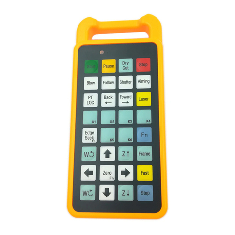
Friendess FSCUT4000 User manual

1
FSCUT4000 Laser Cutting Control System
FSCUT4000 Laser Cutting System
User Manual
Shanghai Friendess Co., Ltd
www.fscut.com
Ver. 2.0

FSCUT4000 Laser Cutting Control System
2
Thank you for choosing our products!
This manual gives a detailed introduction to the usage of
FSCUT4000 laser cutting controller, including technical features and
installation instructions etc. For CypCut laser cutting software
operation, please refer to the CypCut user manual. For other matters
you can contact us directly.
Operating personnel should read the manual in detail which will
be helpful for a better use of the product.
Due to the continuous updating of product functions, the products
you receive may differ from the statement in this manual in some
respects. We apologize for any inconvenience it may cause.

3
FSCUT4000 Laser Cutting Control System
Content
1. Product Description ........................................................................................................................6
1.1 Brief Introduction...................................................................................................................6
1.2 Connection Diagram ..............................................................................................................6
1.3 Technical Reference ...............................................................................................................7
1.4 Control Card Installation .......................................................................................................8
1.4.1 Install steps.............................................................................................................8
1.4.2 Troubleshoot...........................................................................................................9
2. BCL3724 Wiring Instruction .......................................................................................................11
2.1 BCL3724 Description ..........................................................................................................11
2.2 Signal Type ...........................................................................................................................12
2.2.1 Input signal...........................................................................................................12
2.2.2 Relay output.........................................................................................................14
2.2.3 Thyristor output ...................................................................................................14
2.2.4 Analog output.......................................................................................................15
2.2.5 PWM output.........................................................................................................15
2.3 I/O Specification...................................................................................................................15
2.3.1 External power supply.........................................................................................15
2.3.2 Servo control port ................................................................................................15
2.3.3 Servo drive control signal ...................................................................................17
2.3.4 Origin and limit....................................................................................................24
2.3.5 Common input .....................................................................................................24
2.3.6 Common output ...................................................................................................24
2.3.7 Analog output.......................................................................................................25
2.3.8 PWM output.........................................................................................................25
2.4 Wiring Diagram....................................................................................................................26
2.5 Laser Wiring Diagram..........................................................................................................27
2.5.1 YAG laser.............................................................................................................27
2.5.2 CO2 laser..............................................................................................................27
2.5.3 IPG-YLR..............................................................................................................28
2.5.4 IPG_ YLS Germany ............................................................................................29
2.5.5 IPG_ YLS American............................................................................................30
2.5.6 SPI-500W-R4.......................................................................................................31
2.5.7 FEIBO MARS......................................................................................................32
2.5.8 JK/GSI-FL............................................................................................................33
2.5.9 Rofin.....................................................................................................................34
2.5.10 Raycus ..................................................................................................................35
2.5.11 Max.......................................................................................................................36
3. Machine Config Tool....................................................................................................................37
3.1 Installation and Operation....................................................................................................37
3.2 Password...............................................................................................................................37
3.3 User Interface .......................................................................................................................38
3.4 Mechanism Config...............................................................................................................39

FSCUT4000 Laser Cutting Control System
4
3.5 Return Origin Config...........................................................................................................42
3.6 Laser Configuration .............................................................................................................43
3.6.1 CO2 laser configuration ......................................................................................43
3.6.2 IPG laser configuration .......................................................................................44
3.6.3 Feibo/Rofin/SPI/GSI/JK laser configuration .....................................................45
3.6.4 Configuration of other laser type........................................................................46
3.7 BCS100 Configuration.........................................................................................................46
3.7.1 Use BCS100 as height control unit.....................................................................46
3.7.2 Use external device as height control unit .........................................................47
3.8 Gas System ...........................................................................................................................48
3.9 Alarm Configuration............................................................................................................48
3.9.1 Warning message .................................................................................................49
3.9.2 Emergency stop button........................................................................................49
3.9.3 Safety mode..........................................................................................................49
3.9.4 Custom alarm.......................................................................................................49
3.9.5 Allowed dual-drive error.....................................................................................49
3.10 Common input......................................................................................................................50
3.11 Common output....................................................................................................................51
3.11.1 Output configuration............................................................................................51
3.11.2 Auto lubricate.......................................................................................................51
3.11.3 Custom output......................................................................................................52
3.11.4 Regional output....................................................................................................52
3.12 Find Edge Setting.................................................................................................................52
3.13 BCP5045 Panel.....................................................................................................................53
4. Electrical System Adjustment......................................................................................................54
4.1 Power Supply Checking.......................................................................................................54
4.2 Basic Machine Motion Config Checking ...........................................................................54
4.3 Hardware Signal Checking..................................................................................................56
4.4 Basic Motion Test.................................................................................................................57
4.5 CypCut Basic Function Test ................................................................................................57
4.6 Position-Loop PID Self Adjustment....................................................................................57
5. Adjustment Steps..........................................................................................................................59
6. Common Problems in Close-Loop control .................................................................................60
6.1 Motor Runaway Error ..........................................................................................................60
6.2 Encoder and Speed Check Failed........................................................................................60
6.3 Position Error Too Large......................................................................................................60
7. Optimize Machine Motion Performance.....................................................................................62
7.1 Calculate Inertia Ratio and Preview Machine Performance Features...............................62
7.2 Motion Control Parameter Adjustment...............................................................................63
7.2.1 Motion control parameter description ................................................................63
7.2.2 Adjust cutting acceleration..................................................................................63
7.2.3 Adjust travel acceleration....................................................................................64
7.2.4 Adjust low pass filter frequency.........................................................................64
7.2.5 Curve precision and corner precision.................................................................65

5
FSCUT4000 Laser Cutting Control System
8. FAQ................................................................................................................................................66
8.1 Cutting is Slow or Jamming ................................................................................................66
8.2 Corner Over Burned.............................................................................................................66
8.3 Laser No Emission...............................................................................................................66
9. Appendix.......................................................................................................................................68
9.1 Fly Cut Operation Guide......................................................................................................68
9.1.1 Function................................................................................................................68
9.1.2 Function description............................................................................................68
9.2 Pitch Error Compensation....................................................................................................69
9.2.1 Pitch error compensation description .................................................................69
9.2.2 Mechanical origin ................................................................................................69
9.2.3 Measure pulse equivalent....................................................................................69
9.2.4 Mechanic error measure ......................................................................................70
9.2.5 Import measurement data to CypCut..................................................................71
9.2.6 The operation steps of pitch error compensation...............................................72
9.2.7 FAQ.......................................................................................................................73

FSCUT4000 Laser Cutting Control System
6
1.Product Description
1.1 Brief Introduction
FSCUT4000 is a high performance laser cutting system of close-loop control
developed by Shanghai Friendess Company. It is widely used in metal and non-metal
laser cutting application, has gained wide popularity among users at home and abroad.
This manual served as installation and operation guide for FSCUT4000 system.
FSCUT4000 system hardware table:
Item
Model
Qty.
Motion control card
BMC1214
1 pcs
I/O terminal board
BCL3724
1 pcs
62-pin cable (2m)
C62-2
1 pcs
Servo cable (1.5m)
C15-1.5
4 pcs
Control software
CypCut
1 pcs
Wireless handheld remote
WKB
1 pcs
NC panel (optional)
BCP5045
1 pcs
1.2 Connection Diagram
BMC1214 card adopts PCI interface. Dimension: 155mm*106mm. The socket
(DB62M) on control card connects with BCL3724 I/O terminal by C62-2 cable. Wiring
diagram shown below:

7
FSCUT4000 Laser Cutting Control System
BMC1214
PCI Card
BCL3724 I/O Board
X axis drive
Y1 axis drive
Y2 axis drive
C62-2
C15-1.5
C15-1.5
C15-1.5
Computer Case
JP1
W axis drive
C15-1.5
1.3 Technical Reference
Motion Control
Motion control
Motor control
signal
Analog output of 4 servo axis ports, -10V—+10V.
Encoder feedback channel of 4 servo axis ports, 10MHz.
Dedicated signal inputs of origin, positive/negative limit
and servo alarm for each axis.
Dedicated signal outputs of servo enable and alarm reset
etc., for each axis.
Motion
control
performance
Control cycle 1ms.
S-type acceleration and deceleration with filter.
Velocity look-ahead strategy, intelligent speed control at
turning point.
Local curvature analysis and speed restriction at curves.
Auto smooth corner.
Laser control signal
1 PWM signal, DIP switch(24V/5V as options)
3 analog output ports of 0~10V
1 analog input port of 0~10V
I/O function
12 common input ports.
20 output: 6 relay outputs and 14 thyristor outputs.
Work environment
Temperature: 0-55 Celsius degree
Humidity: 5% ~ 90% no condensation
Power supply
24V,2A

FSCUT4000 Laser Cutting Control System
8
1.4 Control Card Installation
1.4.1 Install steps
Please wear anti-static gloves to prevent possible electrostatic
damage to the motion control card.
(1) Power off computer, insert the control card into PCI socket, and fix the control
card tightly;
(2) After start up computer, "Add Hardware Wizard" pops out and click "Cancel"
button, as shown below. If this dialog box does not appear, indicating the card
is in poor connection, please repeat the first step.
(3) Install CypCut software. The driver program will be installed by default option
automatically.
(4) Open windows device manager to confirm installation succeed. Below image
shows the installation is succeed.

9
FSCUT4000 Laser Cutting Control System
1.4.2 Troubleshoot
(1)If "Find New Hardware" dialog box does not pop out after start up computer
or control card does not shown in device manager, indicating that the control
card is not in good connection with PCI socket. Please replace the PCI socket
or change another computer, insert the control card tightly and reinstall
software.
(2)If the device has a yellow exclamation mark, double-click to
open its attributes page, and select "Detail Information" as shown below:
(3)If the first half of the ‘device instance ID’ attribute is displayed as
it means computer has correctly recognized the motion
control card but software installation might be failed. Try install CypCut
again, if installation still fails, please contact our technical support.
(4)If the first half of ‘device instance ID’ attribute is not , it

FSCUT4000 Laser Cutting Control System
10
indicates computer doesn't recognize the control card. Power off computer and
change PCI socket, install the card firmly and repeat installation again.
(5)If step (4) still fails, the control card might be damaged please contact our
technicians.

11
FSCUT4000 Laser Cutting Control System
2.BCL3724 Wiring Instruction
2.1 BCL3724 Description
BCL3724 diagram shown as below:
X axis Y1 axis Y2 axis
IN12 11 10 IN9 8 7 IN6 5 4
62-pin socket
24V COM 24V 24V 24V
IN3 2 1
COM COM COM COM COM COM COM COM COM COM COM COM
D1+ D2+ D3+ AD+
COM COM COM
COM COM COM
X- XO X+Y1- Y1O Y1+
POWER IN
O7 O8 O9 O10O11O12
POWER OUT
Control
relay
Control
relay
Control
relay
BCL3724
1 2
ON
OFF
O13O14O15
O19O20COM
O16O17O18
COM COM COM COM COM COM
Y2- Y2O Y2+ W- W0 W+
W axis
Control
relay
D1- D2- D3- AD-
P- P+
NO1CON1NO2CON2NO3CON3NO4CON4NC6NO6CON6
NC5NO5CON5
Relay
output
Relay
output
Relay
output
Relay
output
Relay
output
Relay
output

FSCUT4000 Laser Cutting Control System
12
You can either use guide rail or fixed installation to installBCL3724 board, product
dimension 315mm*107mm. DB62M socket connected with JP1 interface of BMC1214
card by C62-2 cable.
4 sockets (DB15M) on top left are for servo control, from left to right is X, Y1, Y2
and W axis port.
The signal terminals on bottom left are positive/negative limit, origin inputs of X,
Y and W axes. All lower terminals are conducted, ground end of COM, 0V.
On bottom right are 20 common output terminals which are thyristor emitter output.
Thyristor output is 24V, common cathode.
Above are PWM signal and 4 DAanalog signal terminals.
There is a DIP switch down below PWM:
Switch P1 and P2 to set PWM voltage
P1
P2
Description
On
Off
PWM voltage is 24V
Off
On
PWM voltage is 5V
2.2 Signal Type
2.2.1 Input signal
The input signals: positive/negative limit, origin, common input. All input
terminals of BMC1214 are low-level active, support NO (normally-open) and NC
(normally-close) input. When set input as normally-open, input signal active when
conduct with 0V; when set input as normally-close, input signal active when disconnect
with 0V.
The polarity of input can be changed by jump-wire, IN10, IN11, IN12 support
jump-wire. There are 2 status of jump-wire, ACT_LOW means low-level active (input
0V active); ACT_HIGH means high-level active (input24V active). The default state is
ACT_LOW.

13
FSCUT4000 Laser Cutting Control System
ACT_LOW
ACT_HIGH
The typical wiring of photo-electric switch shown below, must use NPN 24V type
switch.
Photo-electric switch
COM
Y-
24V
—
O
C
+
BCL3724
The typical wiring of contact switch shown below.
Contact switch
COM
NO
COM
Y+
BCL3724
The typical wiring of magnetic switch shown below, must use NPN 24V type
switch.
COM
IN6
24V
BCL3724 Magnetic switch
0V
o
V+

FSCUT4000 Laser Cutting Control System
14
2.2.2 Relay output
There are 6 relay output on BCL3724 terminal board which are OUT1-OUT6.
OUT1-OUT4 only support normally open, OUT5-OUT6 have both NO and NC
options. The maximum load of relay: DC 30V, 8A; AC 250V, 8A. Recommend to
use load under 2A, the inductive load or high power load will reduce the service
time of relay switch.
Wiring between relay output and contact shown below:
BCL3724
24V
Digit
Machine
Coil power
supply
OUT1
2.2.3 Thyristor output
There are 14 thyristor output on BCL3724 from OUT7-OUT20, which can drive
24V DC device directly, drive capacity is 500mA. Wiring diagram shown below:
BCL3724
OUT16
COM
24V DC
Magnetic
valve

15
FSCUT4000 Laser Cutting Control System
2.2.4 Analog output
3 analog output of 0-10V.
2.2.5 PWM output
There is one PWM port on BCL3724 for laser average power modulation. There
are 5V and 24V for options. The duty cycle is adjustable from 0%~100%, the highest
carrier frequency 50 KHz. The signal output shown below:
PWM+
PWM-
PWM
VCC
Set PWM signal level, 5V or 24V set by DIP switch.
2.3 I/O Specification
2.3.1 External power supply
BCL3724 requires external 24V DC power supply. The 24V and COM connect
with 24V and 0V of power supply.
2.3.2 Servo control port
The 4 servo ports on BCL3724 are DB15 sockets, signal pin description listed
Output range
0V~+10V
Maximum output load
50mA
Maximum capacitive load
350pF
Input impedance
100KΩ
Maximum bipolar error
+/-50mV
Resolution
10mV
Conversion speed
400us

FSCUT4000 Laser Cutting Control System
16
below:
1 2 3 4 5 6 7 8
9 10 11 12 13 14 15
The signal pin description of C15-1.5 cable listed below:
15-pin servo control interface
Pin
Description
Pin
Description
1
DA (-10~10V analog)
9
AGND (analog ground)
2
0S (zero speed clamp)
10
0V (power supply ground)
3
A+ (encoder A phase positive)
11
A- (encoder A phase negative)
4
B+ (encoder B phase positive)
12
B- (encoder B phase negative)
5
Z+ (encoder Z phase positive)
13
Z- (encoder Z phase negative)
6
SON (servo enable)
14
ALM (alarm signal)
7
CLR (alarm clear)
15
0V (power supply ground)
8
24V (power supply)
+24V, 0V: give 24V DC power supply to servo driver;
SON: servo-on output;
ALM: alarm input from servo;
DA, AGND: analog output for motor control;
CLR: alarm reset;
OS: zero speed clamp signal;
A+ 、A- 、B+ 、B- 、Z+ 、Z-: Encoder 3-phase input signal, to check
encoder zero point.
The polarity of SON and ALM can be changed by jump-wire;
SON
ACT_LOW
ACT_HIGH
ALM
ACT_LOW
ACT_HIGH
SON signal jump wire to ACT_LOW, output islow-level active (output 0Vactive);
Jump wire to ACT_HIGH, output is high-level active (output 24V active); Default is
ACT_LOW.

17
FSCUT4000 Laser Cutting Control System
ALM signal jump wire to ACT_LOW, input is low-level active (input 0V active);
Jump wire to ACT_HIGH, input is high-level active (input 24V active); Default is
ACT_LOW.
2.3.3 Servo drive control signal
The wiring diagram with Panasonic,Yaskawa, Sanyo and Schneider provided here.
For servo driver parameter setting you can take reference from ServoTools calculation.
If you have any question please contact our technical support.
For other brand servo wiring please take notice of following items:
(1) Make sure the servo supports velocity control mode. For example, Panasonic
A5 series servo must choose full-function type, cannot use pulse type;
(2) Check if SON signal is low-level active (SON is active when conducted with
GND of 24V);
(3) Check if there is external emergency stop in servo I/O;
(4) Before trial run of driver, provide 24V power supply to IO terminal board, the
24V power supply provided by BCL I/O board;
(5) If driver still can't run, check if the parameter 'positive/negative direction drive
inhibit' in driver is disabled.

FSCUT4000 Laser Cutting Control System
18
Panasonic servo wiring diagram
FSCUT DB15 servo control MINAS-A 50P
Signal Pin SignalPin
DA 1
AGND 9
A+ 3
A- 11
B+ 4
B- 12
Z+ 5
Z- 13
24V 8
0V 10
ALM 14
14 SPR/TRQR
21 OA+
22 OA-
48 OB+
23 OZ+
49 OB-
24 OZ-
7 COM+
36 ALM-
37 ALM+
41 COM-
Shielding layer
SON 6
15 GND
29 SRV-ON
0V 15
Panasonic A5 reference setting
Parameter
Description
Recommended value
Pr0.01
Control mode
1
Pr0.02
Real time auto tuning
0
Pr0.04
Inertia ratio
You can calculate the inertia ratio by
Panasonic servo software
Pr0.11
Encoder output pulse
per motor revolution
Set by mechanism feature, the pulse equivalent
should be among 1000-2000. For example, if
the linear distance is 10mm on machine load
per motor rotation, the pulse per revolution
should be 10000, and Pr0.11 set 2500.
Pr1.01
1st gain of velocity
loop
75.0Hz
Pr1.02
1st time constant of
velocity loop
integration
9.0ms
P r1.04
1st time constant of
torque filter
0.3ms
P r3.02
Input gain of speed
command
Set by maximum motor speed. If maximum
motor speed is 4000rpm, set 400 here.

19
FSCUT4000 Laser Cutting Control System
Yaskawa servo wiring diagram
FSCUT DB15 servo control YaskawaΣ50P
Signal Pin SignalPin
DA 1
AGND 9
A+ 3
A- 11
B+ 4
B- 12
Z+ 5
Z- 13
24V 8
0V 10
ALM 14
5 V-REF
33 PAO
34 /PAO
35 PBO
19 PCO
36 /PBO
20 /PCO
47 +24 VIN
32 ALM-
31 ALM+
1 SG
Shielding layer
SON 6
6 SG
40 /S-ON
0V 15
Yaskawa Sigma 5/7 reference setting
Parameter
Description
Recommended value
Pn000
Control mode
0000
Pn100
Velocity loop gain
75.0Hz
Pn101
Velocity loop integral
constant
9 .00 MS
Pn103
Inertia ratio
Set by calculation result of Yaskawa
servo software SigmaWin. Or you
can set by calculation result of
ServoTools.
Pn170
Adjustment-free
1400
Pn212
Differential pulse output
per motor revolution
Set by mechanism feature, the pulse
equivalent should be among 1000-2000.
For example, if the linear distance is
10mm per motor rotation, the pulse per
revolution should be 10000, and Pr0.11
set 2500.
Pn300
Input gain of speed
command
0.01V/rated speed

FSCUT4000 Laser Cutting Control System
20
Pn401
Torque command filter
time constant
0.30 MS
Pn50A
Input signal
8100
Pn50B
Input signal
6548
Table of contents
Other Friendess Controllers manuals
Popular Controllers manuals by other brands

Smart power
Smart power AVR10-120TBF user guide

Tolomatic
Tolomatic 3604-9651 Hardware installation guide

Audio Control
Audio Control MVC Owner's enjoyment manual

IMG STAGE LINE
IMG STAGE LINE 25.5780 instruction manual

FOS Technologies
FOS Technologies DMX-6 user manual

Data Video
Data Video MCU-100 quick start guide