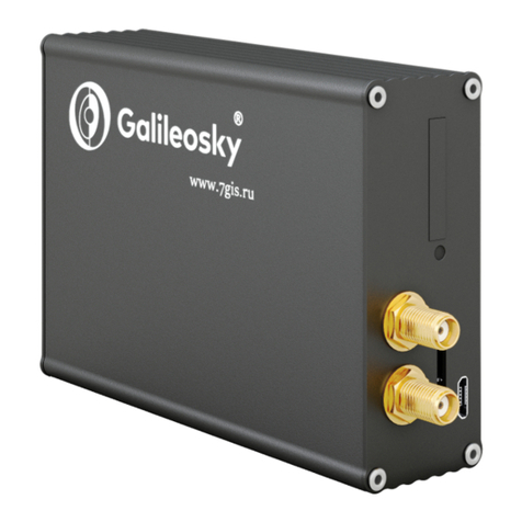
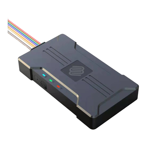
GalileoSky BOXFINDER User manual

BOXFINDER (0001) User’s Manual
RSA “Galileosky”, LLC. Page 1
BOXFINDER trackers
User’s Manual
firmware 0001
Quality
Reliability
Simplicity

BOXFINDER (0001) User’s Manual
RSA “Galileosky”, LLC. Page 2
Contents
Introduction........................................................................................................................................................4
1. Package.......................................................................................................................................................6
2. Technical specifications ..............................................................................................................................6
3. Safe operating rules....................................................................................................................................7
4. Contacts description...................................................................................................................................7
5. Algorithm of Tracker’s operating................................................................................................................9
6. Acoustic search...........................................................................................................................................9
7. Connecting................................................................................................................................................10
7.1. Inserting SIM-card.............................................................................................................................10
7.2. LED indication work ..........................................................................................................................10
8. Description of Tracker units’ operating....................................................................................................10
8.1. Description of universal input operation in analog mode ................................................................10
8.1.1. Mean value and discrete event generation ..............................................................................11
8.1.2. Frequency count........................................................................................................................11
8.2. Determination of strike.....................................................................................................................11
8.3. Transmitting monitoring data...........................................................................................................12
8.4. Remote configuration.......................................................................................................................12
9. Connecting external peripheral................................................................................................................13
9.1. Connecting 1Wire sensors ................................................................................................................13
9.1.1. Connecting iButton (DS1990, DS1982)identification key..........................................................13
10. Configurator..............................................................................................................................................14
10.1. Program installation and running .....................................................................................................14
10.2. Device tab .........................................................................................................................................15
10.3. Troubleshooting tab..........................................................................................................................17
10.4. Command mode tab .........................................................................................................................20
10.5. Graphic interface settings.................................................................................................................22
10.5.1. Security......................................................................................................................................22
10.5.2. Data transmission......................................................................................................................22
10.5.3. Protocol .....................................................................................................................................23
10.5.4. Power saving .............................................................................................................................23
10.5.5. Inputs/outputs ..........................................................................................................................24
10.5.6. Digital inputs .............................................................................................................................24
10.5.7. Sound ........................................................................................................................................25
10.6. Data loading and sending to server ..................................................................................................26
10.6.1. Data loading from the Tracker to file........................................................................................26
10.6.2. Sending data to server ..............................................................................................................26
11. Commands list ..........................................................................................................................................27
11.1. Setting for SMS control.....................................................................................................................27
11.2. Data transmission settings................................................................................................................27
11.3. Server exchange protocol settings....................................................................................................29

BOXFINDER (0001) User’s Manual
RSA “Galileosky”, LLC. Page 3
11.4. Information commands ....................................................................................................................31
11.5. Service commands ............................................................................................................................33
11.6. Voice communication settings..........................................................................................................34
11.7. Universal input setting......................................................................................................................35
11.8. Relay setting......................................................................................................................................35
12. GALILEOSKY protocol parameters ............................................................................................................36
13. Bootloader ................................................................................................................................................37
13.1. USB channel download .....................................................................................................................37
13.2. GPRS channel download ...................................................................................................................37
13.3. Using universal input to enter bootloader mode .............................................................................37
13.4. LED operation during reflashing .......................................................................................................37
14. Additional information .............................................................................................................................38

BOXFINDER (0001) User’s Manual
RSA “Galileosky”, LLC. Page 4
Introduction
RSA “GALILEOSKY”, LLC. produces GALILEOSKY trackers for GPS and GLONASS real time vehicles monitoring.
The Trackers determine the mobile object location recording the time and route as points with
geographical coordinates and send the data to the server to be further processed and sent to the traffic
controller panel.
In addition, a number of other vehicle parameters are recorded: the state of analog and discrete inputs of
the Tracker and the state of digital interfaces.
The Trackers can be used in any vehicle.
Information is sent to the server
through GPRS and then through the
Internet to the operator panel.
To prevent the data from disappearing,
when there is no GSM signal, each
GALILEOSKY Tracker
has an internal
nonvolatile FLASH memory.
Server
GPRS
GPRS
GPRS
GALILEOSKY Tracker
receives a signal about its
location from GPS,
GLONASS satellites and
processes inputs and
outputs data
Client software

BOXFINDER (0001) User’s Manual
RSA “Galileosky”, LLC. Page 5
The tracker provides the following opportunities:
Vehicles and cargoes monitoring;
Voice communication with the traffic dispatcher;
GSM enabled remote software update;
Continuous troubleshooting of the Tracker through the USB port;
Car alarm and remote engine start;
Securing stationary objects;
Setting the Tracker through SMS, GPRS, USB;
and others (see sections Tracker units’ operating and Connecting external peripheral).
The information sent by the tracker includes:
The exact Greenwich time and date;
Vehicle coordinates: latitude, longitude, height;
Vehicles speed and direction;
Inputs (buttons) and analog sensors state;
External digital sensors state;
and others (see details of transmitted data in section Server exchange protocol)
In addition, the company provides warranty service and technical support on its site http://7gis.ru and
forum http://forum.7gis.ru.
Before starting the work study the instruction carefully.

BOXFINDER (0001) User’s Manual
RSA “Galileosky”, LLC. Page 6
1. Package
The standard package includes BOXFINDER tracker (hereinafter referred to as the Tracker) and a cable
assembly. Everything extra should be bought separately.
You will also need:
1. Cable Mini USB B – USB A
1
2. Technical specifications
Parameter
BOXFINDER GSM
GLONASS/GSM receiver
Sensitivity: -165dBm
Cold start 35s
Hot start 1s
Coordinates determination
accuracy, 95% of time, not
worse
5 m
GSM modem
GSM 900/1800, GPRS class 10
GLONASS aerial
In-built
GSM aerial
In-built
SIM-card Format
micro-SIM
In-built microphone
yes
In-built bistable relay
maximum switching power: 60 W;
maximum switching DC voltage: 220 V;
maximum switching AC voltage: 250 V.
Universal input
Analog-discrete and pulse frequency mode:
- voltage interval – 0-33 V;
- maximum measured frequency – 4 khz;
- input resistance 5,5 kOhm to the ground.
Digital mode:
- 1-Wire.
1-Wire
yes
USB 2.0
Tracker setting, troubleshooting and reflashing
ADC resolution in bits
12
Accelerometer
In-built
Tamper sensor
yes
Internal battery
14 ah
Archive capacity
160 points
Transmission protocol
GALILEOSKY; adjustable length-tagged
Enclosure protection
IP65
Operating temperature range
-40...+85 °C
Service life
About 10 years, sending one point 2 times a day
Dimensions
125,0 mm x 102,0 mm x 42,0 mm
Weight
within 350 г
Body material
plastic
Warranty
2 years since the purchase date
Average service life
10 years

BOXFINDER (0001) User’s Manual
RSA “Galileosky”, LLC. Page 7
3. Safe operating rules
Before using the Tracker study the instructions of GSM/GPRS devices safe operating.
Attention!To avoid failure:
Make sure the contacts are connected correctly!
Unused contacts must be well insulated!
4. Contacts description
№
Contact
Description
1
R1
First relay contact
2
GND
Ground 1-Wire
3
IN
Universal input
4
R2
Second relay contact

BOXFINDER (0001) User’s Manual
RSA “Galileosky”, LLC. Page 8
1 2 3 4
1. MicroSIM-card adapter.
2. Mini USB B adapter.
3. Opening sensor.
4. Connecting battery adapter.

BOXFINDER (0001) User’s Manual
RSA “Galileosky”, LLC. Page 9
5. Algorithm of Tracker’s operating
Tracker has 2 operating modes:
1. Operating mode. Sensors’ scanning, coordinates determination, sending data to server, phone
calls and sending SMS are carried out in this mode.
2. Sleepmode. Tracker switches off all internal modules and does not perform any actions in this
mode.
After sensors’ scanning, coordinates determination and sending data to server in operating mode,
Tracker automatically switches to sleepmode.
Tracker can leave sleepmode in the following cases:
1. Finishing sleep time assigned in the settings.
2. Activating opening body sensor.
3. Determination of strike by accelerometer.
4. Activating on analog input. Activating zone is applied by command incfg0 (See section Universal
input setting).
6. Acoustic search
Tracker has a microphone. While having a phone call you may hear some noise around the tracker.
You can use this function to find the tracker, by producing loud sounds (e.g. honk) and evaluating their gain
and damping.

BOXFINDER (0001) User’s Manual
RSA “Galileosky”, LLC. Page 10
7. Connecting
7.1. Inserting SIM-card
Use a SIM-card with activated GPRS and SMS services.
Insert the card carefully without applying excessive force.
To eject SIM-card, press it.
7.2. LED indication work
Blinking frequency,
times
Description
3
GSM-module is switched on
2
GLONASS-module is switched on
1
GLONASS and GSM-modules are switched off, Tracker is in operating mode.
8. Description of Tracker units’ operating
8.1. Description of universal input operation in analog mode
To attach external sensors, the tracker has a universal input, which, in accordance with settings, can be
analog-frequency input or interface 1-Wire. Input function is set in Tracker settings (see section
Inputs/outputs). In section Contacts description input is set as IN.
Input specifications in analog mode:
Feature
Value
Maximum measured voltage
33 V
ADC resolution
12 bit
Maximum transmitted signal frequency
4 kHz
In analog mode input has the following settings:
Parameter
Explanation
Filter type (input
function)
0 - arithmetical average (also discrete input state is generated);
2 – frequency input.
Filter length to
calculate the mean
value
The greater this parameter, the more slowly the device responds to the input signal
change. With filter length equal to 1 - averaging does not happen.
It is necessary to set this parameter in 1 for frequency inputs.
Ranges for
response/
nonresponse areas
(logical 1 and 0)
To process discrete signals, it is needed to set ranges, where signal is equal to one
and zero. Discrete input statuses should be seen in the Status of Inputs field, but not
in the Input voltage.
While counting pulses or frequency, it is necessary to put the value equal to half the
pulse value into all the fields of the given group. (example: the pulses' amplitude is
5000 mV, so all the fields must take the value 2500 mV).

BOXFINDER (0001) User’s Manual
RSA “Galileosky”, LLC. Page 11
8.1.1. Mean value and discrete event generation
Let us consider the example with the
following input settings (see left-hand figure):
Filter type is 0;
Filter length is 5;
Logical one zone range is 8-33V;
Logical zero zone range is 0-3V.
The mean value is calculated continuously
and is put into the corresponding field IN.
At the same time, it is continuously checked
whether the calculated value belongs to the
logical zero and logical one range.
If it is in the range 8-33V, the corresponding
bit will find itself in the Status of Inputs field
and a point will be recorded.
At value coming into the indifference zone
(3V-8V), the former bit value will be saved to
the Status of Inputs field.
If the value is in the logical zero zone (0V-3V),
the corresponding bit in the Status of Inputs
field is set to zero.
Thus, we can see that the given bit changes
its state only in response or nonresponse
signal zones.
Example 2 (right-hand figure).
In contrast to example 1, response and
nonresponse zones have changed places.
8.1.2. Frequency count
To measure frequency in some sensors it is needed to pull frequency output from the sensor to plus sensor
supply with 1kOhm resistor. Otherwise, frequency count will be impossible.
8.2. Determination of strike
All devices can determine the Tracker’s strike, and at that moment the Tracker leaves sleepmode. Strike is
exceedance of set acceleration limit on any accelerometer axis.
Response zone,
logical 1
33
0
3
Nonresponse
zone, logical 0
Indifference zone
8
V
Nonresponse
zone, logical 0
33
0
3
Response zone,
logical 1
Indifference zone
8
V

BOXFINDER (0001) User’s Manual
RSA “Galileosky”, LLC. Page 12
8.3. Transmitting monitoring data
Tracker allows specifying the list of preferred GSM-networks. The main priority is given to networks from
the beginning of the list. Every network is specified with country’s code and operator’s code. Tracker
supports up to 30 networks (OPS0 command, section “Data transmission settings”). If it is impossible to
connect to one of the preferred GSM-networks, the Tracker connects to any network but does not establish
connection to the server, thus voice communication and SMS will be available according to a tariff of the
installed SIM-card.
The Tracker allows data transmission to the main and backup monitoring server. The Tracker accounts
transmitted data separately for each server, thus both will receive full archive with the track.
Transmitted data may be coded; XTEA3 algorithm (http://tomstdenis.tripod.com/xtea.pdf) is used for
coding. Commands and responses to them are not coded.
8.4. Remote configuration
Remote configuration can be performed through several data transfer channels:
1. SMS. The Tracker has a list of 4 authorized phone numbers, the messages from which are treated
as configuration commands. The available commands are described in the section “Settings for SMS
control”. A phone number can be added to the list of authorized numbers either in the
Configurator, or by sending a message with “AddPhone” command (section “Settings for SMS
control”).
2. GPRS. Commands can be sent from the monitoring data processing server. The format of the
commands is described in the section “Server exchange protocol settings”.
3. GPRS. Sending commands via Configurator and remote configuration server of RSA “GALILEOSKY”,
LLC. In this case, the Tracker supports two parallel connections: the first – with the monitoring data
processing server, and the second – with the remote configuration server. Remote configuration
can be enabled using RemoteConfig 1 command (section “Service commands”). It is possible to
send commands to the Tracker, to receive current information from connected sensors and to
receive troubleshooting messages, when working with the remote configuration server. Using the
Configurator, it is possible to create a command pack to configure the Tracker and to save it on the
server. These commands will be sent to the Tracker when it establishes the connection to the
server.

BOXFINDER (0001) User’s Manual
RSA “Galileosky”, LLC. Page 13
9. Connecting external peripheral
9.1. Connecting 1Wire sensors
It is possible to connect different 1-Wire interface sensors. They can work simultaneously. To work with 1-
Wire interface, universal input should be set-up for “1-Wire” mode.
9.1.1. Connecting iButton (DS1990, DS1982) identification key
There are several identification key applications:
•driver identification;
•trailer detachment identification.
In the same way, it is possible to connect devices emulating iButton, for example, RFID-codes readers.
The Tracker can support up to 8 identification keys with certain identifiers or two identification keys with
any identifier.
When using a microSD card, up to 1000 IK with certain identifier are supported.
By identification key applying to IN and GND contacts (”Contacts description”) the key number is entered
into the memory and four lower bytes are sent to the server without checksum. By key disconnection the
number turns to zero.
Eight key identifiers can be set using iButtons command (section “Digital inputs”) or in the Configurator on
“Settings\Digital inputs tab”. You should enter 4 lower bytes of iButton key number without checksum, in
hexadecimal system.
For example, full key hexadecimal number:
09 91 02 0С00 00 00 5С, where
09 – type of device (in this case, it is DS1982, for DS1990 – 01),
91 02 0С00 00 00– unique number,
5C – the checksum.
In this case, 91 02 0С00 must be entered.
By identification key applying with one of the certain identifiers, a correspondent bit will be set in iButton
connection status field. You may control it on the “Device” tab in the Configurator. Checking 1-Wire bus is
carried out only once while leaving the “sleepmode” by the Tracker.
DS18S20
iButton
IN
GND
iButton

BOXFINDER (0001) User’s Manual
RSA “Galileosky”, LLC. Page 14
10.Configurator
Configurator is a PC program, which allows:
•configuring the Tracker via graphic interface and with the help of commands;
•troubleshooting the Tracker with saving the results in a log-file;
•seeing the Tracker units state in real time mode;
•downloading monitoring data from the internal memory;
•sending the downloaded data to the server;.
32 and 64 bit OS are supported: Windows 7, Windows 8.
10.1. Program installation and running
Download the Configurator program from the site http://7gis.ru/en/podderzhka/programmyi.html and
launch it.
Attention! Program installation may require changes of crucial OS elements. Do not let your antivirus
program block the installer operation.
In case of a security system warning, confirm launching the program.
During the installation of the Configurator old drivers will be deleted and new ones will be installed. It is
possible to install the major version of the Configurator or a limited one. The latter one allows uploading
archive and receiving the current parameters of sensors, but not changing the settings.
Start the Configurator program (from Start menu\Programs\GALILEOSKY\Configurator). Turn on the
power of the Tracker and connect it to the computer via a USB cable.
After the Tracker connection, the program loads all the Tracker`s settings parameters automatically. If the
program identifies the Tracker, all the buttons on the vertical left-hand panel will be active.

BOXFINDER (0001) User’s Manual
RSA “Galileosky”, LLC. Page 15
10.2. Device tab
The tab displays information about the Tracker state and allows its resetting. Parameter values, which are
beyond the limits, wrong coordinates and responses on inputs are shown in red.
If there is a PIN code in the Tracker, the program will request it to access the settings. By wrong code
entering the Tracker will disconnect from the computer, reset, connect to the Configurator again and wait
for the right code enter.
For remote configuration and troubleshooting of the Tracker, click “Select device...” button. In the
appeared window, enter your login and password to get the access to the remote configuration server. You
can get the login and the password in RSA “GALILEOSKY”, LLC. department of technical support or by
clicking the “Register new user” button.

BOXFINDER (0001) User’s Manual
RSA “Galileosky”, LLC. Page 16
After successful authorization on the server, the form of trackers list management will become available.
When connecting for the first time, the list of the controlled trackers will be empty. To add the Tracker to
the list, click “Register Device” button. During registration the Configurator will request a password for a
particular Tracker, a factory password corresponds to IMEI of the Tracker; this can be later changed in the
Configurator by the user. Trackers may be grouped.
After selecting a particular Tracker, it can be controlled via Configurator, the same way as it occurs with the
USB connection.

BOXFINDER (0001) User’s Manual
RSA “Galileosky”, LLC. Page 17
10.3. Troubleshooting tab
This tab allows us to see the current device state through the device troubleshooting reports.
The troubleshooting mode has the following buttons:
1) Start /Stop
The time scale displays the information about the server connection, packet recording, updating
coordinates etc. and with a 10 sec interval.
2) Clear troubleshooting window
3) Save the Tracker`s troubleshooting results as a log-file which can be opened by any text editor.
4) Search in the troubleshooting history file.
GSM unit debug info
Troubleshooting
messages
Description
Possible causes
GSM. Success turn on.
GSM unit is powered.
Turning on is successful.
GSM. Not success turn
on!
GSM unit is powered.
Turning on is denied by the unit.
GSM. Success unit.
GSM unit initialization is successfully
performed.
GSM. Not success
unit!
GSM unit initialization failed.
GPRS. Activated.
GPRS service initialization is successfully
performed.
GPRS. Not activate.
GPRS service initialization failed.
GPRS is not activated on this SIM
card. Not enough money on the
account. GSM network is
overloaded.
GPRS. Success connect
to server.
Device server connection is successful.

BOXFINDER (0001) User’s Manual
RSA “Galileosky”, LLC. Page 18
GPRS. Not success
connect to server.
Device server connection is failed.
The Server access is denied or wrong
server settings for the device.
GPRS. Reconnect
Number=№
Number of server reconnections.
№ - reconnection number.
GPRS. Firstpack OK.
First packet has been sent to the server.
GPRS. Firstpack
False.[0]
The device has sent the first packet, but
there is no confirmation at TCP/IP level.
GSM network is overloaded. The
packet has been blocked by device
brandmauer or FireWall.
GPRS. Firstpack
False.[1]
The device has sent the first packet, but
there is no confirmation at the application
level.
GSM network is overloaded. The
server is not handling the first
packet.
SMS debug info
Troubleshooting message
Description
SMS. RX SMS.
A new SMS message is received
SMS. TelNum: +79112299922
received from a given phone number
Command: ID
ID command is received
SMS. TX OK.
Message is successfully sent
SMS delfromslot 1
handled SMS deleting (from the first SIM card slot)
Not reply SIM. Slot 1
no SIM card reply (from the first SIM card slot)
GSM. No SIM-card
no SIM card reply (the card is probably not inserted)
Internal Flash-memory (tracks memory) debug info
Troubleshooting messages
Description
MEM. Write point – 200
Point with sequence number 200 is recorded.
GPS-unit debug info
Troubleshooting information
Description
Possible causes
SAT. Coord refresh.
Coordinates for current record have been
updated by GPS unit. The vehicle is considered
to be moving, packet has not been filtered off.
SAT. Coord not refresh.
Coordinates for current record have not been
updated.
Filtering at stops is activated.
SAT. Temper is low than -40
Device temperature is lower than -40ºC.
Operation at lower temperatures is impossible.
SAT. Temper is high than 65
Device temperature is higher than +65ºC.
Operation at higher temperatures is impossible.
GLONASS. Message received.
Len = 401
Tracker received information from GLONASS
unit. 401 byte is received.
GPS. Message received. Len =
172
Tracker received information from GPS-module.
171 byte is received.
GPS. Change baud rate = 1
Attempt to set GPS unit rate. Attempt №1.
SAT. Fix = 1
Current position is fixed (0 – not fixed);
SAT. SatInUse = 7
7 satellites are used for navigation;
SAT. Valid = 1
Coordinates are right (they can be used for
location determination). This Valid is not
related to valid in packet and status.
Galileo uses GLONASS
Tracker uses GLONASS system.
SAT. Incorrect data from
GLNS/GPS module
Wrong data are received from the used unit
(probably because of processor overload)
SAT. Time out. Restart MCU
Tracker gets no data from receivers (GLNS/GPS)
SAT. High Speed = 200
Navigation speed data filter turned on (these
data will be skipped by the unit).
SAT. HDOP is high = 6
Navigation HDOP data filter turned on (these

BOXFINDER (0001) User’s Manual
RSA “Galileosky”, LLC. Page 19
data will be skipped by the unit).
SAT. Jump = 5000
Navigation coordinate data filter turned on
(leap to large distance occurred).
SAT. First start OK. Sat count
>= MIN
By the Tracker turning on, the unit must get
more MIN satellites (only in this case, the data
are reliable).

BOXFINDER (0001) User’s Manual
RSA “Galileosky”, LLC. Page 20
10.4. Command mode tab
This tab is intended to message a single command or a set of commands to the Tracker.
The command mode has the following buttons:
1) Run commands;
2) Run single command;
3) Open from file;
4) Save to file.
The commands will be identified whether you use capital or lower-case letters or both in turn.
Attention!
There are no spaces in command name!
Spaces between parameters are not allowed!
Commands and parameters are separated by space.
Commands are separated by Enter.
Single command example
An example of a command with a parameter:
Enter APN internet.beeline.ru,beeline,beeline as shown in the figure above and press Run single command
button. The command and a response will be displayed in the Responses window.
Command: APN internet.beeline.ru,beeline,beeline
Response: GPRS: APN=INTERNET.BEELINE.RU, user=BEELINE, pass=BEELINE
To access the parameters in the Tracker memory you should use a command without parameters!
An example of a command without a parameter:
“APN” command
Request: APN
Response: GPRS:APN=INTERNET.BEELINE.RU, user=BEELINE, pass=BEELINE;
Table of contents
Other GalileoSky GPS manuals

GalileoSky
GalileoSky Lite Series User manual

GalileoSky
GalileoSky Base Block Hard Wi-Fi User manual

GalileoSky
GalileoSky GLONASS/GPS Satellite v4.0 User manual

GalileoSky
GalileoSky gps light User manual

GalileoSky
GalileoSky v 7.0 User manual

GalileoSky
GalileoSky v 5.0 User manual

GalileoSky
GalileoSky Base Block User manual

GalileoSky
GalileoSky Base Block User manual

GalileoSky
GalileoSky GLONASS/GPS v2.3 User manual

GalileoSky
GalileoSky GLONASS/GPS Satellite v4.0 User manual