Galvin Specialised CliniMix Lead Safe TMV SS Instruction sheet

Version 1, 15 June 2020, 1 of 16
CliniMix®Lead SafeTM TMV SS Cabinet Assembly
with Universal Door 20 Bottom In & Out
PRODUCT CODE:
- 101.10.70.10
TABLE OF CONTENTS
1.0 INTRODUCTION..........................................................................................................................1
2.0 SAFETY .......................................................................................................................................2
3.0 DESCRIPTION.............................................................................................................................2
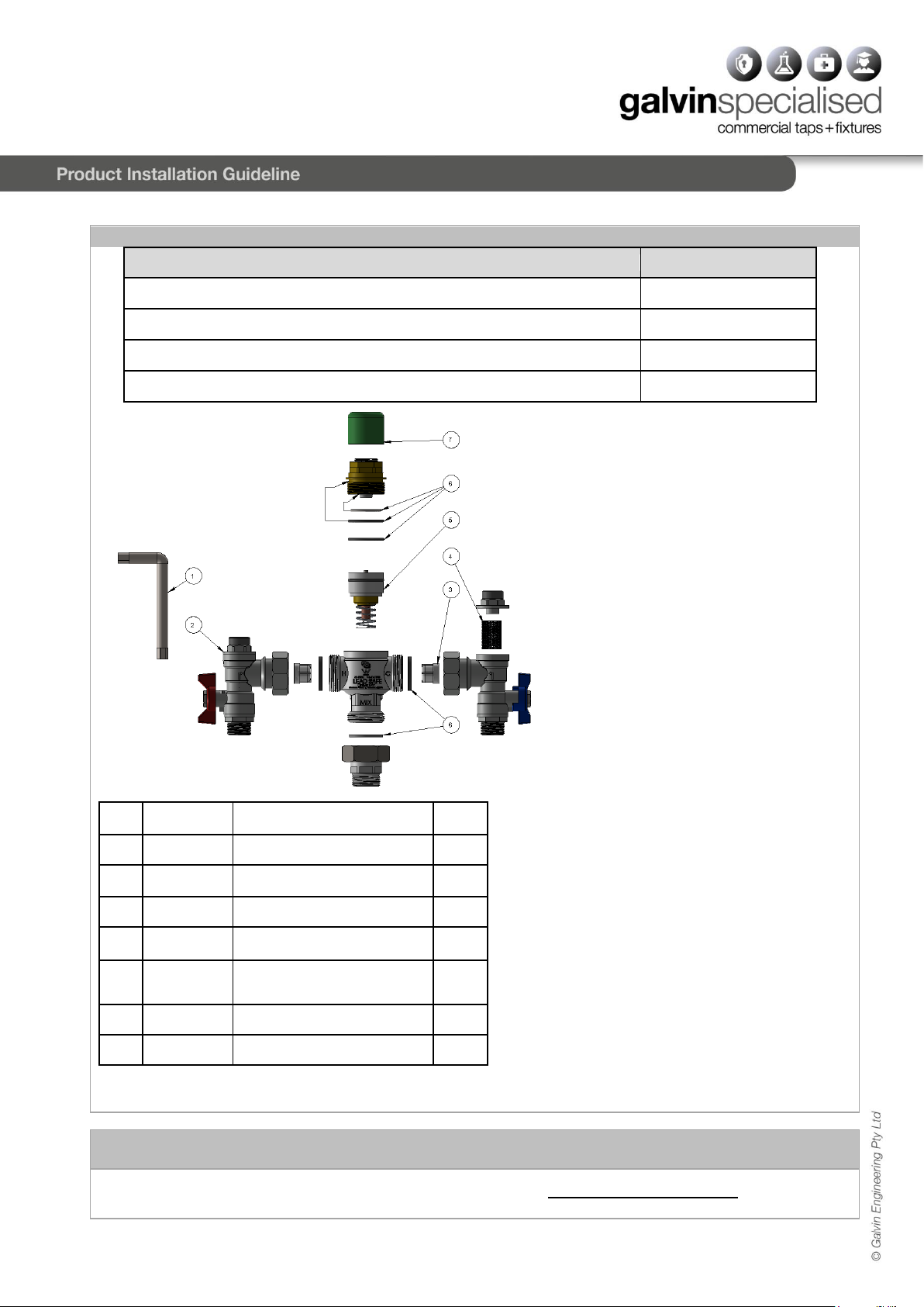
4.0 DIMENSIONS...............................................................................................................................2
4.1 TECHNICAL DATA......................................................................................................................3
4.2 FLOW SIZING GRAPH................................................................................................................3
5.0 WATER SUPPLY CONDITIONS.................................................................................................4
5.1 INTRODUCTION..........................................................................................................................4
5.2 SUPPLY PRESSURE REQUIREMENTS....................................................................................4
6.0 INSTALLATION...........................................................................................................................5
7.0 COMMISSIONING .......................................................................................................................6
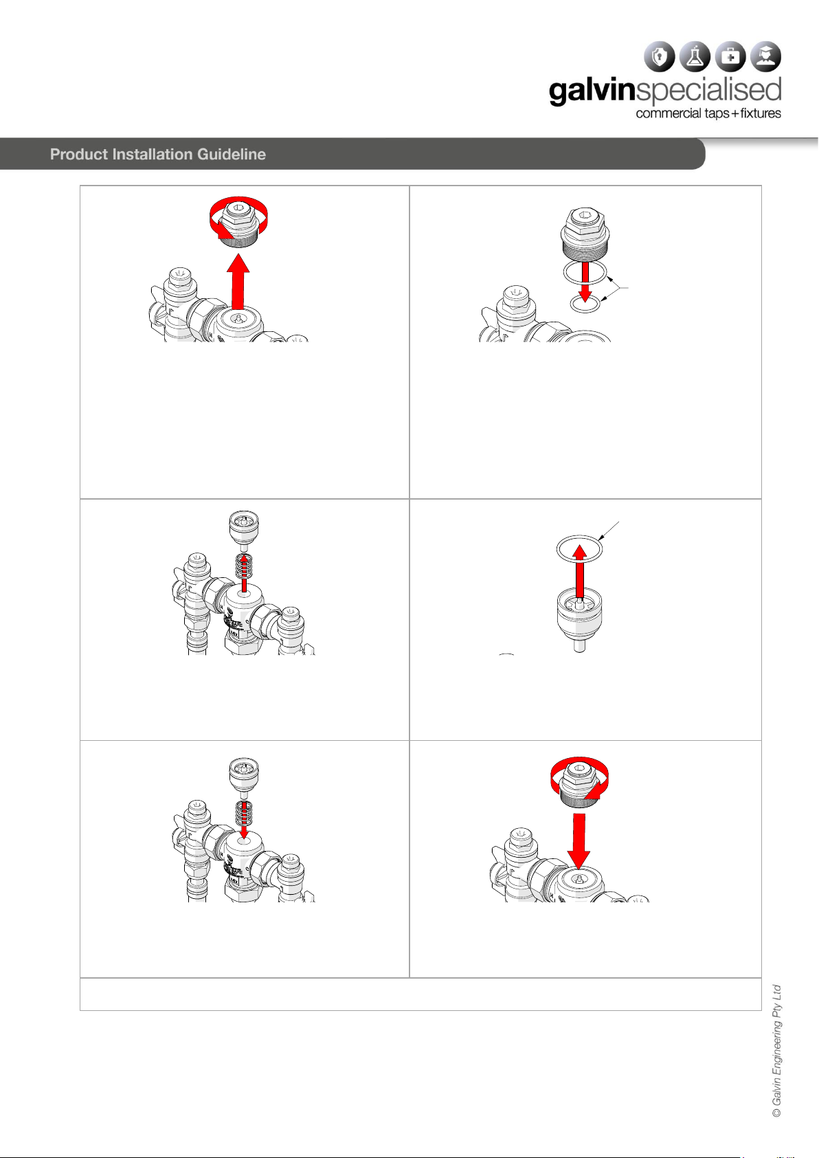
8.0 MAINTENANCE AND SERVICING.............................................................................................7
9.0 DISINFECTION..........................................................................................................................10
10.0 WARRANTY...........................................................................................................................11
11.0 TROUBLESHOOTING...........................................................................................................12
12.0 APPENDIX .............................................................................................................................13
1.0 INTRODUCTION
−CliniMix®Thermostatic Mixing Valve Cabinets are designed to protect users from scalding or cold water
shock by providing tempered water to the desired outlets.
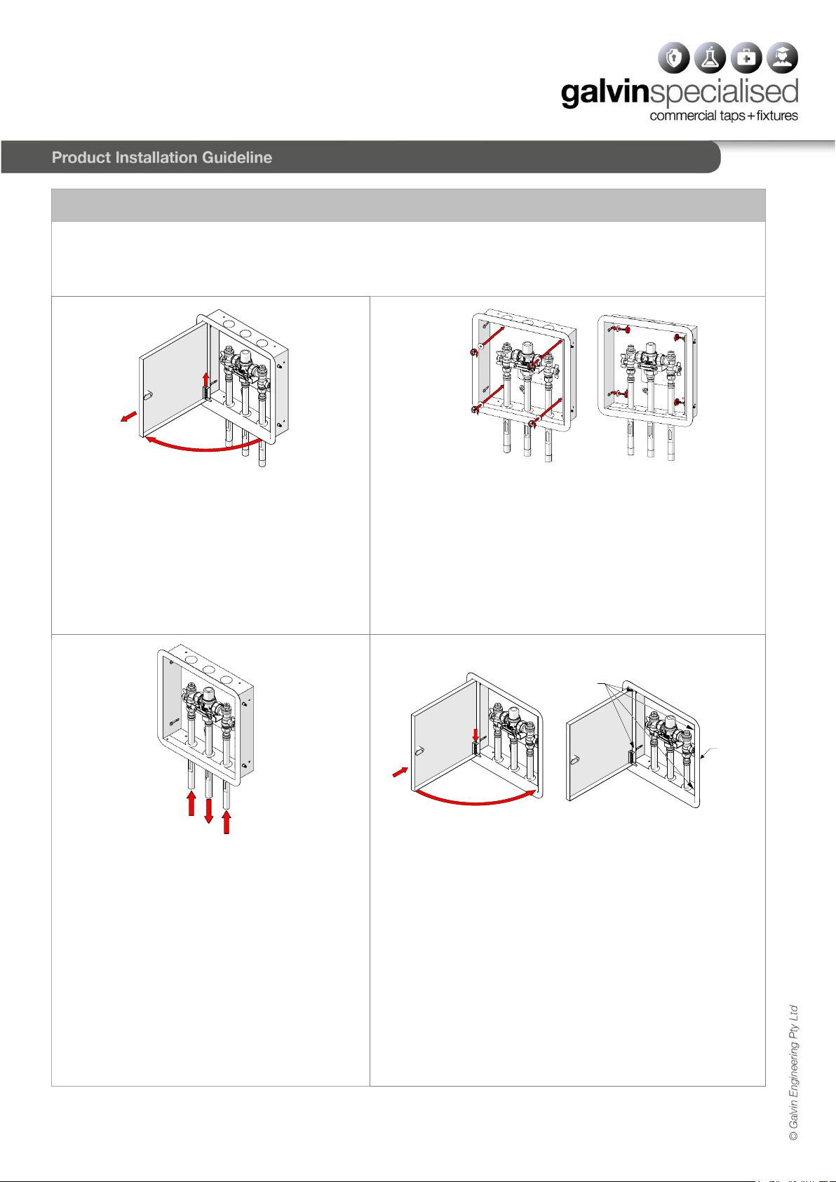
−This stainless steel hinged cabinet kit is a lockable cabinet with 20mm copper fittings (2 in and 1 out), which
allows secure installation and safe, simple maintenance of thermostatic mixing valve.
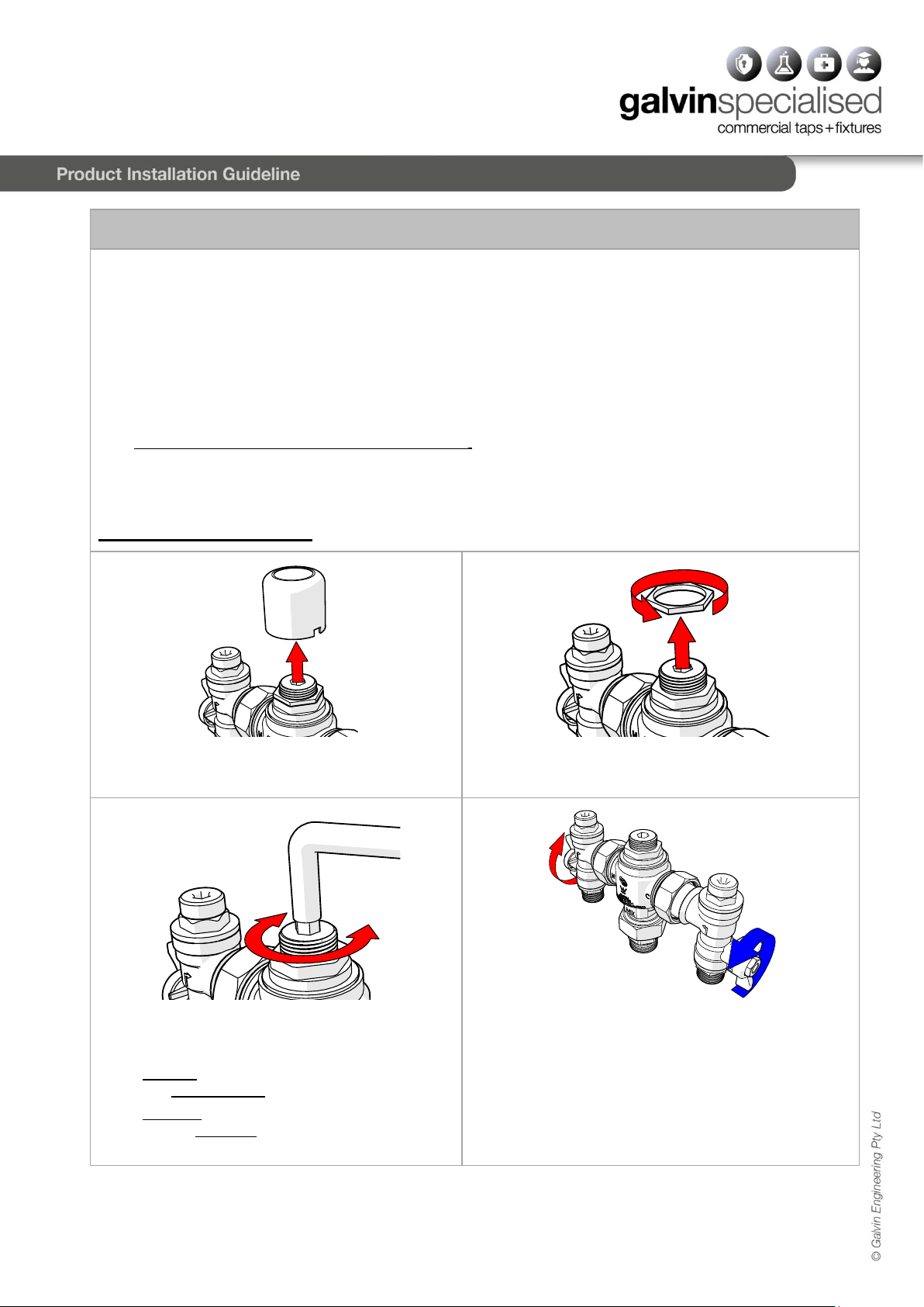
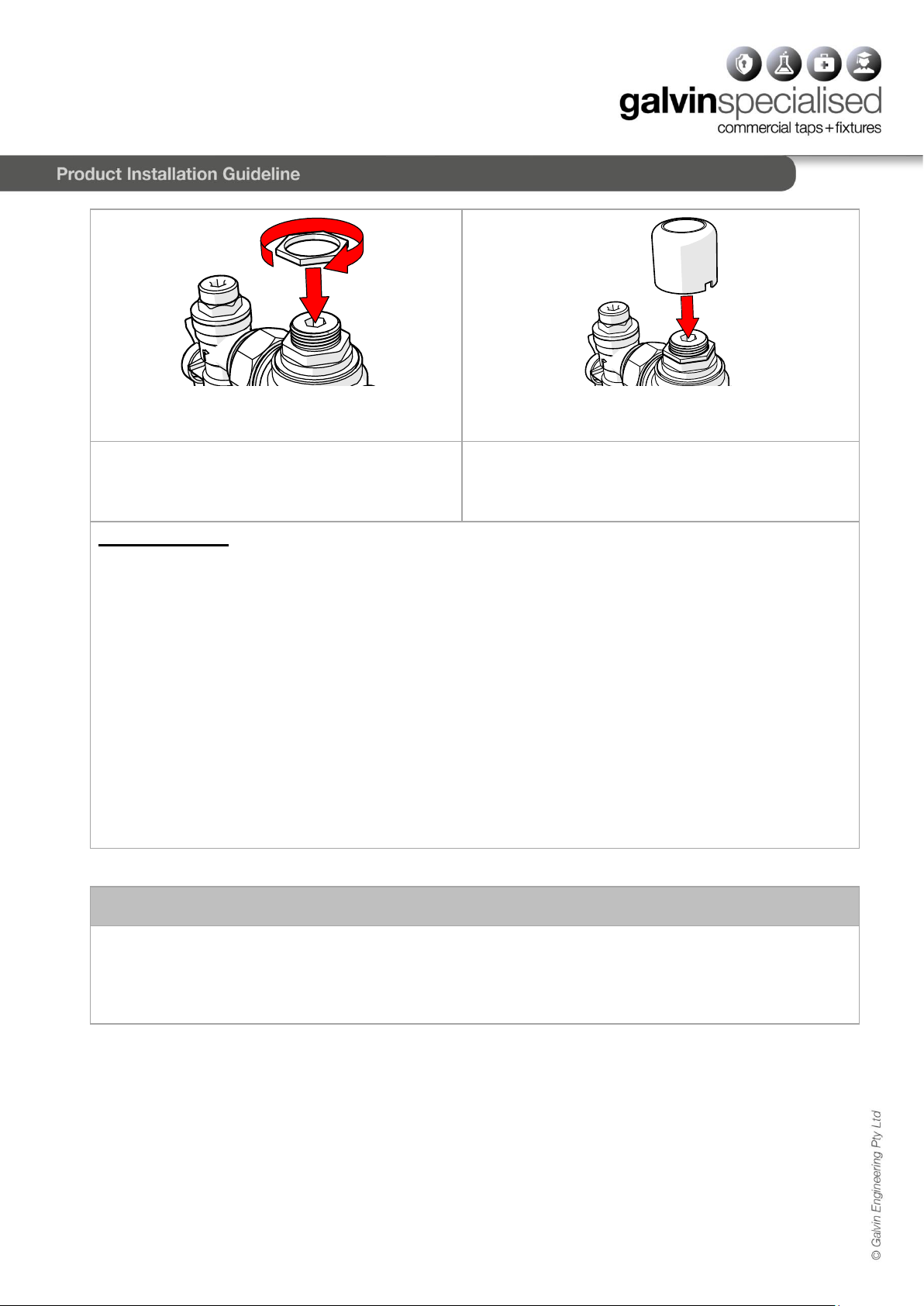
−Flat faced connections allow removal of the valve without disturbing the pipework.
−In the event of either hot or cold water supply failure the valve will shut down.
−Suitable for installation in low pressure systems and will operate with a working pressure as low as 20kPa.
−Units come complete with right angle isolating ball valve, non-return valve and strainer assemblies.
−Can be installed in any configuration with the water outlet in the horizontal or vertical position, and inlet
connections can be rotated to suit inlet pipework.
−Complies with the requirements of AS/NZS 4032.1 Thermostatic Mixing Valves.

Version 1, 15 June 2020, 2 of 16
2.0 SAFETY
The CliniMix®Lead SafeTM TMV SS Cabinet Assembly is a high-performance valve designed to give stable and
dependable operation, provided it is installed, commissioned, operated and maintained as per the
recommendations outlined in this manual. It should be noted, however, that this valve should not be considered
as an alternative to adequate supervision and duty of care during its use and operation.
Note: The mixing valve, inlet controls, pipe work and the surrounding area may become hot when
installed which may cause burn injuries. Precautions should be taken to ensure that these surfaces
cannot cause such injuries.
3.0 DESCRIPTION
This manual covers the CliniMix®Lead SafeTM TMV SS Cabinet Assembly with Universal Door 20 Bottom In
& Out. These are designed to provide tempered water to the desired outlets. This mixing valve cabinet
assembly is supplied with integral isolating valves, strainers and check valves and is provided with a facility
for thermal disinfecting of the cold inlet side and mixed water outlet.
Avoid using heat for soldering near the mixer inlets to prevent damage to internal components.
4.0 DIMENSIONS
−Cabinet to suit rough-in wall opening area
310mm width x 310mm height x minimum 75mm
maximum 105mm depth.
−Cabinet secured using back mount or side
mount.
−Measure and mark the cabinet mounting holes
locations at the dimenions shown in below
mounting details image.
−Suitable fasteners will need to be sourced by the
installer.
BACK MOUNT SIDE MOUNT

Version 1, 15 June 2020, 3 of 16
4.1 TECHNICAL DATA
MIXED OUTLET TEMPERATURE
Factory Preset Temperature (°C)
43.5
Adjustable Temperature Range (°C)
35 48
INLET TEMPERATURES
Cold Supply (°C)
Min
5
Max
25
Hot Supply (°C)
Min
60
Max
90
Temperature Differential (between supply and the outlet) for Stable Operation (°C)
Min
10
Nominal Flow Rate (LPM) (Per Graph)
Min
6
DYNAMIC INLET PRESSURES
Hot and Cold Inlet Pressures
Min
20
Max
500
STATIC INLET PRESSURE
Hot and Cold Inlet Pressures (kPa)
Max
1000
INLET PRESSURE RATIO
Maximum Inlet Pressure Ratio for Stable Operation
(Either supply) (Hot ; Cold or Cold : Hot)
6:1
NOTE 1: for optimum operation it is recommended that the hot and cold water supply pressure be balanced to within +/- 10%
NOTE 2: Notwithstanding the above, compliance with AS/NZS3500 must be maintained.
4.2 FLOW SIZING GRAPH
The Galvin Engineering CliniMix® Thermostatic Mixing Valve is suitable for many applications. The Head-loss
Characteristic for Mixed Outlet Flow rate versus Balanced Inlet Pressure is shown below in Graph below. It is important
that the valve is not oversized for its intended application. GRAPH Head-loss Characteristics
NOTE: To ensure optimum performance the minimum
outlet flow of the TMV during operation should be at
least 6 litres/minute.
It is important that the valve is sized such that the flow
rates from the outlets are not less than those listed
AS/NZS 3500.1
The pipe-work between the TMV and the system must be
sized in accordance with AS/NZS 3500.1 to ensure the
watervelocityinthepipe-workiswithintheallowedlimit.
If the TMV is to be installed and operated under unequal
inlet pressures, the lower inlet pressure determines the
outlet flow rate. However, for optimum performance and
stability it is recommended that the TMV be installed
with balanced dynamic inlet pressures (+/- 10%).

Version 1, 15 June 2020, 4 of 16
5.0 WATER SUPPLY CONDITIONS
5.1 INTRODUCTION
This mixing valve cabinet assembly is manufactured to the highest standards and has approval to AS4032.1
which permits it to be installed in healthcare establishments such as hospitals, nursing homes and residential
care homes. When installed in healthcare establishments the supply conditions detailed in Table 2 must be
observed and the commissioning and servicing requirements detailed on section 7 & 8 must be followed.
5.2 SUPPLY PRESSURE REQUIREMENTS
This mixer is designed to be installed on all types of plumbing systems.
Hot and cold water supply pressures should be reasonably balanced; however, the mixer will function within
specification on unequal pressures up to 6:1.
The mixer has integral isolating valves which permit servicing of the strainer, check valve/flow regulator and
thermostatic cartridge. They are also used for thermal disinfection.
The minimum pressure for the correct thermal operation is 20kPa. However, to achieve an acceptable flow
performance at very low pressures it may be necessary to remove the combined check valve and flow regulators
and replace them with simple check valves to facilitate thermal disinfection.
Working Temperature Range (°C)
Min
5
Max
90
Working Pressure Range (kPa)
Min
20
Max
500
Maximum Static Pressure (kPa)
1000
Permitted Supply Pressure Variation
6:1
Table 2. Water supply conditions
Note: Tapware must be installed in accordance with the provisions of AS/NZS 3500. Installations not
complying with AS/NZS 3500 may void the product and performance warranty provisions.

Version 1, 15 June 2020, 5 of 16
6.0 INSTALLATION
IMPORTANT: Galvin Specialised products must be installed in accordance with these installation instructions
and in accordance with AS/NZS 3500, the PCA and your local regulatory requirements. Water and/or electrical
supply conditions must also comply to the applicable national and/or state standards. Failing to comply with
these provisions shall void the product warranty and may affect the performance of the product.
BACK MOUNT SIDE MOUNT
1. Remove cabinet door
1. Open the cabinet door
2. Push hinge up to allow removal of the door.
3. Remove the door from cabinet.
2. Secure the cabinet
−Insert cabinet into wall opening.
−Mount cabinet in wall using four fasteners, only securing
hand tight.
−If side mounting, make sure door frame has clearance
and can slide after fastening the cabinet.
Note: The cabinet must be mounted with four fasteners for
stability and strength. This is critical, failure to do this may
void the warranty.
3. Connect water lines
−Before connecting to water lines, all lines must
be flushed
−Remove protective vinyl cap from copper tubes.
−Join each copper tube to the correct main water
line, taking note of flow direction arrows. Use
suitable copper joining methods, ensuring no
flash sits inside the pipeline, this will cause
damage to the valves.
Note: The Galvin Engineering CliniMix
Thermostatic Mixing Valve must be installed by a
licensed plumber. If the valve is not installed
correctly then it will not function correctly and
may put the user in danger. It may also void the
warranty of the valve.
4. Testing and operation
−Adjust the door door frame until sits flush with wall.
Completely tighten mounting fasteners and apply sealant
if necessary.
−Turn on hot and cold water supply.
−Check for any leaks
−Carry out commissioning procedure (see Section 7.0)
−Check temperature of water is correct. If not, see water
temperature adjustment settings (see Section 7.0).
−Fit hinged door back into cabinet and lock with supplied
key. Ensure instructions are placed in the cabinet for
future service and maintenance record.

6
Version 1, 15 June 2020, 6 of 16
7.0 COMMISSIONING
Upon completion of the installation, the TMV must be tested and commissioned as per the procedure outlined below.
The entire procedure should be read through thoroughly prior to the commissioning of the TMV. A calibrated digital
thermometer having rapid response time with maximum temperature hold, a small flat bladed screwdriver, adjustable
spanner and the adjusting key (suppliedwith the TMV) will berequired to checkand set outtheoutlet mixed temperature
of the TMV.
−Ensure all outlets that will be serviced by the TMV have adequate warning signs posted to ensure that no outlet
is used during commissioning.
−Open the cold supply line to the valve, and then open the hot water supply line, ensuring there are no leaks.
−Open the outlet that is serviced by the shortest length of pipe work between the mixing valve and outlet fixture.
−Allow the mixed outlet to flow for at least 60 seconds to allow the temperature to stabilise before taking a
temperature reading at the outlet with a digital thermometer. The flow rate should be at least 6 L/min. The flow
rate can be checked with the aid of a known size container and a stopwatch.
−If the outlet temperature requires adjustment the following steps are requires;
TEMPERATURE ADJUSTMENT
1. Using a small flat bladed screwdriver lever the
protected cover off the Thermostatic Mixing Valve.
2. Release the Temperature Locking Nut with an
adjustable spanner.
3. Fit the supplied key over the adjusting spindle
(figure 3).
To increase the mixed outlet temperature, rotate the
spindle anti-clockwise.
To decrease the mixed outlet temperature, rotate
the spindle clockwise.
4. Allow the mixed outlet temperature to stabilize for 60
seconds and once again take a temperature reading.
Repeat the procedure until the desired temperature has
been reached.

7
Version 1, 15 June 2020, 7 of 16
5. Retighten the Temperature Locking Nut with and
adjustable spanner
6. Push the top cover firmly on to the top of the valve until
7. Check the outlet temperature is stable over a full
range of flow rates and that the flow rate is
adequate for the application.
8. Close the outlet. The TMV is now set and locked.
SHUT DOWN TEST
Now that the TMV has been set and locked it is necessary to perform a shutdown check. Allow the mixed water
temperature to stabilize and note the outlet temperature. While holding a digital thermometer in the outlet flow,
quickly isolate the cold water supply to the valve. The outlet flow should quickly cease flowing. As a rule of thumb
the flow should be less than 0.1L/min following the isolation. Monitor the maximum outlet flow temperature, and
record this on the Commissioning Report (Appendix A). The temperature should not exceed that allowed by the
applicable standard or code of practice for each state and territory. Restore the cold water to the TMV. After the
mixed water temperature has stabilized note the outlet temperature ensuring the outlet temperature has
reestablished.
Now repeat the above test, except this time quickly isolate the hot water supply to the valve. The outlet should
quickly slow to a trickle. As a rule of thumb, the trickle should typically be less than 0.4L/min @ 500kPa down to
less than 0.1L/min @ 100kPa following the isolation. Restore the hot water supply to the valve and measure and
record the outlet temperature has stabilized ensuring the outlet temperature has reestablished.
Ensure that all details of the Commissioning Report are completed and signed by the relevant signatories. A copy
of this report should be kept with the installer and owner of the premises.
The valve is now commissioned and it can be used within the technical limits of operation.
8.0 MAINTENANCE AND SERVICING
The Galvin Engineering CliniMix®Thermostatic Mixing Valve will only require minimal preventative maintenance
work to ensure it operates at its optimum level of performance. The valve should be commissioned and serviced
annually, unless the installed conditions dictate more frequent servicing is necessary.

8
Version 1, 15 June 2020, 8 of 16
ANNUAL MAINTENANCE PROCEDURE
The Galvin Engineering CliniMix®TMV should be inspected and tested annually. The valve should be given a light
wipe down of the external surface. The TMV and surrounding areas should be inspected for leaks or water
damage and appropriate action taken if required.
Ensure the cabinet is clean before starting. Firstly, isolate the hot andcold supplies to theTMV by closing the inlet
ball isolators. Remove the inlet fitting top cover with a suitable spanner and then remove the mesh strainer. Clean
with a de-scaling solvent (such as CLR), check for physical damage and then thoroughly rinsed with clean water.
The strainers can then be re-installed into the valve, and the top cover replaced and tightened to a maximum
torque of 15Nm into the hot and cold inlet service fitting.
If the TMV fails to shut down or fails to maintain its set temperature, then refer to the fault finding solutions outlined
in Section 11.0.
The valve piston o-ring and thermostatic element / piston assembly must be replaced at intervals not exceeding
5 years.
Check that the test plugs in thetop of the inlet fittings are tight and that there is no evidence ofwater leakage.The
TMV must then be recommissioned as per Section 7.0, including temperature adjustment and the shutdown test.
INSTALLATION INSTRUCTIONS FOR THERMOSTATIC ELEMENT/PISTON ASSEMBLY
1. Ensure the cabinet is clean before starting.
2. Isolate the hot and cold supplies to the mixing valve by closing the inlet ball valves.
3. Pry off the plastic cap using a small screwdriver or similar.
4. Remove brass Top Assembly with a suitable spanner. Care must be taken to ensure that the underside of
the Top Assembly does not receive even the slightest damage.
5. Gently remove the element/piston assembly.
6. Lightly grease O-rings if required. (use only potable water approved silicon-based lubricating grease such
as Molykote111)
7. Insert new element/piston assembly taking extreme caution not to damage any surface of the piston.
8. Refit the TMV Top assembly back to the body and tighten to a maximum torque of 10Nm.
9. The valve must then be recommissioned as per section 7.0 including temperature adjustments and shut
down test.
INSTALLATION INSTRUCTIONS FOR O-RING REPLACEMENT
1. Ensure the cabinet is clean before starting.
Isolate the hot and cold supplies to the TMV by
closing the inlet isolator valves.
2. Remove the plastic cap.

9
Version 1, 15 June 2020, 9 of 16
3. Unscrew brass top assembly with a suitable
spanner (26mm). Care must be taken to ensure
that the underside of the cap does not receive
any damage.
4. Remove O-ring from thread of top assembly.
Replace the largest O-ring supplied in the kit
(adequately grease O-rings with potable water
approved silicon-based lubricating grease such as
Molykote 111 before refitting).
Remove wire circlip from brass top assembly,screw
out the plastic spindle and replace the smaller
O-ring.
5. Carefully remove the spindle from the center of
the body.
6. Remove O-ring from spindle. Replace with O-ring
supplied in the kit. (adequately grease O-rings with
a potable water approved silicon-based lubricating
grease such as Molykote111 before refitting).
7. Insert cartridge assembly taking extreme
caution not to damage any surface of the piston.
8. Refit the TMV top assembly back to the body and
tighten to a maximum torque of 10Nm.
9. The valve must be recommissioned as per section 7.0 including temperature adjustments and the
shutdown test.

10
Version 1, 15 June 2020, 10 of 16
8.1 SPARE PARTS
Part
Replacement Period
O Ring Kit
5 yearly
Thermostatic Element Assembly (incl. Thermostatic Element/Piston Assembly)
5 yearly
Face Seal Washer
As required
Inlet Fitting Strainer (two)
As required
ITEM
ITEM NO.
SALES SPARE DESCRIPTION
QTY
1
WM-KEY-1
TEMPERATURE ADJUSTMENT
KEY FOR WM-TMV1
1
2
WM-ISO-1
INLET ISOLATOR ELBOWS (PAIR)
FOR WM-TMV1
1
3
WM-NRV-1
INLET NON-RETURN VALVE FOR
WM-TMV1 (PAIR)
1
4
WM-STR-1
INLET STRAINERS FOR WM-TMV1
(PAIR)
1
5
WM-TPKIT-1
THERMOSTAT, PISTON/SHUTTLE
ASSEMBLY & SPRING FOR WM-
TMV1
1
6
WM-SKIT-1
SEAL & O-RING KIT FOR WM-
TMV1
1
7
WM-ATC-2
ANTI TAMPER CAP FOR WM-
TMV1 (GREEN)
1
NOTES: IF THE ITEM NUMBER IS NOT LISTED, THE COMPONENT IS NOT AVAILABLE INDIVIDUALLY
9.0 DISINFECTION
A thermal disinfection kit is available. For more information please visit www.galvinengineering.com.au.

11
Version 1, 15 June 2020, 11 of 16
10.0 WARRANTY
The Galvin Engineering CliniMix®Thermostatic Mixing Valve is guaranteed free from manufacturing faults for a
period of 12 months, subject to the conditions and exclusions set out below;
GALVIN ENGINEERING PRODUCT WARRANTY
Galvin Engineering products are warranted to be free from defects in materials and/or workmanship for a period
of 12 months service life, and if found by Galvin Engineering to be so defective will be replaced as set out below.
If the product is sold by a party other than Galvin Engineering, then it is sold by the seller as principal and the
seller has no authority from Galvin Engineering to give any additional warranty on behalf of Galvin Engineering.
The benefits of this warranty are in addition to all otherrights and remedies which the purchaser may have under
the Trade Practices Act or similar laws of each State and Territory in Australia.
Warranty Conditions and Exclusions
Conditions:
1. The Thermostatic Mixing Valve (TMV) must have been installed by a licensed plumber in accordance with
this document and in accordance with the National Plumbing and Drainage Code AS/NZS3500 (the Code)
current at the date of installation and all relevant statutory and local requirements in the State or Territory in
which the product is installed.
2. Wheretheproductis installedoutsidetheboundariesofametropolitanareaasdefinedbyGalvinEngineering,
3. Where the TMV comprises part of a hot water system, installation of that system must be in accordance with
requirements.
4. The TMV must be returned to Galvin Engineering together with a fully and correctly completed Galvin
Engineering Warranty Claim Form.
5. Where the valve is replaced under warranty the replacement TMV carries a new warranty as detailed herein.
Exclusions:
Replacement work will be carried out as set out in the Galvin Engineering Warranty above, but the following
exclusions maycause the warranty to becomevoid, and may incur aservicechargeincludingcost of parts where:
1. Damage has been caused by accident, Acts of God, misuse, incorrect installation, incorrect installation of the
water supply system of which the product forms a part of attempts to disassemble the TMV.
2. It is found that there is nothing wrong with the product
3. The failure of the TMV is due in part or in whole to faulty manufacture/installation of the hot water supply
system of which the product forms part.
4. The TMV has failed directly or indirectly as a result of excessive water pressure or temperature outside the
Application Guidelines, thermal input or corrosive environment.
5. The TMV has failed due to foreign matter either from installation or the water supply.
6. The failure of the TMV is due to scale formation in the waterways of the TMV.
7. The failure of the TMV is due in part, or in whole, to installation not in conformance with the requirements of
the Code.
8. Galvin Engineering reserves the right to change its specifications without prior notice and will not accept
liability for any claim arising from such change.
9. Subject to any statutory provisions to the contrary, claims for damage to furniture, carpets, walls, foundations
or any other consequential loss either directly or indirectly due to leakage from the TMV are also excluded
from warranty cover.

12
Version 1, 15 June 2020, 12 of 16
11.0 TROUBLESHOOTING
PROBLEM
CAUSE
RECTIFICATION
The desired
mixed
water
temperature
cannot be
obtained.
−Hot and cold supplies are fitted to the
wrong connections
−Valve contains debris.
−Strainers contain debris.
−Ensure the valve has the Hot/Cold supplies fitted
to the correct connections.
−Clean valve ensuring debris is removed and
components are not damaged.
−Clean strainers ensuring debris is removed.
−Check non return device is not jammed. Clean if
necessary.
The valve will
not shut down
during testing.
−The hot to mix temperature
differential is not high enough.
−Sealing seat is damaged or fouled
by debris
−Raise hot water temperature.
−Replace piston O-rings
−Clean seat.
−Replace element assembly
Mix temperature
unstable.
−Debris is fouling valve.
−Flow rate below 6 L/min.
−Strainers are fouled.
−Systems may be fluctuating outside
valve parameters
−Clean the valve ensuring that all debris is removed
and components are not damaged.
−Rectify any pressure deterioration.
−Clean strainers
−Check system pressure; install pressure control
valves to ensure inlet conditions are within limit
Mix temperature
changing over
time.
−Inlet conditions (pressures or
temperatures) are fluctuating,
−Strainers contain debris.
−Install suitable pressure control valves to ensure
inlet conditions are within range.
−Clean strainers ensuring debris is removed.
Either full hot or
cold flowing from
the outlet fixture.
−Valve is incorrectly set.
−Hot/Cold water has migrated to other
inlet
−Adjust mix temperature between 35 48 Degrees
Celsius as required.
−Replace faulty non-return valves
No flow from the
valve outlet.
−Hot or cold water failure.
−Strainers are fouled
−Valve functioning correctly. Restore inlet supplies
and check mix temperature.
−Clean strainer.
Flow rate reduced
or fluctuating
−Valve or inlet fittings fouled by debris.
−Dynamic inlet pressures are not
within those recommended limits.
−Check valve and inlet fittings for blockages.
−Ensure the dynamic inlet pressures are nominally
balanced to within +/- 10%
Mixed water
temperature too
hot or cold.
−Valve has been tampered with.
−Valve incorrectly set.
−Inlet temperatures are not within
specified limits.
−Readjust valve to required set temperature.
−Ensure inlet temperatures are within the specified
limits.
Temperature
adjuster difficult
to move.
−Adjustment at maximum mix
temperature stops.
−Valve piston over set.
−Mixed water is at maximum temperature no higher
mix.
−Wind adjuster out until set temperature required is
achieved.
Hot water flows
into the cold
water system or
vice versa.
−Non return valves faulty.
−Replace non-return valves.
Valve is noisy.
−Water velocity above velocity
requirements of AS3500.1.2.
−Reduce water velocity.

13
Version 1, 15 June 2020, 13 of 16
12.0 APPENDIX
Galvin
Engineering
Thermostatic Mixing Valve or
Tempering Valve Commissioning Report and/or
Maintenance Report
Note:
1. Please use a separate form for each valve.
2. The original copy of the report is to be given to the owner/occupier and retained on site for a minimum of 7 years.
Cross off appropriate box □
Thermostatic Mixing Valve □Tempering Valve □
Commissioning Report □Maintenance Report □
Name of Establishment: ____________________________________________________________________
Address of Establishment: ______________________________________________________________________
Phone Number: _____________________________ Date: _____________________ Work Order #: _______
Contact Person: _______________________ Make & Model of Hot Water System: ________________ ______
Temperature of Hot Water to the Valve: ____________ Temperature of Cold Water to the Valve: ______________
Hot Water Pressure: ________kPa Cold Water Pressure: _______kPa
Make of Mixing Valve: _______________________ Model No: ________________________ Size: _________
Valve Location/Building: _____________________________________________________________________
Valve Identification No: ______________________________________________________________________
Total No of Valves on the Site/Building: _________________________________________________________
No of Outlets Serviced by this Valve: Baths ( ) Basins ( ) Showers ( )
Other Outlets - Details ______________________________________________________________________
Valves Installed to the requirements of:
The NSW Code of Practice Plumbing and Drainage
Yes
No
The HOSPLAN Code of Practice for Thermostatic Mixing Valves in Health Care
Facilities
Yes
No
The Valves manufacturers requirements
Yes
No
AS4032.3
Yes
No
The specifications and drawings for the project
Yes
No
The Local Water Supply or Authority
Yes
No
If No, give details and actions taken:
___________________________________________________________________________________________
___________________________________________________________________________________________
___________________________________________________________________________________________
______________________________

14
Version 1, 15 June 2020, 14 of 16
Galvin
Engineering
Thermostatic Mixing Valve or
Tempering Valve Commissioning Report and/or
Maintenance Report
Test Results
Valve considered satisfactory for use: Yes □No □
If No, state the reason and action taken:
___________________________________________________________________________________________
___________________________________________________________________________________________
___________________________________________________________________________________________
Commissioning Work
It is hereby certified that all the commissioning work has been carried out by the undersigned in accordance with
the requirements of the Codes of Practice indicated prior.
Date of Valve Commissioned: _________________________________________________________________
Name of Licensed Plumber: _______________________________ License/Cert No: _____________________
License Plumbers Signature: __________________________________________________________________
Telephone No. _____________________________________________________________________________
Owner/occupiers signature: ________________________________________________Date: ______________
Date of Initial Service Due: ___________________________________________________________________

15
Version 1, 15 June 2020, 15 of 16
Galvin Engineering Thermostatic Mixing Valve or
Tempering Valve Commissioning Report
Valve Location/Building : ____________________________________________________________________
Room or Area: ____________________________________________________________________________
Work Order No.: ___________________________________________________________________________
Warm
Water
Outlet
Fixture
No.
*Name/Type/Size and location
of Outlet Fixture (Bath, Shower,
Basin, Other)
Flow rate of Design Water (LPS)
Temp of Warm Water (C)
One Outlet
in Use
**All Req‘d
Outlets in Use
One Outlet
in Use
**All Req’d
Outlets in
Use
1.
2.
3.
4.
5.
6.
7.
8.
9.
10.
11.
*Give details of brand and model designation.
** Commensurate with the design flow rate for the mixing valve.
Note: An accurate digital thermometer is necessary for the temperature measurements
Prescribed temperature range for warm water ______________ C to _________________C
Thermal shutdown at both minimum and maximum design flow rates
(Passed/Failed) Yes □No □Name of Plumber: ___________________________________________
License/Cert No. ____________________________________________________________________________
Date: ___________________________________
Telephone Number: _________________________________________________________________________

Version 1, 15 June 2020, Page 16 of 16
Galvin Engineering Thermostatic Mixing Valve or
Tempering Valve Commissioning/Maintenance Report
The following information is to be provided by the site manager/owner/occupier.
Valve size and installation recommended by : ______________________________________________________
Valves supplied by: ___________________________________________________________________________
Date of Installation: _________________________________ Drawing No. _______________________________
Service Manual on Site: Yes □No □
Commissioning Tests for new installation or valve replacement. Yes □
This set of testing procedures and report received and witnessed by (Print Name): _________________________
___________________________________________________________________________________________
Temperature setting at completion of commissioning _______________ C
Position: ________________________________Signature: ______________________
Date:_______________________
Maintenance Tests. Yes □
Date of Previous Service: ______________________________________________________________________
Previous Service carried out by: _________________________________________________________________
Reason for Maintenance Tests: _________________________________________________________________
This Test and report Witnessed by: _______________________________________________________________
The valve has been operating/performing satisfactorily for the previous 12 months: Yes □No □
Comment on monthly Temperature Tests carried out by the owner______________________________________
___________________________________________________________________________________________
Temperature setting at time of completion: _________C
Current Report received and witnessed by:
Name: _____________________________________________________________________________________
Position: ____________________________________________________________________________________
Signature: _____________________________ Date: _______________________________________________
This manual suits for next models
1
Table of contents