Instruction Manual : 6’ X 6’ HYBRID BLIND
2
TABLE OF CONTENTS
Warranty Information ............................................................................................................................................................................................................2
Warnings.....................................................................................................................................................................................................................................3
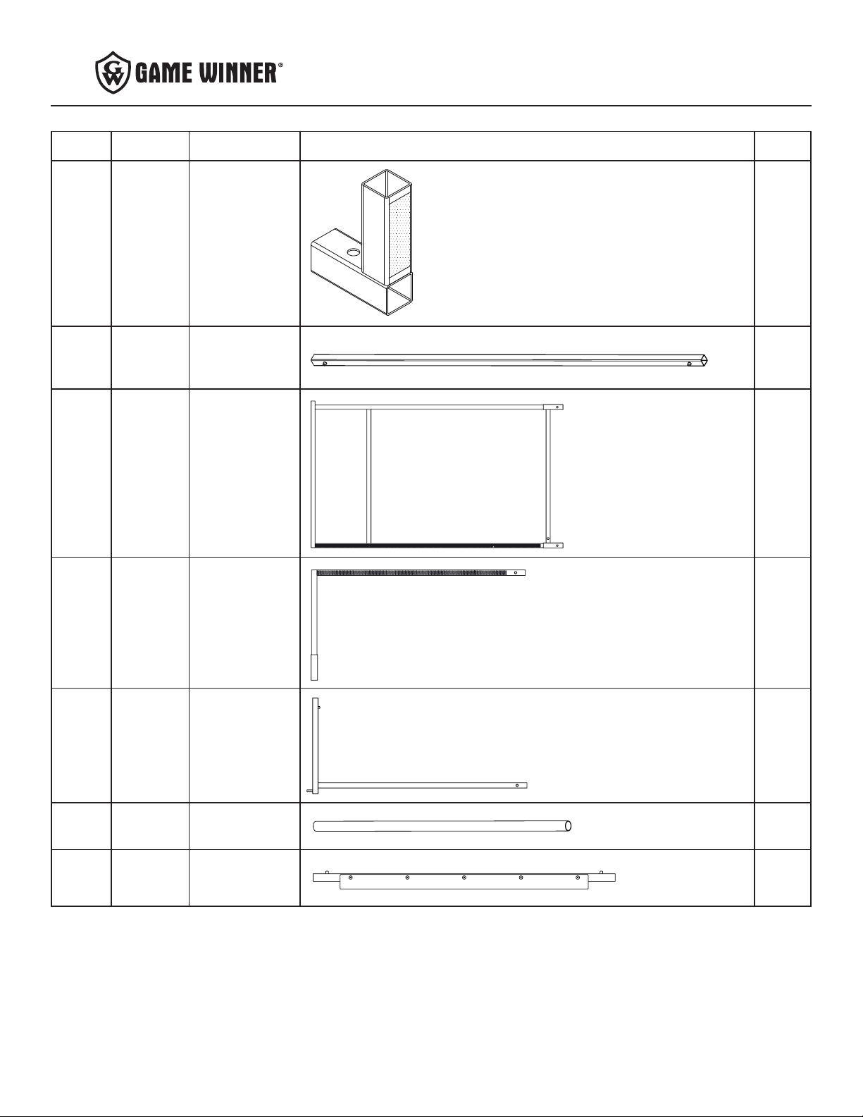
Parts List..................................................................................................................................................................................................................................4-9
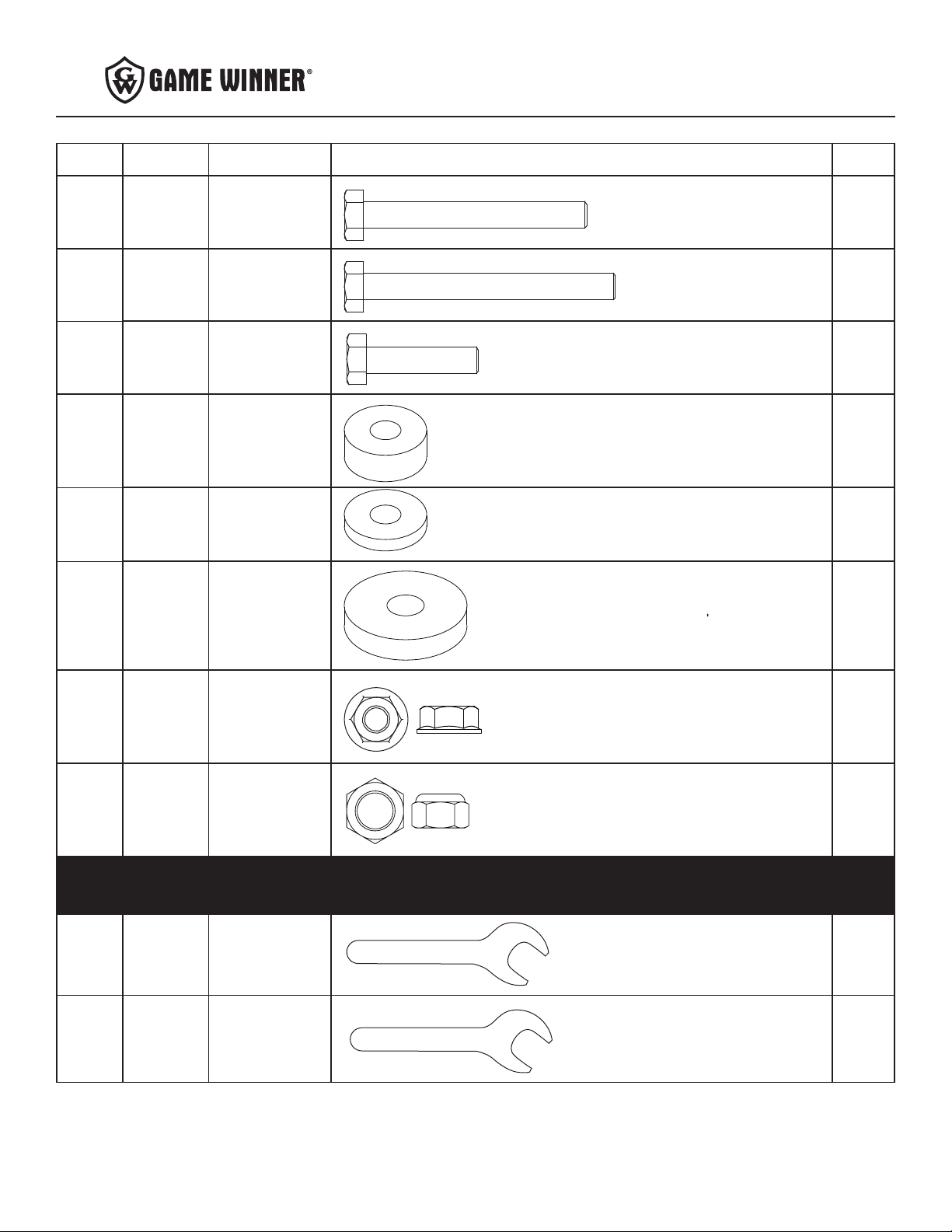
Hardware/Small Parts List...............................................................................................................................................................................................9-10
Tools Required........................................................................................................................................................................................................................10
Product Diagrams........................................................................................................................................................................................................... 11-14
Assembly Instructions .................................................................................................................................................................................................. 15-25
Notes................................................................................................................................................................................................................................... 26-27
Note: Before beginning assembly of product, make sure all parts are present. Compare parts list with package and
hardware contents. If any part is missing or damaged do not attempt to assemble the unit. Contact customer service
for replacement parts.
WARRANTY
Ardisam, Inc., warrants this product under a one-year limited warranty to be free from defects in materials or workmanship or both for a period not
exceeding twelve consecutive months from the date of original purchase by the rst retail consumer or commercial end user. “Consumer use”means
personal recreational use by a retail consumer. “Commercial use”or “commercial application” means all other uses, including use for commercial, income
producing or rental purposes. Once a product has experienced commercial use, it shall thereafter be considered as a commercial use product for purposes
of this warranty. This warranty does not cover cracked windows, tent tears, or bent poles due to use in exteme weather conditions (i.e. hurricane force
winds) or uses other than those listed in the owner’s manual. Damage that occurs to a unit due to improper anchoring is not covered under manufacturer
warranty. This warranty applies to the original owner that provides a proof of purchase of the unit. The warranty is not transferable. The warranty period
begins on the date of purchase by the rst retail consumer or commercial end user, and continues for the twelve month consecutive period thereafter. Any
unit used in a commercial application is covered for a period of 90 days after purchase. For the warranty to be valid, the product must be registered online
at huntriversedge.com, within 30 days of purchase. Ardisam, Inc. shall not be obligated to ship any repair or replacement product to any location outside of
the United States of America or Canada.
This warranty applies only to products which have not been subjected to negligent use, misuse, uses other than those indicated in the product’s owner’s manual,
alteration, accident, use of unauthorized parts, failure to perform periodic maintenance as specied in product’s owner’s manual, or normal wear and tear. There
is no other expressed warranty. Implied warranties, including those of merchantability and tness for a particular purpose, are limited to one year from purchase,
or to the extent permitted by law. All other implied warranties are excluded. Liability for incidental or consequential damages are excluded to the extent exclusion
is permitted by law. Ardisam, Inc. does not assume, and does not authorize any other person to assume for us, any liability in connection with the sale of our
products. To obtain warranty service, you must have prior approval by calling our Customer Service Department at 1-800-345-6007. Ardisam, Inc. will at no charge,
repair or replace, at their discretion, any defective part which satises all conditions stated above. Ardisam, Inc. retains the right to change models, specications
and price without notice. Ardisam, Inc. shall not be obligated to ship any repair or replacement product to any location outside of the United States of America or
Canada.
If you choose to elevate this product to use above ground (on a tower type structure), only use Ardisam, Inc. original designed structures to do so. *Using manmade
structures or structures not manufactured by Ardisam, Inc. will void your warranty and waive any and all claims for liability against the manufacturer Ardisam,
Inc. If you choose to elevate this product on a Ardisam, Inc. brand tower structure, the warranty listed in the tower structure manual will apply to this product in
addition to the warranty statement in this owner’s manual.
PAGE