Game Winner PL701GW User manual

Instruction Manual
QUAD-POD 2.0 ACCESSORY KIT
MODEL #: PL701GW
STYLE #: 159105
For parts call our Customer Service Center at 800-450-3343
Business Hours: 8:00 am to 5:00 pm CST | info@huntriversedge.com
© 2019 RETI All Rights Reserved | 32348 REV3: 03/12/19
GAS/OIL
RATIO
50:1
PARTICIPATING MEMBER
PRODUCT MEETS
INDUSTRY STANDARDS
RECOGNIZED BY

Instruction Manual : QUAD-POD 2.0 ACCESSORY KIT
2
TABLE OF CONTENTS
Warranty Information ............................................................................................................................................................................................................2
Warnings.....................................................................................................................................................................................................................................3
Parts List......................................................................................................................................................................................................................................4
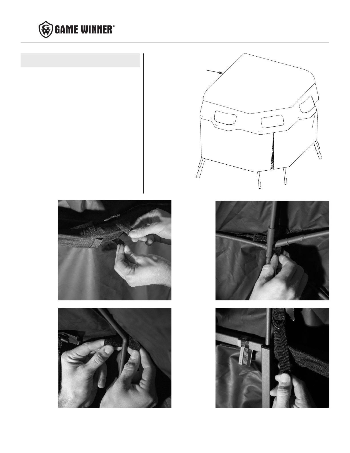
Assembly Instructions ....................................................................................................................................................................................................... 5-7
Note: Before beginning assembly of product, make sure all parts are present. Compare parts list with package and hardware
contents. If any part is missing or damaged do not attempt to assemble the unit. Contact customer service for replacement
parts.
WARRANTY
RETI oers a one year warranty for all components of the treestand. These warranties apply to the original owner with a proof of purchase. These warranties
begin on the date of purchase by the rst retail consumer and continue for the period specied above. These warranties apply to products that are not modied,
abused or used in a manner that deviates from the product’s intended usage. Minor fading in color is normal and is not covered by warranty. Any corrosion
of painted surfaces that occurs as a result of paint being removed or damaged is also not covered by warranty. RETI oers no other warranty expressed or
implied. Products for which warranty work has been approved must be sent directly to RETI and performed by RETI. To obtain warranty service and/or
replacement instructions, you must obtain prior approval from RETI before shipping your package to us by calling our customer service department
at 800-450-3343 or by writing to: RETI, P.O. Box 755, 1160 Eighth Avenue, Cumberland, WI 54829 for a return material authorization number (RMA#).
All items must be shipped prepaid. RETI will, at no charge, repair or replace, in RETI’s sole discretion, any product that satises the conditions stated above.
RETI retains the right to change models, specications and price without notice.
This equipment has been manufactured under strict quality and safety guidelines. As with any equipment of this type, full understanding of the instructions and
its use is mandatory and imperative for the safety of its user. RETI is not responsible for any damages or injuries sustained due to improper use or modication
of any of its products, or resulting from any use which deviates from the product’s intended usage. RETI is not responsible for any injuries sustained due to
failure to read and adhere to the instructions for use. Any misunderstanding or questions regarding the products of their use should be directed to RETI prior
to any use. It is the owner’s sole responsibility to inspect the product regularly for damage, improper installation, or conditions that could jeopardize the
ultimate safety of the product. Owner is responsible to understand and follow product eld weight rating and must never exceed maximum weight
rating. RETI is not responsible for any malfunction or injury resulting from normal wear and tear, damage caused by improper use, improper maintenance,
negligence or accidents. This product, if used safely as intended, will provide trouble free service for the useful life of the product. We hope you will enjoy the
quality of our products for years to come, and have a safe hunt.
PAGE

Instruction Manual : QUAD-POD 2.0 ACCESSORY KIT
3
WARNING
When hunting from a treestand falls can occur any time
after leaving the ground causing injury or death.
Read and understand all of the manufacturer’s Warnings
and Instructions and use all safety devices provided by the
manufacturer. Contact the manufacturer for any questions.
Failure to do so could result in injury or death.
Never allow the material to cover your face. This material can
cause suocation and death if it is placed over face.
Never allow children to play in this product.
Only use approved RETI parts. Failure to do so may result in
serious injury or death!
Never modify in any way by making repairs, replacing parts,
or altering it except if explicitly authorized in writing by the
manufacturer.
WARNING
Assemble this accessory kit to Quad-Pod 2.0 tower at
ground level before attaching the legs.
Ultraviolet light breaks down lightweight fabric bers. The
material will fade, lose strength and eventually disintegrate if
left in prolonged sunlight. To extend the life of your blind,
avoid leaving it out in direct sunlight for extended periods
of time. Set it up in a shady area whenever possible. Fading or
discoloring of blind is not covered under your warranty.
Double check assembly steps to be certain you have correctly
assembled this product.
Keep all ame and heat sources away from this fabric.
This product is not reproof. The fabric will burn if left in
continuous contact with a ame source.
Heat sources burn oxygen and emit carbon monoxide. Use
caution with heaters and vent properly.
READ AND UNDERSTAND THE FOLLOWING WARNINGS BEFORE ASSEMBLY
STOP

Instruction Manual : QUAD-POD 2.0 ACCESSORY KIT
4
PARTS LIST
Item Part No. Description Image Qty
1 # 32216 SEWN CURTAIN 1
2 # 32217 SEWN ROOF 1
3 # 32325 SPLIT SUPPORT
POLE 1
4 #32326
SPLIT SUPPORT
POLE WITH
POCKET
2
5 #32327 SUPPORT POLE
WITH NO POCKET 1
6 # 32328 SUPPORT POLE
WITH POCKET 1

Instruction Manual : QUAD-POD 2.0 ACCESSORY KIT
5
ASSEMBLY INSTRUCTIONS
NOTE: Assemble this accessory kit to Game Winner Quad-Pod
2.0 at ground level before attaching legs.
1. Slide the pocket end of the two split support poles with
pockets (4) onto the split support pole (3). SEE FIGURE 1.
Slide the split support pole (3) into the plastic insert on
the shooting rail in the corner of the blind opposite the
entry opening. SEE FIGURE 1 AND FIGURE 1A.
Then, slide the two split support poles with pockets (4)
into the plastic inserts on both sides of the entry opening.
SEE FIGURE 1 AND FIGURE 1A.
FIGURE 1
FIGURE 1A
FIGURE 2
STEP 1
STEP 2
2. Slide the pocket end of the support pole with pocket (6)
onto the support pole with no pocket (5). SEE FIGURE 2.
Slide each support pole (5, 6) into the remaining plastic
inserts on the shooting rail. SEE FIGURE 2 AND FIGURE
1A.
5
6
4
3
3
PLASTIC
INSERT

Instruction Manual : QUAD-POD 2.0 ACCESSORY KIT
6
3. Attach the curtain (1) to the quad-pod frame by aligning
the zipper to the center of the entry opening. Begin
securing it by attaching the top edge by wrapping the
hook and loop strips around the shooting rail. SEE FIGURE
3A. Work your way around the shooting rail and back to
the zipper. Make adjustments as needed. SEE FIGURE 3.
Attach the bottom edge of the curtain to the platform
by tying the webbing strips to the outer perimeter of the
platform. SEE FIGURE 3B.
STEP 3
FIGURE 3
FIGURE 3A
1
ZIPPER
FIGURE 3B

Instruction Manual : QUAD-POD 2.0 ACCESSORY KIT
7
4. Attach the roof (2) to the quad-pod and roof frame by
draping it over the top of the assembled frame and adjust
until the corners are lined up with the roof poles. SEE
FIGURE 4.
Begin securing it by attaching the bottom edge to the
shooting rail by wrapping the hook and loop strips around
it. SEE FIGURE 4A.
Next, attach the center of the roof to the roof poles where
they intersect in the middle with the hook and loop strip.
SEE FIGURE 4B.
Then, attach each corner of the roof to each corner of the
roof poles by wrapping the hook and loop strips around
the roof poles near each corner bend. SEE FIGURE 4C.
Lastly, tension the roof by wrapping the ve d-ring straps
around the shooting rail and pulling tight. SEE FIGURE
4D.
NOTE: Do not over tension. Only take the slack out of the
panel.
STEP 4
FIGURE 4
2
FIGURE 4A
FIGURE 4C
FIGURE 4B
FIGURE 4D

*All weights, specications and features are approximate and are subject to change without notice. Due to continuous product improvements, product images may not be exact. Warning labels in some product
images may have been removed for photography purposes only. Props shown in photos not included. Some assembly may be required.
This manual suits for next models
1
Table of contents
Other Game Winner Tent manuals