Gammex 403 LE User manual

403 LE
Precision
Multi-Purpose
Phantoms
User’s Guide

2
Table of Contents
Introduction....................................................................................3
Caring for your 403 LE..................................................................4
Scanning the 403 LE.....................................................................5
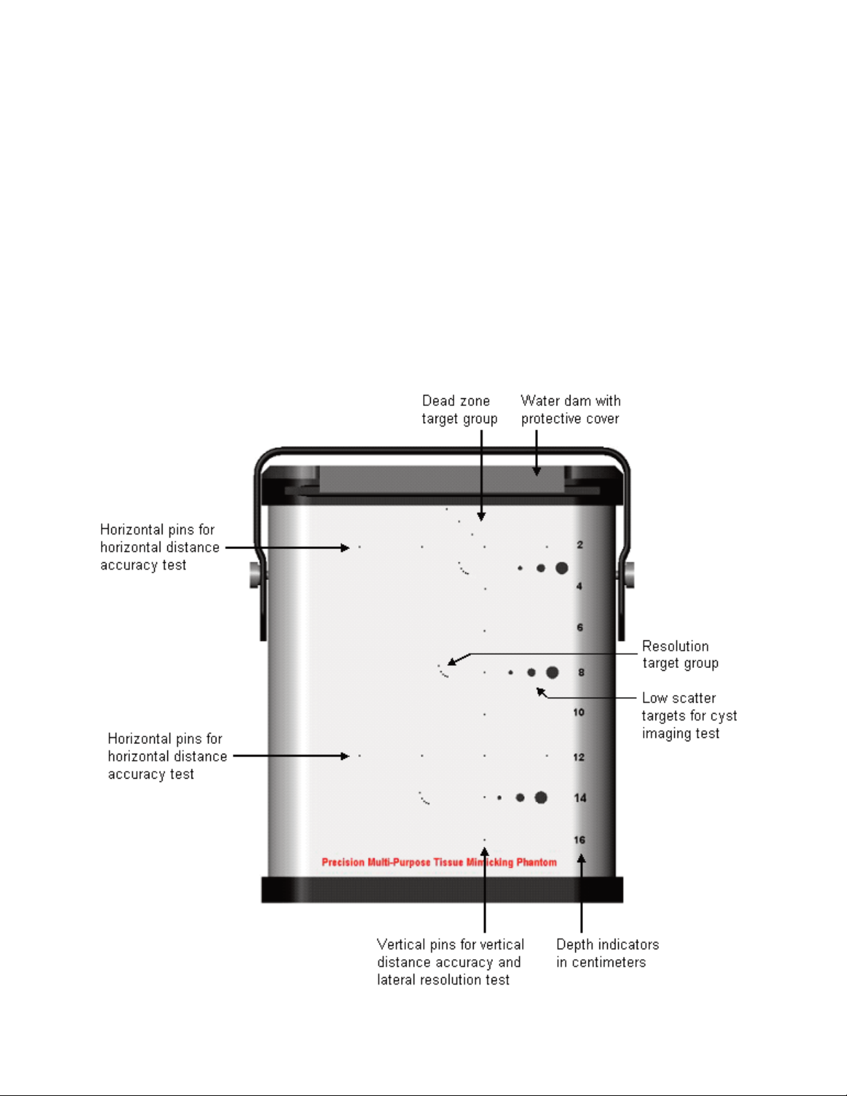
A Guided Tour of the 403 LE........................................................6
Evaluating the Phantom..................................................................7
Target Specifications..................................................................11
Cystic Targets................................................................................11
Pin Targets....................................................................................11
Resolution Target Groups...................................................................11
Phantom Specifications.............................................................13
Physical Specifications.................................................................13
Tissue Mimicking Background Material........................................13
Low Scatter (Anechoic) Cysts.......................................................13
Harmonic Imaging.......................................................................14
Phantom Desiccation...................................................................15
Charts and Graphs.........................................................................15
Product Warranty.........................................................................16
Sales and Service........................................................................17

3
Introduction
The 403 LE phantom is designed to evaluate the image quality of high resolution
ultrasound systems. The phantom offers carefully placed targets to measure resolution,
depth of penetration, and electronic caliper distance accuracy. Axial resolution pin
spacing patterns are small, offering better axial resolution tests.
Target depths of the phantom extend to 16 cm. This provides a greater ability to test the
resolution capability of the scanner and transducer, as well as electronic caliper
measurement. Pin targets have been included to allow for testing high frequency
transducers that are designed to image the first few centimeters of tissue.
The phantom uses the latest technology in tissue mimicking gel which provides a very
smooth background texture. The composite film scanning surface has been developed
to allow more of the ultrasonic beam to be transmitted and received. The phantom is
fully compatible with the latest tissue harmonics equipment and technology.
Limitations of Use
The 403 LE is designed to be used to aid in the Quality Control testing and monitoring
of ultrasound instruments only. The 403 LE is not to be used to make diagnostic deci-
sions.

4
Caring for your 403 LE
Phantom comes ready to scan. Do not remove surface material.
Store the 403 LE with cover closed securely.
Always attach the scanning surface cover and store the phantom out of direct sunlight
when it is not in use. Store in the plastic bag that is provided or in an air and water-tight
container.
Store the 403 LE at 35º –105ºF (2º–40ºC).
Freezing temperatures will damage the phantom and high temperatures will accelerate
desiccation.
Weigh the 403 LE to monitor desiccation.
Weigh the phantom when you first receive it and then every 6 months after that. Record
the values on the data sheet.
Do not drop or damage the phantom.
Return the phantom for inspection and/or repair if it has been dropped or damaged.
Physical damage to the case will cause premature desiccation.
Gammex recommends annual servicing of your 403 LE to ensure proper operation.
Our qualified service technicians will check for desiccation and provide any needed
rejuvenation, scanning/certification to original specifications, and repairs.

5
Scanning the 403 LE
• Always place the phantom on a stable, level surface for scanning.
•The phantom comes ready to scan. Do not peel off surface material.
• Use water or a generous amount of coupling gel to ensure good transmission. Do
not use mineral oil, baby oil or lanolin-based gels as a coupling medium. Poor
transmission is a result of insufficient coupling.
•Do not press the transducer into the scanning surface. This damages the
scanning surface and will shorten the life of the phantom. For curved
transducers, use water or a thick layer of gel.
• Clean the scanning surface immediately after use. Use a soft cloth or paper towel
and soap and water, if needed.
Caution:
Do not press the tranducer
into the scanning surface.

6
A Guided Tour of the 403 LE
The Tissue Mimicking Phantom 403 LE measures the image quality of ultrasound
scanning systems. The tissue mimicking gel in the 403 LE is ultrasonically similar to
human tissue. The speed of sound, attenuation, and the nonlinearity parameter (B/A)
all correspond very well to measured values seen in human tissue. These qualities give
the phantom its smooth appearance and allow the use of normal scanner control
settings, which mimic a realistic scanning situation that one might come across
clinically. This makes the 403 LE phantom an invaluable tool for training.
Scanning is the best way to familiarize yourself with the features and functions of the
403 LE. A guided tour of the phantom is provided on the following pages.

7
Evaluating the Phantom
Remember
A 4.5MHz probe will provide a good overall view of the phantom for this demonstration.
1. Turn the handle out of the way and slide the cover off the phantom.
2. To couple with water, fill the dam with distilled water. For a better image quality,
use gel.
3. Rest the transducer on the scanning surface. Adjust the scanner to display the
full depth of the phantom.
You may notice that the tissue echoes near the bottom of the phantom fade into
noise. The depth at which usable echoes disappear is called the depth of
penetration. The depth markers on the phantom label will help you determine
the depths of targets.
•The phantom comes ready to scan. Do not peel off surface
material.
•Never press the transducer into the scanning surface.
• Always clean and dry the scanning surface after each use. Never
leave coupling gel or water on the scanning surface for more than a
few hours.
•Do not use mineral oil, baby oil or lanolin-based gels as a coupling
medium.

8
4. Move the transducer across the scanning surface while observing the locations of
the targets.
Notice how the smooth texture of the tissue mimicking gel emphasizes image
non-uniformities and artifacts, making them easier to detect. Scanning an area
without targets is a good way to test for image uniformity.
Decrease gain controls to highlight pin targets.
5. Scan the vertical pin targets and freeze the image. Use the electronic calipers to
measure the distance between two of the vertical pin targets. Repeat for two of
the horizontal pin targets. The vertical pins have 2 cm spacing while the
horizontal pins have 3 cm spacing.
Use the pin targets to determine vertical distance accuracy and horizontal
distance accuracy. Note that the highest dead zone pin you can see should be
the point of reference not the scanning surface.
6. Freeze an image of the vertical pin targets. Use the electronic calipers to
measure the horizontal width of the pin targets in the near, mid and far fields of
the image.
Notice how the pin targets are narrowest in the focal zone. The pin width
demonstrates the width of the ultrasound beam at that depth and approximates
the lateral resolution of the scanner.
Measure pin width
to get lateral
resolution.
Pin targets are
narrowest in the
focal zone.

9
7. Decrease the image depth and examine the axial resolution target group at 3 cm.
Notice how the images of the lower pin targets may begin to merge. The smallest
distance between two pins that can be clearly resolved with no vertical overlap is
called the scanner’s axial resolution.
Pin targets are resolved axially if an imaginary horizontal line can be drawn
between the targets without touching either target. The targets on the left are not
resolved. The targets on the right are resolved.
Examine the other axial resolution target groups and compare the resolution at
various depths. Axial resolution may decrease with depth.
Unresolved Resolved

10
8. Scan the nearest cystic target group. Each target should be round with a clean
black appearance and well defined edges. Bright specular echoes at the top and
bottom of the targets are normal.
Measure the dimensions of the 6 mm cystic target to check the image geometry.
Use calipers to measure from top to bottom and side to side. Repeat with the
other cystic target groups as part of the cyst imaging test.
9. Decrease image depth to the minimum and examine the dead zone target group.
The dead zone targets can also be used to measure lateral resolution in the
extreme near field of the transducer.
Note: The highest dead zone pin you can see should be the point of
reference for all measurements – not the scanning surface.
10. When you are done scanning the phantom, empty the water dam or completely
clean off the coupling gel with a soft cloth or paper towel. Replace the cover and
secure by lifting the handle to protect the phantom.

11
Target Specifications
Cystic Targets
Diameters............................................................................2, 4, and 6 mm
Placement.................................................................3, 8, and 14 cm deep
Pin Targets
Diameter...........................................................................................0.1 mm
Vertical spacing....................................................10 mm at 2 to 4 cm deep
.................................................................20 mm at 4 to 16 cm deep
Horizontal spacing...........................................30 mm at 2 and 12 cm deep
..................................additional pin spaced at 10 mm in shallow set
Resolution Target Group
.........................................................................3, 8, and 14 cm deep
All acoustic measurements made at 4.5 MHz, 22ºC.
Due to our philosophy of continuous quality improvement,
all specifications are subject to change.

12

13
Phantom Specifications
Physical Specifications
Weight..................................................................Approx. 2.8 kg (6 lbs. 5 oz.)
Dimensions....................................................................23.2 x 8.25 x 18.5 cm
...........................................................................(9.25 x 3.25 x 7.25 in.)
Case material..................................................................extruded ABS plastic
Pin target material............................................................Nylon monofilament
Scanning surface......................................................................Composite film
Tissue Mimicking Background Material
Water-based gel with the appearance of human tissue.
Speed of sound...........................................................................1540±10 m/s
Temperature dependence on speed of sound.................................1.5 m/s/ºC
Attenuation coefficient................................................... 0.7±0.05 dB/cm/MHz
............................................................................0.5±0.05 dB/cm/MHz
.................................................................(refer to phantom side label)
Nonlinearity parameter (B/A)................................................................6.6±0.3
.........................................6.7 (Accepted value for human liver tissue)
Low Scatter (Anechoic) Cysts
Speed of sound...........................................................................1540±10 m/s
Temperature dependence on speed of sound..................................1.5m/s/ºC
Attenuation coefficient..................................................0.05±0.01 dB/cm/MHz
All acoustic measurements made at 4.5 MHz, 22ºC
Due to our philosophy of continuous quality improvement,
all specifications are subject to change.

14
Harmonic Imaging
Harmonic imaging has become an important addition to the medical ultrasound commu-
nity. Harmonic imaging is when a pulse is sent from the transducer at a nominal (funda-
mental) frequency, but the signal received by the transducer is twice that frequency,
which is the second harmonic. The result is that better resolution is attained at any given
depth than if the reception had been at the fundamental frequency, as in conventional
ultrasound.
There are three tissue properties that determine the effectiveness of harmonic imaging:
1. pulse propagation speed
2. attenuation (rate of pulse energy loss with depth)
3. the value of the nonlinearity parameter: B/A
In order for phantoms to present valid resolution results for harmonic imaging, these
three properties must adequately correspond to human tissue. Attenuation increases
with frequency and much of the propagation involves the fundamental frequency, so in
harmonic imaging, there is enhanced resolution without as much attenuation as there
would be if the higher frequency were used to generate the pulses at the transducer. So,
higher frequency resolution occurs for greater depths within the subject than if conven-
tional ultrasound was used.
The ratio of B/A quantifies the rate of transfer with respect to propagation distance of ul-
trasonic fundamental frequency energy to harmonic frequencies. The greater the ampli-
tude, the greater the energy transfer rate; thus, the beam profile for the harmonic is
smaller than for the fundamental, which means better lateral and elevational resolution.
Tissue-mimicking phantoms will be appropriate for assessing harmonic imaging only if
B/A for the tissue-mimicking material in the phantom adequately approximates that of
soft tissues. Recently, we have developed the capacity to measure the value of B/A for
the tissue-mimicking materials in Gammex phantoms and have found it to lie in the
range for human soft tissue, meaning B/A is between 6 and 71.
___________________________________________
1Gong, X. F., Zhu, Z. M., Shi, T., Huang, J. H. (1989) Determination of the acoustic non-
linearity parameter in biological media using FAIS and ITD methods, J. Acoust. Soc. Am.
86 (1), pp 1-5.

15
Phantom Desiccation
Over time, the phantom’s water-based gel will slowly lose moisture. This process is ac-
celerated by high temperatures, incorrect storage, and damage to the case or scanning
surface. Consistently storing the phantom in an air-tight container will contribute greatly
to long phantom life. A properly stored phantom will reduce the amount of moisture lost
per year.
For most climate-controlled environments, the phantom weight should be checked
every six months. Phantoms used in high temperature/low humidity environments or in
mobile situations should be tested more frequently. As the phantom desiccates, the
scanning surface may flatten out. It is suggested that the phantom be sent in for rejuve-
nation once it has lost 15 grams of its total weight. When this occurs, contact GAMMEX
(1-800-GAMMEX-1).
Charts and Graphs
Refer to the Charts and Graphs section of the manual to find the appropriate charts
and graphs for your 403 LE phantom, which include:
Phantom Weight Chart
Data Sheet

16
Product Warranty
WARRANTY, DISCLAIMERS AND LIMITATION OF LIABILITY:
The Products are covered by the warranty set forth in the following paragraphs. The warranty is
extended only to the purchaser of the Products directly from Seller (or an authorized dealer of
Seller) as new merchandise. For a period of twelve (12) months from the date of original deliv-
ery to Buyer, the Products are warranted to be free from functional defects in materials and
workmanship, provided they are operated under condition of normal use, and that repairs and
replacements are made in accordance herewith. Seller does not warrant bulbs. The foregoing
warranty shall not apply to Products that have been disassembled, altered or repaired (other
than proper replacement bulbs) other than by Seller or if the Product has been subject to abuse,
misuse, negligence or accident.
Seller’s sole and exclusive warranty obligation and Buyer’s sole and exclusive warranty consists
of Seller, at its option, repairing or replacing free or charge Products: (a) which contain a defect
covered by the above warranty; (b) which are reported in writing to Seller not later than seven
(7) days after the expiration of the warranty period; (c) which are returned to Seller promptly
after discovery of the defect; and (d) which are found to be defective by Seller upon Seller’s ex-
amination. Buyer shall pay all transportation charges. SELLER SHALL NOT BE OTHERWISE
LIABLE FOR ANY DAMAGES, INCLUDING BUT NOT LIMITED TO INCIDENTAL DAMAGES,
CONSEQUENTIAL DAMAGES, OR SPECIAL DAMAGES OR FOR ANY OTHER LOSS, DAM-
AGE, PENALTY OR EXPENSE OF ANY KIND, INCLUDING BUT NOT LIMITED TO, INCIDEN-
TAL DAMAGES, CONSEQUENTIAL DAMAGES, OR SPECIAL DAMAGES OR FOR ANY
OTHER LOSS, DAMAGE, PENALTY OR EXPENSE OF ANY KIND, INCLUDING, WITHOUT
LIMITATION, LOSS OF PROFITS OR OVERHEAD, REIMBURSEMENT, PERSONAL INJURY
OR PROPERTY DAMAGE. THE AFORESAID WARRANTY OBLIGATION OF SELLER CON-
STITUTES ITS SOLE LIABILITY, AND UNDER NO CIRCUMSTANCES, SHALL THE MAXIMUM
LIABILITY OF SELLER UNDER ANY LEGAL THEORY (e.g. CONTRACT, WARRANTY, NEGLI-
GENCE, PROMISSORY, ESTOPPEL, STRICT LIABILITY, MISREPRESENTATION, TORT)
AND FOR ANY REASON WHATSOEVER (e.g. DEFECT, DELAY OR OTHERWISE) EXCEED
THE PURCHASE PRICE OF THE DEFECTIVE PART, REGARDLESS WHETHER THE CLAIM
IS ASSERTED BY BUYER OR ANY OTHER PERSON OR ENTITY. THE LIABILITIES OF
SELLER, AS ABOVE SET FORTH, SHALL NOT BE EXTENDED BECAUSE OF ADVICE
GIVEN BY IT IN CONNECTION WITH THE DESIGN, INSTALLATION OR USE OF THE PROD-
UCTS OR PARTS THEREFOR.
THERE ARE NO EXPRESS OR IMPLIED WARRANTIES WHICH EXTEND BEYOND THE
WARRANTIES SET FORTH ABOVE. SELLER MAKE NO WARRANTY OF MERCHANTABIL-
ITY OR FITNESS FOR A PARTICULAR PURPOSE WITH RESPECT TO THE PRODUCTS OR
ANY PARTS THEREOF.
© 2003 GAMMEX- 007179-00-04
Your warranty may be registered at http://www.gammex.com/warranty.asp

17
Sales and Service
GAMMEX is committed to satisfying our customers’ needs. If you have any questions,
comments, or suggestions regarding our products and service, please call or fax us.
Sales Department hours are Monday through Friday, 7:30 am to 5:00 pm Central Time.
1-800-GAMMEX-1 (426-6391)
1-608-828-7000
1-608-828-7500 Fax
e-mail: [email protected]
Service Department hours are Monday through Friday, 7:30 am to 5:00 pm Central
Time.
1-800-232-9699
1-608-828-7000
1-608-828-7500 Fax
e-mail: [email protected]
GAMMEX, Inc.
7600 Discovery Drive
P.O. Box 620327
Middleton, WI 53562-0327 U.S.A.
http://www.gammex.com

18
Notes:

19
Notes:

Gammex, Inc.
P.O. Box 620327
Middleton, WI 53562-0327 USA
1 800 GAMMEX 1 (426-6391)
1 608 828 7000
Fax: 1 608 828 7500
www.gammex.com
e-mail: [email protected]
Gammex-RMI LTD
Broadway Business Centre
32A Stoney Street
Nottingham NG1 1LL
United Kingdom
+44 0115 9247188
Fax: +44 0115-9247189
e-mail: [email protected]
Gammex-RMI GMBH
Bergstrasse 2
35398 Giessen
Germany
+49 6403 774 2293
Fax: +49 6403 774 2526
e-mail: [email protected]
Table of contents
Other Gammex Test Equipment manuals