Gaoke BG9000 User manual

Guangzhou Gaoke Communications Technology Co.,LTD.
BG9000
User Manual

CONTENTS
1 Product Introduction
1.1 Hardware Interface
1.2 The Position of the Product in the Network
2 Configuration Introduction
3 Login WEB Administrator
4 WAN Configuration
5 Register IP Trunk Configuration
5.1 Registered Sever Configuration
5.2 Add IP Trunk Account
6 Extension Set Distribution and Configuration
6.1 Add Extension Account
6.2 IAD or SIP Account Assign and Registration
6.3 Extension Set Parameter Configuration
7 DID Configuration
8 DOD Configuration
9 call routing Configuration
10 Other commonly Used Configuration
10.1 IVR Configuration
10.2 Ringing Grouping Configuration
10.3 Figure Configuration
10.4 IVR、Color Ring Voice Document Management
10.5 SNMP Administrator Configuration
11 Equipment Maintenance
11.1 Reboot and Apply
11.2 Upgrade and parameter input and Output
11.3 Equipment Inner Packet Capture and Ping
11.4 Packet Capture by Port Image

1
1 Product Introduction
1.1Hardware Interface
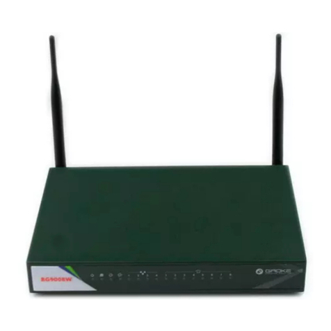
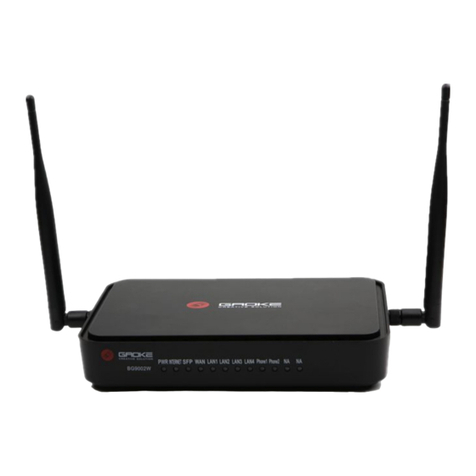
A new series of ALL IN ONE INTELLIGENT Gateway BG9000 is an integrated access
device, IAD, which integrate voip and data with the complete IPPBX, datarouting, farewall
and VPN features. Comparing with other Voice equipments, BG9008N has integrated high
data capacity of WIFI 300Mbps. Multi-access way of BG9000 has includes Ethernet, Optical
and 3G.
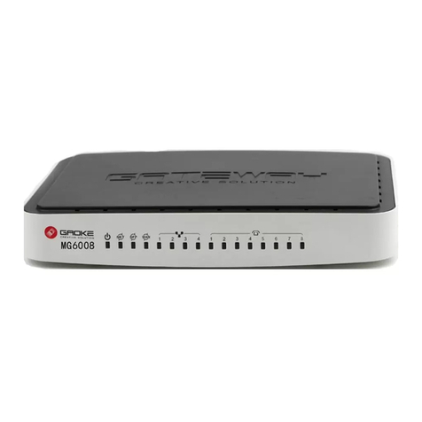
According the FXS/ FXO quantity, BG9000 has five versions, BG9002N, BG9004N,
BG9008N, BG9016N and BG9032N. Moreover, BG9004N has 2FXS+2 FXO configuration
and BG9008N has 2FXO,4FXO or 6FXO. Other interfaces are demonstrated in the chart.
LAN
4 100/1000BASE-T ports
WAN
1 FE ethernet port or 1 GE optical port
WIFI
4 WIFI access point, support 802.11b/g/n
SFP
1 Gigabit fiber interface
USB
1 USB 2.0 port, use for storage or 3G modem
Table 2-3 Hardware interface
The first LED light is power light, which will be on when the device power on. The second
light is operation light, which twinkles when it operates successfully. The operation light is on
and off second by second.
1.2 The Position of BG9000W in the Network

2
Figure 1 The Position of the Product in the Network
The position of BG9000 is demonstrated from the diagram above. It can register from IMS or
other Soft Switch System. The FXS interface can connect to the analog phone and FAX
machine. Moreover, it can distribute SIP account and register from IAD device.
2 Configuration Introduction
The steps of setting voice function:
1. Setting IP. IP address is providered by operator or customer.
2. Setting IP trunk account. IP trunk account information is offered by operator or customer.
3. Setting DID and DOD.
4. Setting call routing.
5. Other setting. SNMP administrator,IVR,ringing group, FXO configuration, etc.
Setting can be done through Quick Configuration Wizard. Using Quick Configuration Wizard
to set WAN, IP trunk, extension set distribution, DID, DOD and call routing configuration.
3. Login WEB Management

3
The Web interface is ready for accessing about one minute after the device power on. The
default LAN IP address is 192.168.100.1, you can access the Web interface via LAN port.
Enter IP address in the address bar of web browser and then press ENTER, you can get access
to the Login interface. The default account number and password are both “super”.
Figure 2 Login Interface
4. WAN Configuration
You should make sure the network is smoothly before you want to open the business of IP
PBX.The device’ WAN interfaces has 5 sub interface: DATA, VOICE, MGMT, OTHER1,
OTHER2; The way of sub interface to get the IP include :Static IP, DHCP, PPPoE, PPTP,
L2TP. You can open one or more interface and choose the way of getting IP address according
to your actual networking condition. Take an example, we use a most common mothed to
introduce the IP configuration--only setting the DATA sub interface.
you can choose the menu Network→WAN to load the configuration show page.Then click
DATA

4
Figure 3 WAN sub interfaces
Figure 4 WAN IP configuration
DATA sub interface has 5 ways to get the IP address.The most common way is:static IP,
DHCP and PPPoE.The detail connect method is provided by carrier or client.
5. Register IP Trunk Configuration
5.1 Registered Sever Configuration
Choose the menu quick configuration→Register IP Trunk→Registered Server or Sip Trunk
management→Register IP trunk→Register server, enter the register server configuration
page.The device has added a register server,click the server serial number and access into the
server configuration page. You can modify the configuration according to the real parameter
or add the parameter accourding the server’s real parameter.

5
Figure 5 Register Server configuration
Registering server should consider the actual conditions to choose backup server or proxy
server, as the operator’s IMS platform need to configure register server and proxy server. In
the example of figure 5, it just runs register server and proxy server. 172. 16. 0. 90.
5.2 Add IP Trunk Account
Choose the menu SIP Trunk→Register IP Trunk→IP trunk account or IP trunk
management→Register IP Trunk→Trunk account,click add access into the IP truck
configuration page.

6
Figure 6 Register IP trunk account configuration
IP trunk account, Authentication user name and password is provided by register server.It
much correct else the register will be failed.
Choose the menu SIP Trunk→Register IP Trunk→IP trunk account or IP trunk management
→Register IP Trunk→Trunk account,you can check the IP truck register status.
Figure 7 IP trunk register state
6. Extension Distribution and Configuration
6.1 Add Extension Account
BG9000’s extension account includes FXS and new added SIP user. The device has 2-32 FXS
users. If the user number is not enough, you can register from BG9000 through IAD device.
At this time, SIP account is needed. The existed extension set account can be seen by the
following steps. Manu==》extension management==》Account Assigned
Figure 8 is a BG9002N, which has two FXS accounts and no SIP account.

7
Figure 8 Extension Set Distribution Page
User can add, delete and modify accounts in this page. Choose the menu SIP Account→ SIP
Account Status to load the following page. If one equipment link with one device with 8
interfaces, it can add 8 SIP accounts. SIP account name is suggested to be English and number.
As it is shown in figure 9, it adds 8 SIP accounts, and the names are iad001 to iad008.
Figure 9
6.2 IAD or SIP Account assign and Registration
Adding SIP account needs other IAD or SIP phone register to BG9000 and it can be used
when the state is registered successfully. This part of configuration belongs to IAD or SIP
phone configuration. IAD or SIP phone has these configurations. (1) Connecting with IAD or
SIP phone need IP address to guarantee they can connect with LAN OR WAN. (2) Registered
server address is the IP address of BG9000 LAN or WAN. (3) Link with the IAD or SIP
phone need to set SIP account information including register account name,authorization and
password.
Choose Manu extension managemen==》extension status to check the extension state. You

8
can see the new added SIP account registration state. As shown in figure 10, 8 new added SIP
account was registered successfully in the IAD which IP is 192.168.100.101.
Sip account status
6.3 Extension Set Parameter Configuration
Choose Manu extension management== 》extension parameter, as to open the extension
configure page. In this page, any one extension can be configure or more at one time. In this
page, call routing, voice recording, forwarding can be set up. Moreover, the phone number of
extension can be configure. You will need to choose the extension set and click “amend in
batch”. Furthermore, the phone number can be changed in the extension set distribution page.
The extension set can call out only if its right is larger than the call routing right.
Choose the menu SIP Account→Account Parameter to load the following page.
The following items are displayed on this screen:
►Query: Search the interested accounts, which can be based on the account name, extension
number, registering status.
►Batch Edit: Configure multiple accounts at once for the same parameters. Select accounts,
on click
Batch Edit button to load the following page.

9
Extension parameter configuration
7. DID Configuration
How to connect IP trunk with extension sconfiguration? And when will it ring when IP trunk
call in? All these can be configure in DID page. All registered IP trunk and FXO will shown
in this page.
Choose menu quick configure==》DID or voice function management- DID. To get in the DID
configuration page and choose more than one trunk account to deal with the setting, also it
can be set up one by one. When setting one by one, click Edit and choose IP trunk ring
destination.
As it is shown in figure 12, when you call the first IP trunk, FXS1 700 extension set will ring.
When you call the second IP trunk, SIP iad001 8001 extension set will ring. When you call
the third IP trunk, you can hear IVR administrator’s welcome message. When you call the
fourth IP trunk, 82598983’s extension set will ring. When you call the fifth IP trunk, FXS2
701 extension set will ring.

10
DID configuration
As it is shown in the figure 12, the ring destination FXS1, FXS2, operator, call in extension set and SIP
account has to set up in the first place. One IP trunk can only set one ring destination.
8. DOD Configuration
The connection between IP trunk and the extension set is not only to find the ringing
destination from IP trunk, but also where to call out in the IP trunk. All these can be set in
DOD page. This page is shown in all the sub accounts.
Choose menu to set quickly==》
DOD or voice function management==》DOD to get in the
DOD configuration page or to configure in batch, or one by one. If you want to configure one
by one, you can click Edit, choose an available IP trunk. As it is shown in figure 13, 700
extension set can call out via using in the order of +862082598980 or +86208259898 this two
IP trunk. 701 extension set can call out from +862082598981 IP trunk and 8001 extension set
can call out from +862082598982 IP trunk.
DOD configuration
In the end, whether the extension set is allowed to call out from DOD page has to depend on the the right of
call out right or call routing setting.
9. Phone Router Configuration
After all the IP trunk register and exension register ,DID,DOD configuration.The extension
can be how to call out ad can occupy which IP truck to call out,that needs customer to
configurate the routing configurated according to the dial custom.
Choose the menu quick set==》call routing or voice function management==》call routing to
access into the call routing configuration page.You can see the device has default added three
direct dial number rote.We can modify or cancel these three routing and reconfigurate.The*
means number 0-9.Click add button,you can add the call routing.Shown in the figure14,it is a
0 as head routing,the nunber can be not fixed.This routing’s authorization is demostic(Only
call out right is larger or equal to the domestic long distand call extension,then it can allow
extension can call our from this call routing.That means it can dial any number which is 0 as
head.

11
Figure 14 call routing configuration
Figure 14 only add a dial policy(dia 0as head’s number),it need to choose the out call IP
truck for the dial which can match the rule.Shown as Figure 15
Figure 15 call routing IP trunk
There are several importan parameters in call routing”pier,routing authorization,IP trunk
name.”whether the extension can call out from IP tunk,it need these parameter to judge.
1、Whether the extension dial number can match the pier of call routing。
2、Extension of permissions is greater than or equal to the pier corresponding routing
routing permissions。
3、The trunk account which choose in Extension’s DOD configuration is included in the relay
parameters defined in the server name.
According to the document order, after the telephone routing configuration can be normal
for the phone call dial test。
10 Other commonly used Configuration
10.1 IVR Configuration
Built-in operator allows an enterprise or unit using unified foreign number, can play a
welcome speech, speech can be customized;Inbound built-in operator can dial 0 after entering

12
the human services, can also dial the other kin to different departments, also can directly dial
the extension number。Built-in operator can be configured in the following order:
(1) choose menu voice management==》build-in attendant==》basic configuration access
into the IVR configuration page and start the attendat,add build in attendant number.
Figure 16 Attendat configuration
(2)choose menu voice management==》build-in attendant==》basic configuration click
add button and access into the IVR configuration page.Shown as figure17 IVR menu
configuration.When inbound to the IVR listening to the popular language, according to the
zero extension after 700 will be ringing, press 1 inbound groups after the extension of the
8000 will be ringing, press 2 after ext 8001 will be ringing

13
Figure 17 IVR menu configuration
(3)In DID page configuration through which relay style, can be incoming to the built-in
operator 。The previous figure 12 DID configuration page displays from + 862082598982
trunk call in, you can call to the built-in operator。
10.2 Ringing grouping Configuration
Grouping ringing is a commonly used function, when to call a number, multiple
Numbers from vibration or vibration in a certain order, need to achieve by adding grouping
ringing。Grouping ringing device is the group in a number of outside type, and the paint type,
perimeter types are commonly used to following the inbound, namely for DID configuration
page or from the static IP relay incoming calls;Post type is generally used in internal cornet
call or for IVR configuration menu。
Choose menu voice business management== 》ring group open the ring group
configuration page.Figure 18 has showed the configuration has added two ring group.Ringing
for polling sequence,Click the extension number button can view the extension number are
included in group。The previous figure 12 DID configuration page displays from IP relay +
862082598983 trendy, grouping ringing here extension will be ringing in 82598983;Figure
17 IVR menu configuration page displays in front of the inbound to the IVR, press 1 after the
grouping ringing extension will be ringing in 8000.

14
Figure 18 ring group configuration
Figure Configuration
he destination number will be sent all in one time for SIP application, digitmap is used to
determine exactly when there are enough digits entered from the user to place a call. If the
number length of suited route item is fixed, the number will be sent when specified number of
digits is received; the call will be disconnected when inter-digit timeout expires.
Table 1-1 Digitmap Characters
Character
Description
0~9
Indicates specific digits in a telephone number expression.
X
Wildcard, matches any digit, excluding “#” and “*”.
*
Digit star
#
Digit pound
-
Connects the start and the end of a range
[]
Indicates the a range of numbers(not letters).
.
Matches an arbitrary number of occurrences of the
preceding digit, including 0.
|
Indicates a choice of matching expressions (OR).
T
Inter-digit timeout expires
S
Short timer expires, usually place at the middle of an
expression
Digitmap Example
8XXXXXXX|1[0-24]0|2[18].3|3XXSXX|[0-9*#][0-9*#][0-9*#].#|[0-9*#].T
“8XXXXXXX” denotes numbers start with 8, the length is 8.
“1[0-24]0” denotes numbers include 100, 110, 120 and 140.
“2[18].3” denotes numbers that start with 2 and end with 3, there can be arbitrary length of 1
or 8 after the first digit 2. 23, 213, 2183 is matched.
“3XXSXX” denotes numbers start with 3, the length can be 3 or 5. If the short timer configured
expires between the third digit and the fourth digit, the number will be sent.
“[0-9*#][0-9*#][0-9*#].#” denotes numbers end with #, and the length is no less than 2.
“[0-9*#].T” denotes any number that dialing time out.
Choose menu voice management==》FXO/FXS parameter management==》Figure into
figure configuration page ,Equipment configuration by default an idd call number 。If the

15
customer want to dial 9 out, just in front of the number of each figure rules add a 9。This
configuration number figure applies only to equipment FXS port。
IP account number figure on
the SIP terminal equipment configuration, such as in IAD, SIP configuration on the phone。
10.4 IVR、Color Ring Voice Document Management
Equipment have default IVR voice files, IVR, waiting for the sound file, keep the sound
files and file.Voice management==》voice file configuration page you can input or modify the
voice file,shown as figure 19.IVR voice is inbound to the IVR after heard of popular
language;IVR waiting for the sound is inbound to call the switchboard after IVR 0 or after
extension, in front of the switchboard 0 or extension on calling sound,enable automatic
transfer at the front desk to hear the voice also is IVR waiting for the sound; Keep the sound
is take the fork in the process of calls to maintain sound
Figure 19 voice file input
Configuration only support one format audio file,it is Audio sampling size 8,Audio sampling
level 8KHz,mono,Audio formats PCM,WAV file.
Figure 20 Device voice file format

16
10.5 SNMPconfiguration
ANMP Administrator Configuration
SNMP network is advantageous to the batch of equipment management, including batch
update, batch configuration, and network management to hang under the router equipment,
convenient maintenance.If you have a network management station, equipment is best when
the installation is to enable SNMP. Choose Menu system maintance== 》SNMP access into
SNMP web configuration interface.Including IADMS network management station
address/domain is must configure parameters, equipment identified as to reflect the
configuration of the equipment using the customer property.As shown in figure 21 example,
IADMS 172.16.0.90 is network management station address, and the device on the network
site registered successfully, and the name BG9000_ceshi display on IADMS network
management
You can configure the SNMP parameters and view the registration status of SNMP.
Choose the
menu System→SNMP to load the following page
The following items are displayed on this screen:
► Register Enable: Check this box to enable SNMP register.
► Server Address or Domain: Enter the IP address or domain name of register server.
BG9002N User Manual
Page 106 of 133
► Server Port: Enter the port of Register Server.
► TRAP Message Interval: Set the sending interval between TRAP messages.
► Regional Identity: Set the identity of regional.
► Device Identifier: Set the identifier of device.
► Enable Double Register Server: Check this box to enable backup Register Server.
► Backup Server Address or Domain: Enter the IP Address or Domain Name of Backup
Register
Server.
► Backup Server Port: Enter the port of Backup Register Server.
► Registration Status: The status of registration. Read only.

17
Click the Save button when finished.
Click Refresh button to refresh the web page.
Figure 21 SNMP management configuration
11.Equipment Maintenance
11.1 Reboot and Apply
If you modify the equipment IP address, the new IP address will take effect after restart
the device, other configuration parameters just click the application can take effect. As shown
in figure 22.3.8.2.1 Application
Firmware upgrade via WEB interface is available. There are 2 steps to complete
firmware updating.
1) Choose menu “System Upgrade”, then select the right firmware file, click Upgrade,
wait a
few minutes for firmware downloading and programming.
2) Choose menu “System Reboot”, then click Reboot button to reset the device.

18
Figure 22
3.8.3 Reboot System
Choose menu“System Reboot”, then click Reboot button to reset the device.
11.2 Upgrade and parameter Leading in and out
Equipment in use process may be due to special needs or problems need to upgrade
version. Sometimes need parameter of equipment import and export.Choose the menu
System== 》System management into version upgrades and parameters of the import and
export of the page,Shown as Figure 23,The firmware part is to upgrade the software version,
import and export of parameter configuration section.
Choose the menu System→Backup/Restore to load the following page.
The following items are displayed on this screen:
► Backup Current Configurations: Save current parameters as customer default
parameters.
► Load Default Configurations: To reset to customer default parameters.
► Restore Factory Configurations: To reset to factory parameters.
Figure 23 version upgrade & import and export of parameter configuration section
11.3 Equipment inner packet capture and Ping
Choose menu “System Diagnostic Ping”, and then you can use Ping function to check
connectivity
Other manuals for BG9000
1
Table of contents
Other Gaoke Gateway manuals
Popular Gateway manuals by other brands

Aztech
Aztech DSL1215FUN(L) Speci?cations

ZyXEL Communications
ZyXEL Communications P-660HNU-F1 Quick start quide

NETGEAR
NETGEAR CG3000Dv2 user manual

Amit
Amit SDE852-00001 user manual

Weishaupt
Weishaupt WEM-KNX Installation and operating manual

Grandstream Networks
Grandstream Networks GXW42XX series user manual