GAPOSA QC09 User manual

1
Attenzione: per la sicurezza delle persone è importante seguire attentamente queste
istruzioni.
- Nel caso di dubbi sull’istallazione di questo prodotto, contattare un tecnico qualicato
- Non utilizzare l’apparecchio nel caso in cui siano necessarie delle riparazioni
- Staccare l’alimentazione durante l’istallazione o qualsiasi intervento sulla centralina
La centralina QC09, per il comando di tapparelle e tende da sole, è provvista di una ricevente radio
(434,15MHz) ed una uscita per una pulsantiera ed un anemometro. La scatola che la contiene è
compatta e stagna e l’antenna è interna.
DATI TECNICI
Alimentazione 230 VAC 50-60Hz Dimensioni 133X35X25mm
Potenza max. motore 500 W Peso 100g
Frequenza 434,15 MHz IP 55
Nella memoria della ricevente possono essere memorizzati no a 31 codici di identicazione di
altrettanti trasmettitori. La tapparella/tenda viene attivata attraverso un trasmettitore e/o un
pulsante esterno (del tipo normalmente aperto).
Nell’installazione si può prevedere anche un anemometro QCWS/QCWSRI/QCWSSRI (opzionale).
Tale accessorio, quando attivato, fa chiudere automaticamente la tenda in caso di vento forte.
La portata utile del trasmettitore è di 20 mt. In spazio chiuso e di 100 m. all’aperto.
La distanza massima tra l’anemometro e la QC09 è di 30 m.
ATTENZIONE Se l’installazione prevede più di una QC09 nello stasso locale, nella
fase della prima installazione sarà necessario alimentare una centrale alla volta per
evitare qualsiasi interferenza (perdita della programmazione o inversione del
senso di rotazione).
TRASMETTITORI
COMPATIBILI
IT_Centralina di comando con ricevitore radio integrato................................ p. 1
EN_Remote Control Unit for shutters and awnings.......................................... p. 5
FR_Système de commande à distance pour volets roulants et stores.............. p. 9
DE_Steuergerät mit integriertem Funkempfänger........................................... p. 13
ES_Cuadro de mando con receptor radio integrado......................................... p. 17
QC09
QCTD QCT6 QCT1
QCT3S QCT34S
230 Vac - 50/60 Hz

2
COLLEGAMENTO ELETTRICO
Controllare che la tensione di rete disponibile sull’impianto sia quella indicata sull’etichetta.
I collegamenti della QC09 devono essere eseguiti da tecnici qualicati in grado di operare nel rispetto
delle norme. Una volta eseguito il cablaggio va messa la relativa vite di chiusura sul coperchio.
ATTENZIONE! La QC09 presenta due aperture sul tappo per un cavi elettrici di diametro
6.5/8mm. Se il diametro è troppo piccolo si perde la protezione IP55.
Per una maggiore portezione da agenti atmosferici, si consiglia l’installazione in verticale con l’uscita dei
cavi rivolta verso il basso.
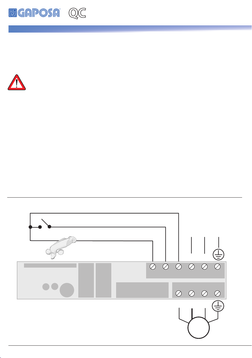
SCHEMA DI COLLEGAMENTO
QC09 Centralina di comando con ricevitore radio integrato.
230V~ 50Hz
ALIMENTAZIONE
M
N
C
M1 M2
F
654321
78910
SS_PULSANTE
COM_COMUNE
WND_ANEMOMETRO

3
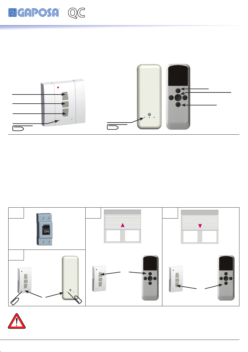
MEMORIZZAZIONE DEL PRIMO TRASMETTITORE
Il primo trasmettitore è chiamato MASTER ed è il solo a poter attivare la fase di programmazione.
MEMORIZZAZIONE
1. Alimentate il motoriduttore
2. Tenete premuto il tasto PROG-TX del trasmettitore nchè il motoriduttore non inizia a muoversi.
3. Controllate il senso di rotazione del motoriduttore - come nell’esempio la SALITA - rilasciate il tasto
PROG-TX ed entro 5 secondi premete il tasto SALITA del trasmettitore.
4. Se, al contrario, premendo il tasto PROG-TX il senso di rotazione fosse la DISCESA, rilasciate il
pulsante PROG-TX e premete entro 5 secondi il pulsante DISCESA del trasmettitore. In questo
modo avrete memorizzato il trasmettitore come MASTER e sincronizzato il senso di rotazione del
motoriduttore.
A questo punto, per vericare che il sistema funzioni correttamente, basta premere uno dei due pulsanti
SALITA o DISCESA del trasmettitore ed arrestare il motoriduttore con lo STOP.
IMPORTANTE: Il motoriduttore ruoterà in un verso o nell’altro per tutto il tempo che si
manterrà premuto il pulsante PROG-TX. Ogni volta che si rilascerà il pulsante
PROG-TX e lo si ripremerà nuovamente, il motoriduttore ruoterà nel senso opposto
(funzionamento sequenziale).
SALITA
DISCESA
PROG-TX
1
2
3 4
PROG-TX
SALITA SALITA
STOP
STOP
PROG-TX
DISCESA
DISCESA
QC09 Centralina di comando con ricevitore radio integrato.

4
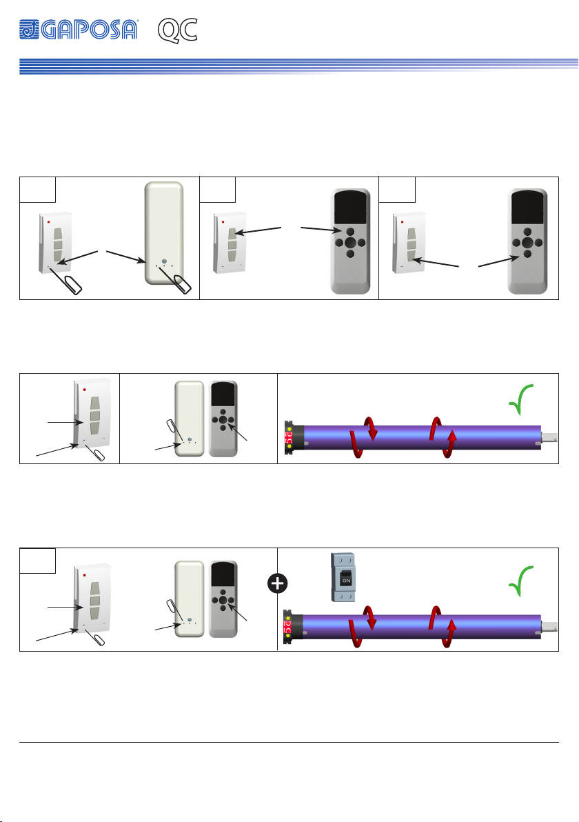
AGGIUNTA DI ALTRI TRASMETTITORI/CANALI
1. Premere il tasto PROG-TX del trasmettitore MASTER nchè il motoriduttore non inizia a muoversi. La
sua attivazione ci indica l’entrata in modalità programmazione del ricevitore integrato;
2. Controllare il senso di rotazione del motoriduttore quindi rilasciate il pulsante PROG-TX del
trasmettitore MASTER. In base alla direzione seguita dal motoriduttore premere entro 5 secondi
il tasto SALITA (g 2a) o DISCESA (g 2b) del nuovo trasmettitore da aggiungere. In questo modo si
aggiunge un nuovo trasmettitore nel ricevitore del motoriduttore.
CANCELLAZIONE
Per cancellare i codici memorizzati, occorre premere simultaneamente i pulsanti PROG-TX e STOP del
trasmettitore MASTER. Se il motoriduttore fa un piccolo movimento nei due sensi la procedura di can-
cellazione è stata compiuta correttamente.
CANCELLAZIONE SENZA TRASMETTITORE MASTER
Per cancellare i codici memorizzati in mancanza del trasmettitore MASTER:
1. Togliere l’alimentazione
2. Premere simultaneamente i pulsanti PROG-TX e STOP di un qualsiasi altro trasmettitore e alimentare
il motoriduttore. Se il motoriduttore fa un piccolo movimento nei due sensi la procedura di
cancellazione è stata compiuta correttamente.
SALITA
DISCESA
PROG-TX
1 2a 2b
STOP
PROG-TX
STOP
PROG-TX
2
PROG-TX
ON
STOP
PROG-TX
QC09 Centralina di comando con ricevitore radio integrato.
STOP
MASTER

5
IMPORTANT: READ CAREFULLY THESE INSTRUCTIONS
- In case of doubts about the installation, contact a qualied technician
- Disconnect supply during installation or whatever maintenance on the control
QC09 control unit for shutters and awnings is provided with a redio receiver (434,15MHz) and a
facility for a pushbutton and a wind sensor. It is in a water resistant box with an internal antenna.
TECHNICAL DATA
Power supply 230VAC 50-60Hz Dimensions 133X35X25mm
Max. motor power 500W Weight 100g
Frequency 434,15 MHz IP 55
The receiver can record up to 31 dierent codes to identify as many transmitters.
The shutter/awning is controlled by a transmitter and/or an external standard switch (normally
open). You can also install a wind sensor QCWS/QCWSRI/QCWSSRI (option) which closes the
awning automatically in case of strong wind.
The transmitter has a range of 20 mt. indoor and 100 m. outdoor.
Max. distance between wind sensor and QC09 is 30 m.
ATTENTION: If you install several QC09 in the same room, during the rst
installation you will have to supply and set each unit at a time in order to avoid
any interference (loss of programming or rotation inversion).
COMPATIBLE
TRANSMITTERS
Remote Control Unit for shutters and awnings
QC09
QCTD QCT6 QCT1
QCT3S QCT34S
6
ELECTRICAL CONNECTION
Check that the power supply corresponds to the label data. QC09 electrical connections must be
accomplished by electricians able to work in respect of the safety rules.
Once wiring accomplished, the cover must be xed with its screw.
WARNING! The QC09 has two openings in the cap for 6.5/8mm ø electrical wires. If the
diameter is too small the protection IP55 is lost.
For more protection when installed outdoor, we recommend installation in vertical with cables exit
facing downwards.
QC09 Remote Control Unit for shutters and awnings.
WIRING DIAGRAM
230V~ 50Hz
POWER SUPPLY
M
N
C
M1 M2
F
654321
78910
SS_SWITCH BUTTON
COM_COMMON
WND_WINDSENSOR
7
PROGRAMMING THE TRANSMITTER
The rst transmitter to be programmed is called MASTER and it is the only one by means of which you
can enter the programming mode.
PROGRAMMING PROCEDURE
1. Power the motor
2. Press and hold PROG-TX button of transmitter till the motor starts moving.
3. Check the motor direction (Ex. UP as shawn aside) then release the PROG-TX 5S button and
5 Sec within press the UP button of the transmitter.
4. If, on the contrary, pressing PROG-TX button the motor turns DOWNWARDS, release the PROG-TX
button and press the DOWN button of the transmitter within 5 Sec.
The MASTER transmitter is now programmed and the direction of the motor synchronized with the buttons
of the transmitter itself.
The MASTER transmitter is now programmed and the direction of the motor
synchronized with the buttons of the transmitter itself.
UP
DOWN
PROG-TX
1
2
3 4
PROG-TX
UP UP
STOP
STOP
PROG-TX
DOWN
DOWN
QC09 Remote Control Unit for shutters and awnings.
8
PROGRAM OTHER TRANSMITTERS
1. Press and hold PROG-TX button of the MASTER transmitter till the motor starts moving.
The motor is now in programming mode.
2. Press and hold PROG-TX button of the MASTER transmitter till the motor starts moving. The motor is
now in programming mode.
RESET MEMORY
To cancel transmitters from the motor’s memory, press PROG-TX and STOP buttons of the MASTER
transmitter simultaneously and release them when the motor jogs indicating that any transmitter is
cancelled.
RESET MEMORY WITHOUT THE MASTER TRANSMITTER
To cancel programmed transmitters without the MASTER:
1. Cut the power
2. Press simultaneously PROG-TX and STOP buttons of whatever transmitter and switch on the power
till the motor jogs indicating that any transmitter is cancelled.
UP
DOWN
PROG-TX
1 2a 2b
STOP
PROG-TX
STOP
PROG-TX
2
PROG-TX
ON
STOP
PROG-TX
QC09 Remote Control Unit for shutters and awnings.
STOP
MASTER

9
IMPORTANT! LIRE ATTENTIVEMENT CETTE NOTICE
- En cas de doutes sur l’installation de ce produit, appelez un technicien qualié
- Coupez l’alimentation pendant l’installation et toute intervention de maintient
de l’armoire
L’armoire QC09 pour la commande à distance de volets roulants et stores est pourvue d’un
recepteur radio (434,15MHz) et d’une sortie pour un inverseur et un capteur vent. Elle est placé en
une boîte étanche et pourvue d’une antenne interne.
DETAILS TECHNIQUES
Alimentation 230VAC 50-60Hz Dimensions 133X35X25mm
Puissance max. du moteur 500W Poids 100g
Frequence 434,15 MHz IP 55
Le récepteur accepte 31 codes diérents et donc 31 émetteurs.
Le volet/store est contrôlé par un émetteur et/ou un inverseur externe (type normalement ouvert).
Il est aussi prévue l’utilisation d’un capteur vent QCWS/QCWSRI/QCWSSRI (option) qui permet la
fermeture automatique du store en cas de vent fort.
L’émetteur à une portée de 20 m dans un espace fermé et de 300 m en espace libre.
La distance max. entre capteur vent et QC09 est de 30 m.
ATTENTION Si l’installation prévoit la présence de plusieurs QC09 dans la même
pièce, pendant la prémière installation il est necessaire d’alimenter une armoire à
la fois an d’éviter toutes interférences parmi les recepteurs (perte de la memoire
ou inversion du sens de rotation).
EMETTEURS
COMPATIBLES
Système de commande à distance pour volets roulants et stores.
QC09
QCTD QCT6 QCT1
QCT3S QCT34S

10
BRANCHEMENT ELECTRIQUE
Veriez que la tension d’alimentation disponible est celle indiquée sur l’etiquette. Les branchements de
la QC09 doivent être accomplis par des techniciens qualiés de façon à travailler conformement aux
normes.
Une fois le câblage réalisé, il faut mettre la vis de fermeture sur le couvercle.
ATTENTION ! La QC09 a deux ouvertures sur le couvercle pour câbles électriques de
6.5/8mm de diamètre. Si le diamètre est trop petit, la protection IP55 n’est plus garantie.
Pour une meilleure protection contre les intempéries, nous recommandons l’installation verticale de la
commande avec la sortie des câbles vers le bas.
QC09 Système de commande à distance pour volets roulants et stores.
BRANCHEMENT
230V~ 50Hz
ALIMENTATION
M
N
C
M1 M2
F
654321
78910
SS_BOUTON
COM_COMUN
WND_ANEMOMÈTRE
Table of contents
Languages:
Other GAPOSA Remote Control manuals


