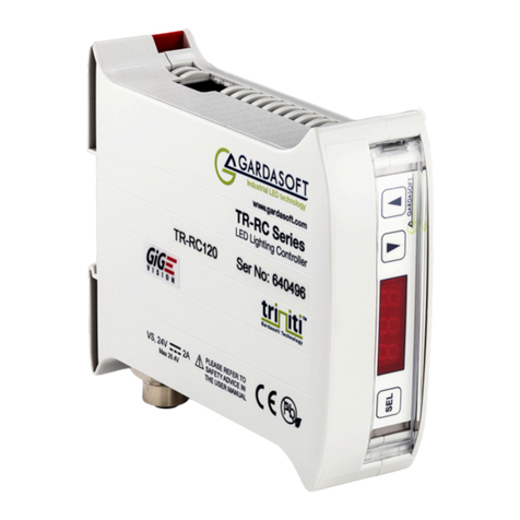
GARDASOFT TR-CL Series User manual

TR-CL180
Lens Controller
Issue 003
User manual
www.gardasoft.com
WWW.STEMMER-IMAGING.COM

TR-CL180 Lens Controller -User Manual
Copyright and disclaimer notice
Except as prohibited by law:
All hardware, software and documentation is provided on an ‘as is’ basis. This
information is for guidance only. Installers must perform their own risk assessment
specific to each installation.
It is essential that the users ensure that the operation of the product is suitable for
their application.
The users must ensure that incorrect functioning of this equipment cannot cause any
dangerous situation or significant financial loss to occur.
Deliberate acts of endangerment and vandalism are not covered by this document and
must be considered by the installer.
While care has been taken in the preparation of this document Gardasoft Vision Ltd will
not accept any liability for consequential loss of any kind except those required by law.
All trademarks acknowledged. Hardware, software and documentation are Copyright
2002 –2016 Gardasoft VisionLtd.
EC conformity declaration
The EC Certificate of Conformity is available from Gardasoft Vision Ltd on request
Issue status of this document: Issue 003 (January 2017)
TR-CL180 Lens Controller -User Manual
Contents
4Getting started 5
4.1 TR-CL180 features - a summary 5
4.2 GigE VisionTM 5
5Safety 6
5.1 Electrical 6
5.2 General 6
6Sicherheit 7
6.1 Elektrik 7
6.2 Allgemeines 7
7Sécurité 8
7.1 Électricité 8
7.2 Général 8
8Mounting the TR-CL180 9
8.1 Environmental considerations 9
9Connecting the TR-CL180 10
9.1 Power 10
9.2 Lens output 11
9.3 Trigger input 11
9.4 Ethernet 12
9.5 RS232 12
9.6 Connectors (general) 13
10 General description 14
10.1 Triggering 14
10.1.1 Trigger input options 15
10.2 Flags 16
10.3 Factory settings 17
11 Front panel commands 17
11.0.1 Startup 17
11.0.2 Setting up continuous optical power 18
11.0.3 Setting up switched output 19
11.0.4 Setting up analog control 20
11.0.5 Setting numerical values 20
11.0.6 Using the key lock 21
11.0.7 Viewing the output current 22
12 Ethernet address 23
12.1 IP address 23
12.1.1 DHCP 24
12.1.2 Fixed IP address 24
13 Webpage configuration 25
13.1 Main page 25
13.2 Configuration page 25
13.3 General setup page 26
14 Configuration commands 27
14.1 Ethernet configuration 27
14.2 RS232 configuration 27
WWW.STEMMER-IMAGING.COM

WWW.STEMMER-IMAGING.COM
TR-CL180 Lens Controller -User Manual
14.3 Command structure 27
14.4 General commands 29
14.5 Analog mode commands 32
14.6 Waveform commands 34
14.7 Programmable step commands 39
14.8 Command summary 41
15 TR-CL180 reference information 42
15.1 Specifications and ratings 42
15.2 Restrictions 43
15.3 Event codes 43
15.4 Error codes 44
WWW.STEMMER-IMAGING.COM

TR-CL180 Lens Controller -User Manual
14.3 Command structure 27
14.4 General commands 29
14.5 Analog mode commands 32
14.6 Waveform commands 34
14.7 Programmable step commands 39
14.8 Command summary 41
15 TR-CL180 reference information 42
15.1 Specifications and ratings 42
15.2 Restrictions 43
15.3 Event codes 43
15.4 Error codes 44
TR-CL180 Lens Controller -User Manual
4Getting started
Before you use this product, make sure that you have read and
understood Section 5, Safety (or Section 6, Sicherheit,or Section 7,
Sécurité)and Section 15.1, Specifications and ratings,and that you have
checked the TR-CL180 fulfils your requirements.
Mount the TR-CL180 (see Section 8, Mounting the TR-CL180)and
connect it up (see Section 9, Connecting the TR-CL180), as required.
Set up the TR-CL180 for the desired operation as described in Section
13, Webpage configuration or Section 14, Configuration commands.
We recommend that you visit www.gardasoft.com for application notes
on this product.
There is also asupport web page there, which has information on trouble-
shooting problems.
4.1 TR-CL180 features - a summary
The TR-CL180 product is asingle channel lens controller for use in
machine vision applications. It works with the following ranges of Optotune
lenses:
EL-10-30
EL-16-40
4.2 GigE VisionTM
The TR-CL180 is GigE Vision™ compatible. This means that any
compatible GigE Vision client image processing software (for example,
CVB, LabVIEW, Halcon) allows the user to view and change controller
settings. GigE Vision is an industry standard protocol running on Ethernet
which provides easy configuration and control of cameras and other
devices.
The TR-CL180 is the first non-streaming device to become available
(at the time of publishing this manual), so some packages may not support
non-streaming devices yet. If your package does not work with the
TR-CL180 then please inform the manufacturer or Gardasoft.
—5—
WWW.STEMMER-IMAGING.COM

WWW.STEMMER-IMAGING.COM
TR-CL180 Lens Controller -User Manual
5Safety
Read this before using the TR-CL180. Always observe the following safety
precautions. If in doubt, contact your distributor or Gardasoft Vision. The
following symbols mean:
Warning: Read instructions to understand possible hazard
Warning: Possible hazardous voltage.
Where these symbols appear in the manual, refer to the text for
precautions to be taken.
5.1 Electrical
The user must ensure that the potential difference between any
combination of applied signals does not exceed the supply voltage.
The TR-CL180 does not have complete tracking isolation of inputs and
outputs.
Transients caused by inductive loads must be suppressed externally to
the TR-CL180.
5.2 General
The TR-CL180 must not be used in an application where its failure could
cause adanger to personal health or damage to other equipment.
If the equipment is used in amanner not specified by the manufacturer,
the protection provided by the equipment may be impaired.
—6—
WWW.STEMMER-IMAGING.COM

TR-CL180 Lens Controller -User Manual
5Safety
Read this before using the TR-CL180. Always observe the following safety
precautions. If in doubt, contact your distributor or Gardasoft Vision. The
following symbols mean:
Warning: Read instructions to understand possible hazard
Warning: Possible hazardous voltage.
Where these symbols appear in the manual, refer to the text for
precautions to be taken.
5.1 Electrical
The user must ensure that the potential difference between any
combination of applied signals does not exceed the supply voltage.
The TR-CL180 does not have complete tracking isolation of inputs and
outputs.
Transients caused by inductive loads must be suppressed externally to
the TR-CL180.
5.2 General
The TR-CL180 must not be used in an application where its failure could
cause adanger to personal health or damage to other equipment.
If the equipment is used in amanner not specified by the manufacturer,
the protection provided by the equipment may be impaired.
—6—
TR-CL180 Lens Controller -User Manual
6Sicherheit
Bitte lesen Sie dieses Dokument, bevor Sie die TR-CL180 verwenden.
Beachten Sie immer die folgenden Sicherheitshinweise. Bei Fragen
wenden Sie sich an Ihren Händler oder an Gardasoft Vision. Die folgenden
Symbole bedeuten:
Warnung: Lesen Sie die Anleitung, um die mögliche
Gefahrenquelle zu verstehen.
Warnung: Mögliche gefährliche Spannung.
Wenn diese Symbole in der Anleitung erscheinen, finden Sie im
beistehenden Text die zu ergreifenden Vorsichtsmaßnahmen.
6.1 Elektrik
Der Benutzer muss sicherstellen, dass der Potenzialunterschied zwischen
jeder beliebigen Kombination an angelegten Signalen die
Versorgungsspannung nicht überschreitet.
Die TR-CL180 verfügt über keine vollständige Nachlauf-Isolierung der Ein-
und Ausgänge.
Spannungsspitzen am TR-CL180 aufgrund von induktiven Ladungen
müssen extern unterdrückt werden.
6.2 Allgemeines
Die TR-CL180 darf nicht in Bereichen verwendet werden, in denen bei
Ausfall eine Gefahr von Personen- oder Sachschäden besteht.
Wenn das Gerät nicht entsprechend den Herstellerangaben eingesetzt
wird, kann der durch das Gerät bereitgestellte Schutz beeinträchtigt
werden.
—7—
WWW.STEMMER-IMAGING.COM

WWW.STEMMER-IMAGING.COM
TR-CL180 Lens Controller -User Manual
7Sécurité
Veuillez lire la notice avant d’utiliser le TR-CL180 .Respectez toujours les
mesures de sécurité qui suivent. En cas de doute, contactez votre
distributeur ou Gardasoft Vision. Les symboles suivants signifient:
Attention: Lisez les consignes afin de bien comprendre les
dangers encourus.
Attention: Risque d’électrocution.
Veuillez vous référer aux consignes du manuel pour connaître les
précautions àsuivre au regard de ces symboles.
7.1 Électricité
L’utilisateur doit s’assurer que la différence de potentiel entre toute
combinaison des signaux appliqués ne dépasse pas la tension de
fourniture.
Le TR-CL180 ne dispose pas de système complet d’isolation des entrées
et sorties.
Les transitoires causés par les charges inductives doivent être supprimés
àl’extérieur du TR-CL180 .
7.2 Général
Le TR-CL180 ne doit pas être utilisé dans une situation où toute panne de
celui-ci mettrait en danger la santé des personnes ou risquerait
d’endommager d’autres équipements.
Si l’appareil est utilisé d’une manière différente de celle recommandée
par le fabricant, la protection offerte par l’appareil pourra en être altérée.
—8—
WWW.STEMMER-IMAGING.COM

TR-CL180 Lens Controller -User Manual
7Sécurité
Veuillez lire la notice avant d’utiliser le TR-CL180 .Respectez toujours les
mesures de sécurité qui suivent. En cas de doute, contactez votre
distributeur ou Gardasoft Vision. Les symboles suivants signifient:
Attention: Lisez les consignes afin de bien comprendre les
dangers encourus.
Attention: Risque d’électrocution.
Veuillez vous référer aux consignes du manuel pour connaître les
précautions àsuivre au regard de ces symboles.
7.1 Électricité
L’utilisateur doit s’assurer que la différence de potentiel entre toute
combinaison des signaux appliqués ne dépasse pas la tension de
fourniture.
Le TR-CL180 ne dispose pas de système complet d’isolation des entrées
et sorties.
Les transitoires causés par les charges inductives doivent être supprimés
àl’extérieur du TR-CL180 .
7.2 Général
Le TR-CL180 ne doit pas être utilisé dans une situation où toute panne de
celui-ci mettrait en danger la santé des personnes ou risquerait
d’endommager d’autres équipements.
Si l’appareil est utilisé d’une manière différente de celle recommandée
par le fabricant, la protection offerte par l’appareil pourra en être altérée.
—8—
TR-CL180 Lens Controller -User Manual
8Mounting the TR-CL180
8.1 Environmental considerations
Mount the TR-CL180 unit vertically or horizontally on the DIN rail to allow
the display to be read easily.
The TR-CL180 has an ingress rating of IP20 and it should be sited so that
water or dirt cannot enter the unit.
—9—
WWW.STEMMER-IMAGING.COM

WWW.STEMMER-IMAGING.COM
TR-CL180 Lens Controller -User Manual
9Connecting the TR-CL180
Refer to Section 15.1, Specifications and ratings for the ratings of the
connections. The TR-CL180’s connections are shown below:
9.1 Power
Any power supply derived from mains electricity must have aSafety Extra
Low Voltage (SELV) output. Route low voltage wiring to the
TR-CL180 controller separately from mains electricity wiring.
If this is not possible, make sure the low voltage wiring has an insulation
rating that is appropriate or supplementary insulation is used. The
connections are shown below:
—10 —
WWW.STEMMER-IMAGING.COM

TR-CL180 Lens Controller -User Manual
9Connecting the TR-CL180
Refer to Section 15.1, Specifications and ratings for the ratings of the
connections. The TR-CL180’s connections are shown below:
9.1 Power
Any power supply derived from mains electricity must have aSafety Extra
Low Voltage (SELV) output. Route low voltage wiring to the
TR-CL180 controller separately from mains electricity wiring.
If this is not possible, make sure the low voltage wiring has an insulation
rating that is appropriate or supplementary insulation is used. The
connections are shown below:
—10 —
TR-CL180 Lens Controller -User Manual
9.2 Lens output
The lens output is the standard 6-way Hirose connector used on Optotune
lenses. The connections are shown below:
The SCL connection provides the clocking pulses to the lens, and the SDA
connection is data.
9.3 Trigger input
The trigger input is aSmart Input; it accepts arange of trigger sources with
minimal extra circuitry. Refer to Section 10, General description for further
information.
Note: The Smart Input is not isolated, it is ground referenced to the power
supply negative connection.
—11 —
WWW.STEMMER-IMAGING.COM

WWW.STEMMER-IMAGING.COM
TR-CL180 Lens Controller -User Manual
In operating environments where there is ahigh level of radiated electrical
noise, use ashielded cable for the trigger input as shown below:
9.4 Ethernet
The RJ45 connector fitted to the TR-CL180 requires astraight-through
cable to connect to anetwork switch, hub or router. The connection is
10Base-Tand operates at 10MBits per second.
9.5 RS232
The RS232 connection fitted to the TR-CL180 is astandard female 9-way
DSUB connector. The pin connections are as follows:
Pin Function
2Tx
3Rx
5Ground
—12 —
WWW.STEMMER-IMAGING.COM

TR-CL180 Lens Controller -User Manual
In operating environments where there is ahigh level of radiated electrical
noise, use ashielded cable for the trigger input as shown below:
9.4 Ethernet
The RJ45 connector fitted to the TR-CL180 requires astraight-through
cable to connect to anetwork switch, hub or router. The connection is
10Base-Tand operates at 10MBits per second.
9.5 RS232
The RS232 connection fitted to the TR-CL180 is astandard female 9-way
DSUB connector. The pin connections are as follows:
Pin Function
2Tx
3Rx
5Ground
—12 —
TR-CL180 Lens Controller -User Manual
9.6 Connectors (general)
The connectors required to mate with the TR-CL180 controller’s
connections are as follows:
Connector Description Suppler /Part number
Power input Würth 351 series 2
way screw terminal
free socket
Würth 691351500002
Farnell 164-1952
Newark 19P1467
Trigger input Würth 361 series 4
way screw terminal
free socket
Würth 691361100004
Farnell 184-1351
Newark 16T1571
Lens output* Hirose HR10 6-way
male plug
Hirose HR10-7P-6P(73)
Farnell 107-7704
Newark 97K1594
*Note: Where possible, use astandard Optotune lens cable.
—13 —
WWW.STEMMER-IMAGING.COM

WWW.STEMMER-IMAGING.COM
TR-CL180 Lens Controller -User Manual
10 General description
Three modes of operation are provided for the lens output:
Continuous –the output is constant, and can be set to any value
between the minimum and maximum optical power of the lens.
Switch –the trigger input can be used to switch the output between an
active optical power value and an idle optical power value.
Analog -the output is controlled by an analogue signal on the trigger input
which can vary the optical power between the minimum and maximum
power of the lens.
Additionally, using configuration commands, you can select arange of
waveforms to output (see Section 14.6, Waveform commands), and
program atimed sequence of optical power settings (see Section 14.7,
Programmable step commands).
The set-up is non-volatile, so the TR-CL180 resumes the same operation
after apower cycle.
10.1 Triggering
Trigger pulses should have aminimum pulse width of 2µs. You can set the
sense of the TR-CL180 trigger input. Do this by setting the Pflag from the
front panel (see Section 14, Configuration commands), the web page (see
Section 13, Webpage configuration)or the RE command (see Section 14,
Configuration commands). The effect of setting the Pflag is summarised
below:
Mode PFlag Output
Continuous Unused Output is on.
Switched PFlag = 1 Output is Idle when trigger is off,
Output is Active when trigger is on.
PFlag = 0 Output is Active when trigger is off,
Output is Idle when trigger is on.
Analog Unused N/A.
Note: The Pflag inverts the sense of the trigger.
—14 —
WWW.STEMMER-IMAGING.COM

TR-CL180 Lens Controller -User Manual
10 General description
Three modes of operation are provided for the lens output:
Continuous –the output is constant, and can be set to any value
between the minimum and maximum optical power of the lens.
Switch –the trigger input can be used to switch the output between an
active optical power value and an idle optical power value.
Analog -the output is controlled by an analogue signal on the trigger input
which can vary the optical power between the minimum and maximum
power of the lens.
Additionally, using configuration commands, you can select arange of
waveforms to output (see Section 14.6, Waveform commands), and
program atimed sequence of optical power settings (see Section 14.7,
Programmable step commands).
The set-up is non-volatile, so the TR-CL180 resumes the same operation
after apower cycle.
10.1 Triggering
Trigger pulses should have aminimum pulse width of 2µs. You can set the
sense of the TR-CL180 trigger input. Do this by setting the Pflag from the
front panel (see Section 14, Configuration commands), the web page (see
Section 13, Webpage configuration)or the RE command (see Section 14,
Configuration commands). The effect of setting the Pflag is summarised
below:
Mode PFlag Output
Continuous Unused Output is on.
Switched PFlag = 1 Output is Idle when trigger is off,
Output is Active when trigger is on.
PFlag = 0 Output is Active when trigger is off,
Output is Idle when trigger is on.
Analog Unused N/A.
Note: The Pflag inverts the sense of the trigger.
—14 —
TR-CL180 Lens Controller -User Manual
10.1.1 Trigger input options
You can connect the following types of trigger to the Smart Input:
3V to 24V voltage source
Any voltage between 0V and 0.9V
is taken as logic 0.
Any voltage between 3V and 24V
is taken as logic 1.
TTL signal
You can connect aTTL signal to
the TR-CL180 input. However, a
3.3V TTL signal only works if it can
drive 8kohm without dropping
below 2.7V.
If the Pflag is set to ‘1’, the TR-
CL180 output turns on when the
TTL driver goes HIGH. To reverse
this, set the Pflag to ‘0’ (see
Section 10.1, Triggering).
NPN signal
You can connect an NPN open
collector drive to the TR-CL180’s
input. Use the connections
shown opposite.
If the Pflag is set to ‘1’ the TR-
CL180 output turns on when the
driving transistor turns on. To
reverse this, set the Pflag to ‘0’.
(see Section 10.1, Triggering).
—15 —
WWW.STEMMER-IMAGING.COM

WWW.STEMMER-IMAGING.COM
TR-CL180 Lens Controller -User Manual
Opto-coupler
You can connect an opto-coupler
as an NPN drive to the TR-
CL180’s input. This prevents a
‘ground loop’ and reduces
spurious triggering in high-
interference environments.
If the Pflag is set to ‘1’ the TR-
CL180 output turns on when the
driving transistor turns on. To
reverse this, set the Pflag to ‘0’
(see Section 10.1, Triggering).
PNP signal
You can connect aPNP open
collector drive to the TR-CL180’s
input. Use the connections
shown opposite. The PNP
transistor should not pull up to
more than 24V.
If the Pflag is set to ‘1’ the TR-
CL180 output turns on when the
driving transistor turns on. To
reverse this, set the Pflag to ‘0’
(see Section 10.1, Triggering).
Analog signal
A0Vto 10Vanalog signal is input
to control the lens optical power
when the controller is in Analog
mode. This can be linear or non-
linear (see Section 14.5, Analog
mode commands).
10.2 Flags
You can set flags on the TR-CL180 controller to alter its operation. They
can be set from the unit’s front panel, the webpage or through the RE
command (see Section 14, Configuration commands). The following
configuration flags are available:
EFlag –Enables or disables fault detection. Error checking is enabled as
the default setting.
PFlag –Sets the trigger input active high or active low. The default setting
is active high. Refer to Section 10.1.1, Trigger input options for adetailed
description of the settings.
—16 —
WWW.STEMMER-IMAGING.COM

TR-CL180 Lens Controller -User Manual
Opto-coupler
You can connect an opto-coupler
as an NPN drive to the TR-
CL180’s input. This prevents a
‘ground loop’ and reduces
spurious triggering in high-
interference environments.
If the Pflag is set to ‘1’ the TR-
CL180 output turns on when the
driving transistor turns on. To
reverse this, set the Pflag to ‘0’
(see Section 10.1, Triggering).
PNP signal
You can connect aPNP open
collector drive to the TR-CL180’s
input. Use the connections
shown opposite. The PNP
transistor should not pull up to
more than 24V.
If the Pflag is set to ‘1’ the TR-
CL180 output turns on when the
driving transistor turns on. To
reverse this, set the Pflag to ‘0’
(see Section 10.1, Triggering).
Analog signal
A0Vto 10Vanalog signal is input
to control the lens optical power
when the controller is in Analog
mode. This can be linear or non-
linear (see Section 14.5, Analog
mode commands).
10.2 Flags
You can set flags on the TR-CL180 controller to alter its operation. They
can be set from the unit’s front panel, the webpage or through the RE
command (see Section 14, Configuration commands). The following
configuration flags are available:
EFlag –Enables or disables fault detection. Error checking is enabled as
the default setting.
PFlag –Sets the trigger input active high or active low. The default setting
is active high. Refer to Section 10.1.1, Trigger input options for adetailed
description of the settings.
—16 —
TR-CL180 Lens Controller -User Manual
10.3 Factory settings
You can clear the TR-CL180 configuration to return it to its factory
settings.
Clear the configuration from the front panel by pressing and holding SEL
and for about 5seconds, until COL is displayed. You can also clear the
configuration by using the CL command (see Section 14, Configuration
commands).
You can start the TR-CL180 from apowered down state (cold boot) with
the front panel keypad locked; this process removes the keypad lock.
11 Front panel commands
Using the front panel keypad, you can set the configuration, set akey lock
code so unauthorised users cannot change any settings, set the internal
trigger timer, view trigger status, and set the voltage or current rating.
The TR-CL180 features aprotective clear plastic cover over the display
and push-buttons (see above). You can open this cover by pressing in the
tab on the right of the cover with afingernail or screwdriver. With this cover
open, the operation of the unit is unaffected by static discharges up to
2kV. With the protective cover closed, the EMC requirements of EN61326
are fully met. The unit is therefore suitable for initial setting up with the
cover open. However, the cover should be closed when in use.
11.0.1 Startup
On power-up, the TR-CL180 displays bfor 5seconds, followed by 8.8.8.
to show the display is working correctly. The product name is then
displayed; TR-,then CL1,and80.The firmware version number is then
displayed, for example 037,and then the unit is ready for operation. When
the TR-CL180 is not being configured, the display shows the status of the
lens output as shown overleaf:
—17 —
WWW.STEMMER-IMAGING.COM

WWW.STEMMER-IMAGING.COM
TR-CL180 Lens Controller -User Manual
When alens is connected the controller will read the properties and
calibration for the lens from the memory in the lens. The controller will then
allow the lens to be set to any optical power from its minimum to
maximum. The controller will automatically compensate for temperature
changes within the lens.
Lenses can be plugged and unplugged while the controller is turned on.
To configure the TR-CL180 from the front panel, press and hold SEL for 1
second. CH1 is displayed. You can then use the pand qkeys to scroll
through the menu, pressing the SELbutton to access the required set up
as shown in the table overleaf:
Display Select to:
CH1 Set up an output channel
Eth Set up Ethernet access
LOC Set up akey lock
UAL View output optical power
11.0.2 Setting up continuous optical power
Press and hold SEL for 1second and follow the keystrokes below:
CH1 is displayed. Press the SELbutton.
Use the pand qbuttons to select SCo
(Other options displayed are SAc and
SAn). Press the SELbutton.
—18 —
WWW.STEMMER-IMAGING.COM

TR-CL180 Lens Controller -User Manual
When alens is connected the controller will read the properties and
calibration for the lens from the memory in the lens. The controller will then
allow the lens to be set to any optical power from its minimum to
maximum. The controller will automatically compensate for temperature
changes within the lens.
Lenses can be plugged and unplugged while the controller is turned on.
To configure the TR-CL180 from the front panel, press and hold SEL for 1
second. CH1 is displayed. You can then use the pand qkeys to scroll
through the menu, pressing the SELbutton to access the required set up
as shown in the table overleaf:
Display Select to:
CH1 Set up an output channel
Eth Set up Ethernet access
LOC Set up akey lock
UAL View output optical power
11.0.2 Setting up continuous optical power
Press and hold SEL for 1second and follow the keystrokes below:
CH1 is displayed. Press the SELbutton.
Use the pand qbuttons to select SCo
(Other options displayed are SAc and
SAn). Press the SELbutton.
—18 —
TR-CL180 Lens Controller -User Manual
Foc is displayed. Press the SEL button.
Use the pand qbuttons to select the
required brightness from 1%to 99%.
Press the SEL button.
Use the pand qbuttons to set the
Error Detect flag: F E is enabled, F-Eis
disabled. Press the SEL button.
Continuous optical power is set up.
11.0.3 Setting up switched output
Press and hold SEL for 1second and follow the keystrokes below:
CH1 is displayed. Press the SELbutton.
Use the pand qbuttons to select SAc
(Other options displayed are SAn and
SCo). Press the SELbutton.
Act is displayed. Press the SEL button.
Use the pand qbuttons to select the
required Active optical power for the
lens. Press the SEL button.
Idl is displayed. Press the SEL button.
Use the pand qbuttons to select the
required Idle optical power for the lens.
Press the SEL button.
Use the pand qbuttons to set the
Trigger flag: F P is enabled, F-Pis
disabled. Press the SEL button.
—19 —
WWW.STEMMER-IMAGING.COM

WWW.STEMMER-IMAGING.COM
TR-CL180 Lens Controller -User Manual
Use the pand qbuttons to set the
Error Detect flag: F E is enabled, F-Eis
disabled. Press the SEL button.
Switched output is set up.
11.0.4 Setting up analog control
Press and hold SEL for 1second and follow the keystrokes below:
CH1 is displayed. Press the SELbutton.
Use the pand qbuttons to select SAn
(Other options displayed are SAc and
SCo). Press the SELbutton.
Use the pand qbuttons to set the
Error Detect flag: F E is enabled, F-Eis
disabled. Press the SEL button
Analog control is set up.
11.0.5 Setting numerical values
When the TR-CL180 requires you to enter anumeric value, the right hand
digit flashes to indicate you can use the pand qkeys to change the
value.
The optical power can be set from -99 to +99.9, but depending on the
value, the resolution changes as follows:
Optical power value Number format Step value
-99 to -10 -99 1
-9.9 to -0.1 -9.9 0.1
0to 9.99 9.9 0.01
10 to 99.9 99.9 0.1
—20 —
WWW.STEMMER-IMAGING.COM
This manual suits for next models
1
Table of contents
Other GARDASOFT Controllers manuals

GARDASOFT
GARDASOFT RT Series User manual

GARDASOFT
GARDASOFT RC100 User manual

GARDASOFT
GARDASOFT CC320 User manual

GARDASOFT
GARDASOFT TR-HT2 Series User manual

GARDASOFT
GARDASOFT PP420 User manual

GARDASOFT
GARDASOFT PP520 User manual

GARDASOFT
GARDASOFT OC-G-5646-2-ET User manual

GARDASOFT
GARDASOFT PP600 User manual

GARDASOFT
GARDASOFT PP600F LED User manual

GARDASOFT
GARDASOFT RC1 Series User manual