Congratulations on your purchase of a
new
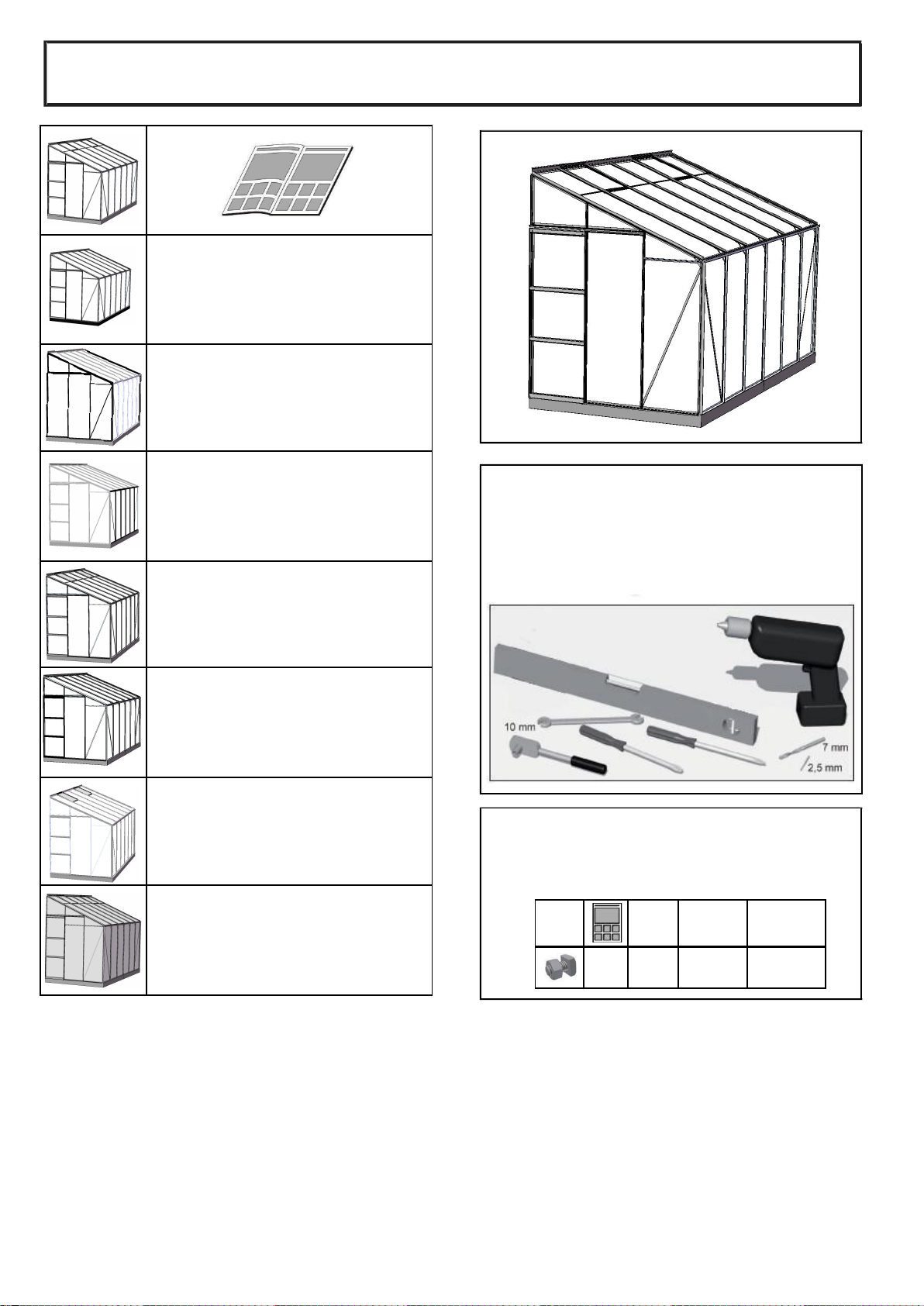
1. Thank you for selecting our greenhous
. Please read the instructions carefully bef
he metal edges aresharp.
3. Thi
only and we cannot accept li
4. At least 2 people are req
ontact us if you encounter pro
installation.
6. Do not force the components toge
ndy weather.
9. Make sure your greenhouse is co
ered by your household insurance
dversely affected by many che
cals including acids, ammonia,cement,iodine
leum.
11. Use warm soapy water and mil
nhouse.
IMPORTANTINFORMATIO
nts are present before you st
rt work.
2. The main components
rt number.
3. The parts list include
how the shape of each profil
NTH ASSEMBLY –see Page1
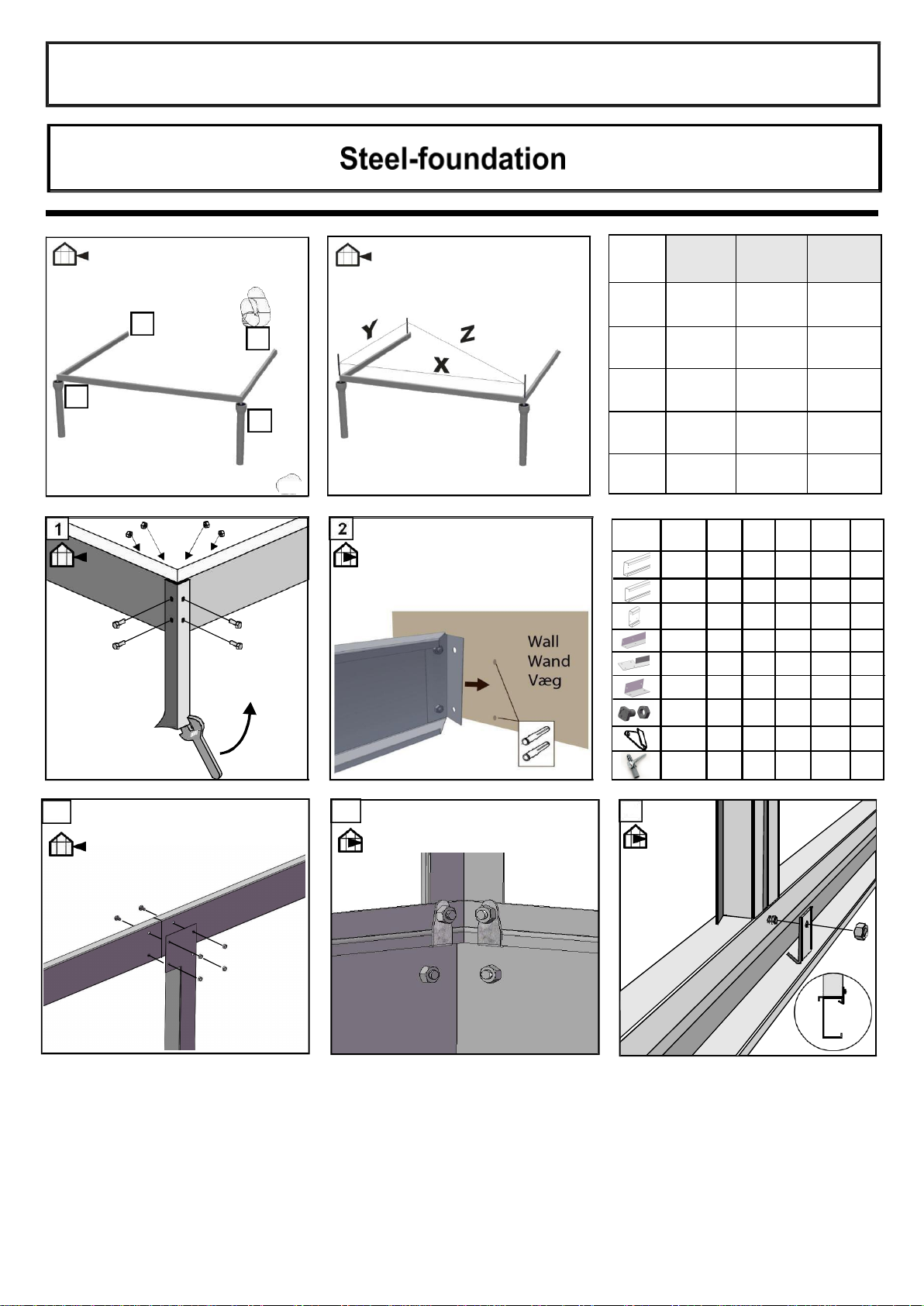
1. Page 1 of the instructions shows how to assemble the base pli
.
2. The base plinth must be level and squa
nd bolted to the glazing bars to ensure
linth.
5. It is important that eve
nstalled especially at a sit
which may be subject to stron
hat the base plinth is secu
ely anchored into the ground especi
corner pegs can be set in concrete or
o a patio or concrete using expanding bolts
r screws andplugs.
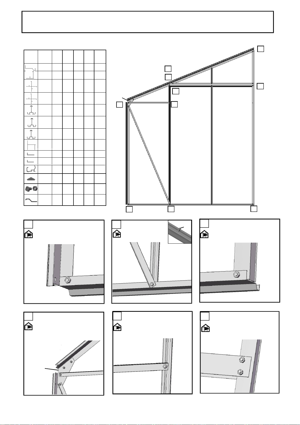
REAR WA
1. Page 2 of the instructions s
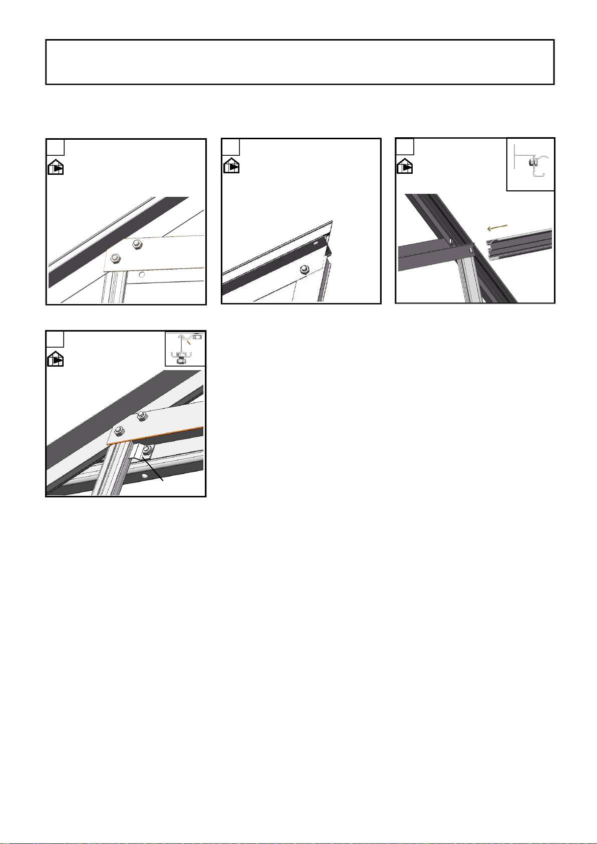
2.Before fixing the vertical glazi
a bolts into the bolt channels as requi
3
3