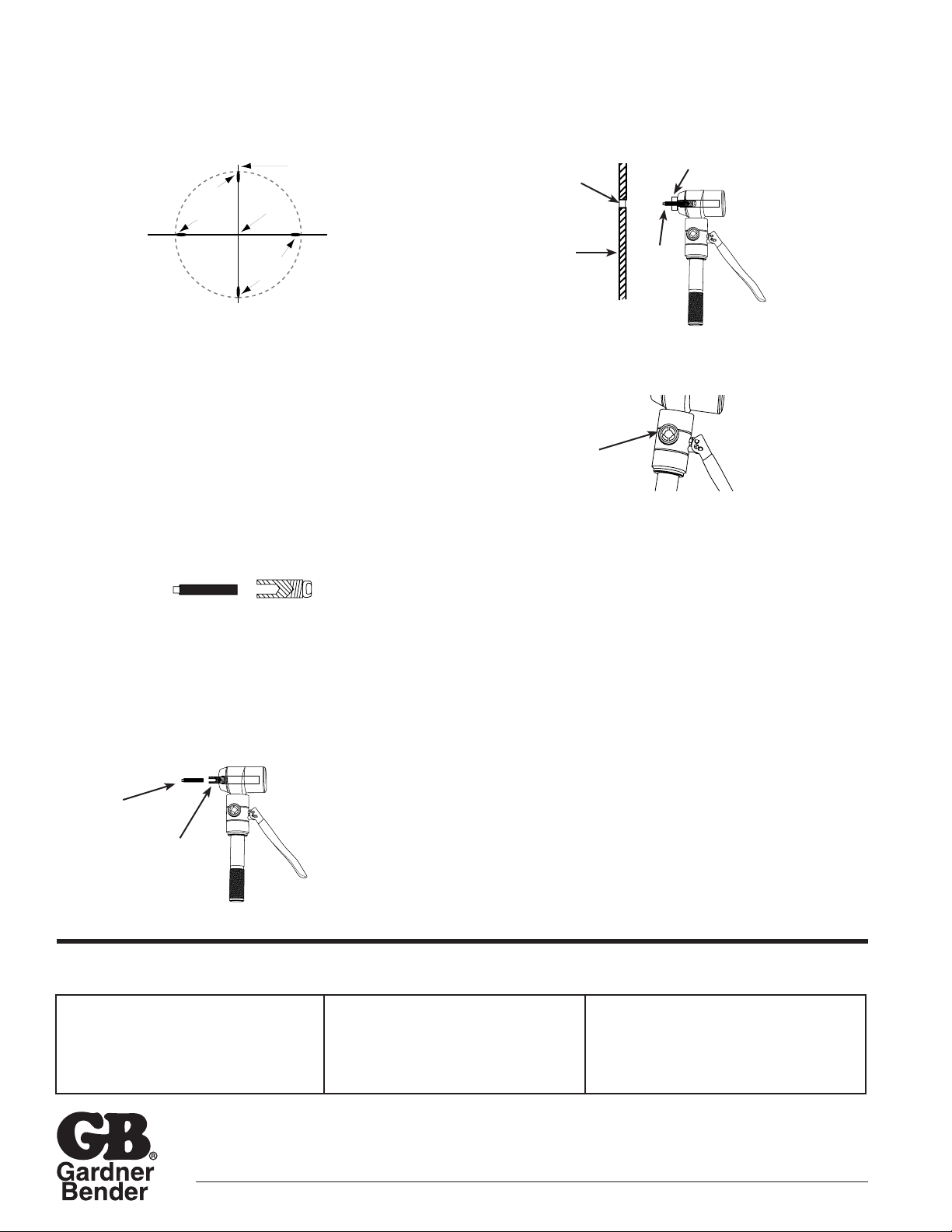
Drilling Guide Holes
1. Mark the center position, drill a 1/8" pilot hole. Enlarge
the hole with a 7/16" drill to provide pull rod clearance.
a. I f working to close tolerances, mark the center
position by scribing cross lines shown in Figure 1
b. When assembling the punch to the pull rod, align the
cross marks with the four marks on the outer die surface.
NOTE: If pre-punched knockouts are already in the
desired location, drilling a guide hole is not required.
2. For larger holes 3/4" to 2-1/2", the 1/2" punch is used to
make the guide hole.
Punching 1/2" Holes
1. Thread the pull stud into the pull stud adapter end until
firmly seated. (Figure 2)
NOTE: The pull stud and pull stud adapter are only used
with the 1/2" punch. The 1/2" punch is used to make
guide holes for larger punch sizes.
2. Attach the pull stud adapter to the cylinder by inserting
the pull stud adapter into the plunger opening and
threading until the pull stud extends beyond the end of
the cylinder. (Figure 3)
3. Slide the 1/2" die over the pull stud, flat side toward
the cylinder.
4. Insert the pull stud through the guide hole (Figure 4).
Attach the 1/2" punch to the pull stud. Turn the punch until
it is completely threaded onto the pull stud.
5. Close the pump release valve by turning it clockwise
(Figure 5). Hold the punch set in position, work the pump
handle until the punch completely penetrates the metal.
6. Remove the punch set from the hole. Turn pump release
valve counterclockwise to open. The cylinder will retract
and the slug must be removed from between the punch
and die.
Punching 3/4" through 2-1/2" Holes
1. Drill a pilot hole(7/16") install the 1/2" punch and make
guide hole. See Punching 1/2" Holes.
2. Remove the 1/2" punch and die set. Also remove the
pull stud and pull stud adapter.
3. Attach the pull rod (KPR7520) to the cylinder by inserting
the rod into the plunger opening and threading until the
pull rod extends beyond the end of the cylinder.
4. Select the punch set needed. Slide the die over the
pull rod.
5. Place the pull rod into the 1/2" guide hole, thread the
punch onto the pull rod. Be sure the pull rod extends
beyond the punch.
6. Operate the hand punch until the punch penetrates the
metal. Open the punch release valve. Remove the slug.
Note: To avoid excessive wear and tear on the pull rod threads during
punching, center the guide hole accurately enough so that the pull rod
does not rest against the metal edge of the guide hole. Also, be sure
that all points of the punch are in uniform contact with the metal surface
when starting to punch.
PARTS AND SERVICE: For quality workmanship and
genuine Gardner Bender parts, select an Authorized GB
Service Center for your repair needs. Only repairs
performed by an Authorized Service Center displaying the
official GB Authorized sign are backed with full factory
warranty. Contact Gardner Bender (414)352-4160 for the
name of the nearest GB Authorized Service Center.
REPAIR AND SERVICE INSTRUCTIONS: For repair service and parts contact your nearest Gardner Bender Service Center. The
Gardner Bender Service Center will provide complete and prompt service on all Gardner Bender products.
6100 N. Baker Road, Milwaukee, WI 53209 • Phone: (414) 352-4160 • FAX (414) 352-2377 TL_007 0110 ZX000249
Pump Release Valve Figure 5
Figure 4
Figure 3
Pull Stud
Adapter
Pull Stud
Pre-drill
7/16" Hole
Metal
Box
Dotted line
Indicates
Knock-Out
Die
Cross Lines
6" Long
Lines On
Die Line
Up With
Cross Lines
Center
Drilling of Guide Hole
Figure 1
Pull Stud
KPS50 Pull Stud
Adapter
KSA50
Figure 2
Draw
Stud
Die
WARRANTY: Gardner Bender warrants its product
against defects in workmanship and materials for 1 year
from date of delivery to user. Warranty does not cover
ordinary wear and tear, abuse, misuse, overloading,
altered products or use of improper fluid.
WARRANTY RETURN PROCEDURE: When
question of warranty claim arises, send the unit
to the nearest GB Authorized Service Center for
inspection, transportation prepaid. Furnish
evidence of purchase date. If the claim comes
under the terms of our warranty the Authorized
Service Center will REPAIR OR REPLACE
PARTS AFFECTED and return the unit prepaid.