Gardner Denver EMCO WHEATON E2110 Instruction manual

9111 Jackrabbit Road,
Houston, Texas 77095
Tel: 281-856-1 00
Fax: 281-856-1 25
www.emcowheaton.com
Rev.: 1
INSTALLATION, OPERATION &
MAINTENANCE MANUAL
The content of this paper is the intellectual property of EMCO WHEATON U A. Reproduc-
tion - also of extracts - is not permitted. Likewise, they must not in any way be made acces-
sible to third parties, in particular competitors.
This manual contains information that may not pertain to your arm.
EMCO WHEATON
Top & Bottom
Loading Arms

Instruction Manual
Top & Bottom Loading Arms
E2110, E2112, E2022, E2025
E20 , E2 04, E257 , E212 ,
E2 1 , E2121
Rev.: 1
Table of Contents
1 Safety.......................................................................................................................1
1.1 afety Comments.............................................................................................1
1.2 afety ymbols and Notes ...............................................................................2
2 Loading Arm Types ................................................................................................2
Loading Arm Description.......................................................................................
3.1 Loading Arm.....................................................................................................
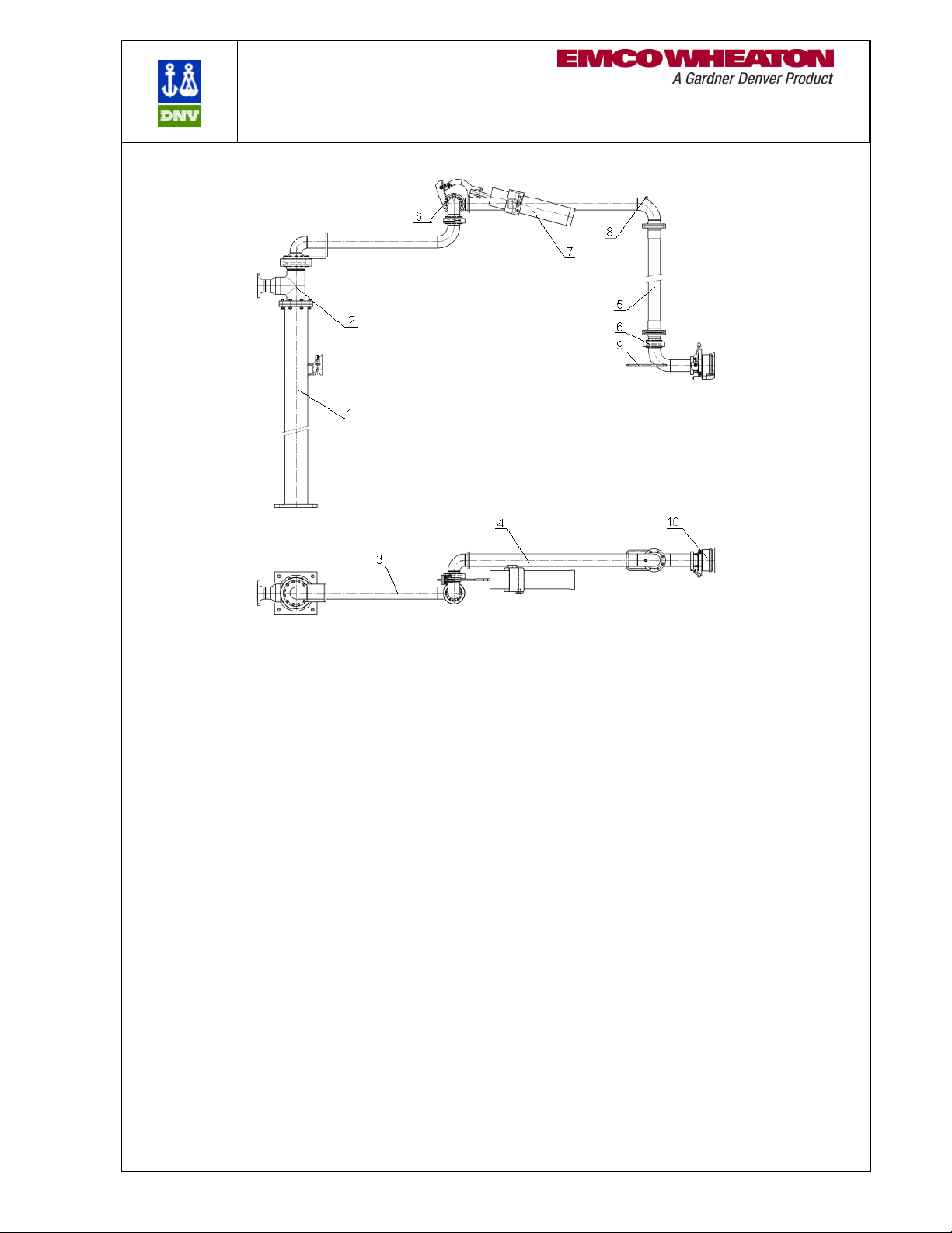
3.2 Main Components - Top Loading .....................................................................
3.3 urvey Drawing ................................................................................................4
3.4 Main Components - Bottom Loading ................................................................5
3.5 urvey Drawing ................................................................................................5
4 Warranty ..................................................................................................................6
5 Delivery and Storage ..............................................................................................6
6 Installation...............................................................................................................7
6.1 Installation of the Loading Arm .........................................................................7
6.2 Installation of Feed Lines .................................................................................9
7 Commissioning.......................................................................................................9
8 Operation of the Loading Arm.............................................................................10
8.1 Operation of Loading Arms with Open B-Length............................................10
8.2 Operation of the Loading Arms with Flange/Coupler......................................11
9 Service and Maintenance.....................................................................................11
9.1 afety Comments...........................................................................................11
9.2 pare Parts ....................................................................................................12
9.3 Regular Tests.................................................................................................12
9.4 General Maintenance .....................................................................................12
9.5 ervice Intervals.............................................................................................1
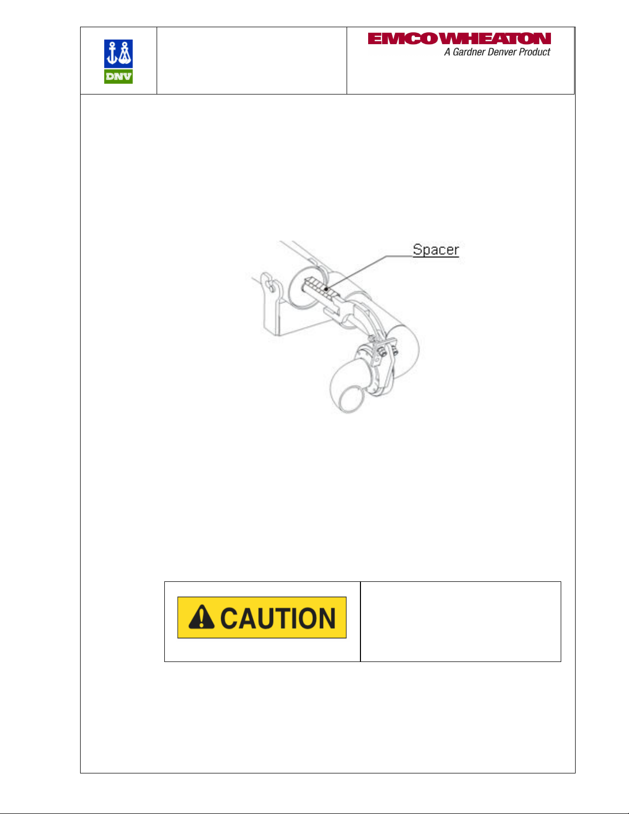
9.6 Lubrication Points at the Loading Arm............................................................1
9.7 Maintenance of wivel Joints .........................................................................14
9.7.1 Maintenance of D2000 wivel Joints.......................................................15
9.8 pring Cylinder Maintenance .........................................................................15
9.9 pring Cylinder Adjustment………………………………………………..…….. 16
9.10 Replacement and Disposal of pring Cylinder .............................................16
9.11 Bolt Connections ..........................................................................................16
9.12 Painting ........................................................................................................16
9.13 Hose.............................................................................................................16
9.14 Couplers.......................................................................................................17
9.15 Electrical Equipment.....................................................................................17
9.16 E0471 Loading Valve….............. ……………………………………………….17
9.17 Other Valve types……… ………………………………………………………...19

Instruction Manual
Top & Bottom Loading Arms
E2110, E2112, E2022, E2025
E20 , E2 04, E257 , E212 ,
E2 1 , E2121
- 1 -
1 Safety
1.1 Safety Comments
The following instruction manual describes the loading arm delivered by EMCO
WHEATON. It does not describe the loading system and does not include fittings
and devices which are not part of the loading arm.
This manual explains how to install, operate and maintain the loading arm,
helping to ensure safety and functionality.
Follow the instructions of this manual in all details. It does not release you from
the responsibility to perform the described steps in a professional and appropriate
manner.
Please refer to all drawings and additional documentation accompanying this
manual for important data pertaining to the loading arm.
The loading arm is intended to be assembled in a loading system. It must not be
used prior to the loading system being confirmed to correspond to the current
version of all local laws, regulations and requirements which apply. This manual
does not replace these rules in any way.
EMCO WHEATON offers on-site training for installation and maintenance of
supplied equipment.
Intended Use
EMCO WHEATON Loading Arms are movable pipes and joints for transferring
fluid between a fixed connection and a movable tank. Refer to the loading arm
general arrangement drawings for information about the conditions for using the
loading arm.
Any other use of the loading arm is not intended and therefore not permitted.
Do not change the structure of the loading arm in any way. Any changes may
endanger persons and/or cause the loading arm to become unsafe. Contact
EMCO WHEATON for information.
Do not use the loading arm when you notice it has been damaged or is
malfunctioning. Contact your supervisor immediately.
Only change the operating conditions of the loading arm with written permission by
EMCO WHEATON. The loading arm has been designed for the conditions described
in the drawings accompanying this documentation. Contact EMCO WHEATON for
authorization if the loading arm is required to exceed the conditions specified, to
ensure that the loading arm meets the new requirements.
Follow the instructions and warnings on the loading arm.
Do not cover or remove any signs on the loading arm.
The customer shall only allow staff working with the loading arm that:
are capable of safely handling the loading arm;
have been trained on proper handling the loading arm;
Understand the dangers of the loading arm.

Instruction Manual
Top & Bottom Loading Arms
E2110, E2112, E2022, E2025
E20 , E2 04, E257 , E212 ,
E2 1 , E2121
- 2 -
1.2 Safety Symbols and Notes
This instruction manual also indicates potential dangers of handling, operating and
maintaining loading arm. These dangers are highlighted in the text with an explanation
of how to avoid them. Observe the highlighted cautionary notes and be especially
careful in these situations. Explain these dangers to all persons working with or near
the loading arm.
Danger
This symbol indicates a hazardous
situation which will result in serious injury
or death, if not avoided.
Attention
This symbol indicates a hazardous
situation which could result in serious
injury or death, if not avoided.
Caution
This symbol indicates a hazardous
situation which may result in minor or
moderate injury, if not avoided.
Note
This symbol indicates additional
information and imposes no hazardous
situation.
2 Loading Arm Types
Refer to the drawings, parts lists and accompanying documentation for additional
information specific to your loading arm.
Attention
Operating the loading arm outside of
the specified conditions may damage
the loading arm which could result in
serious injury or death.
The loading arm has been designed
for the operating conditions shown on
the general arrangement drawings.
Please refer to the drawings and
ensure the arm is operated within the
specified limits.

Instruction Manual
Top & Bottom Loading Arms
E2110, E2112, E2022, E2025
E20 , E2 04, E257 , E212 ,
E2 1 , E2121
- 3 -
Loading Arm Description
.1 Loading Arm
The EMCO WHEATON Loading Arms are a movable pipe system for loading or
unloading railroad cars, tank trucks and other vessels. The transfer of fluid is
achieved by either introducing the loading arm into the manhole or making a
connection to the flange of the vessel. Please refer to the general arrangement
drawing for connection details.
EMCO WHEATON wivel Joints and counterbalance mechanisms provide
smooth and balanced movement of the loading arm in all directions. EMCO
WHEATON loading arms are also designed to be self-supporting.
.2 Main Components - Top Loading
Refer to Figure 1 and 2 in ection 3.3
1.
The F-Length provides reach in the horizontal plane. (boom style arms
only)
2.
The A-Length provides reach in the horizontal and vertical planes.
3.
The B-Length is introduced into or connected to the tank or vessel.
4.
Swivel joints connect piping and elbows allowing the loading arm to
articulate while maintaining a pressure tight seal.
5.
The spring cylinder balances the A-length and provides assisted
movement of the loading arm.
6.
The vacuum breaker introduces air into the arm and facilitates draining
of the loading arm.
7.
Handles are supplied to aid in manipulation of the loading arm.
8.
The loading valve is used to start and stop the product flow. EMCO
WHEATON loading valves feature an adjustable slow closing mechanism
to control the rate of closure to prevent line shock.
9.
Other valve types are used to start and stop the product flow of loading
arms for chemical, hot & food products.
10.
A remote control is used to assist in operating the loading valve while
the operator is visually monitoring the fluid level.
11.
The flange or coupler is used to connect the loading arm to the
corresponding connector on the vessel.
12.
A proximity switch (limit switch) can be installed to monitor the position
of the loading arm or the state of the product valve (open/closed).

Instruction Manual
Top & Bottom Loading Arms
E2110, E2112, E2022, E2025
E20 , E2 04, E257 , E212 ,
E2 1 , E2121
- 4 -
. Survey Drawing (
Model E2025 shown)
Figure 1
Figure 2

Instruction Manual
Top & Bottom Loading Arms
E2110, E2112, E2022, E2025
E20 , E2 04, E257 , E212 ,
E2 1 , E2121
- 5 -
.4 Main Components – Bottom Loading
Refer to Figures 3 and 4 in ection 3.5
1.
The stand post carries the loading arm. If several loading arms are
standing in a row, the stand post of each loading arm has a different height
to enable you to cross the hoses without collision.
2.
The intermediate tube carries the parking device.
3.
The F-Length provides reach in the horizontal range.
4.
The A-Length provides reach in the horizontal and vertical range.
5.
The B-Length is connected to the tank or vessel.
6.
Swivel joints connect piping and elbows allowing the loading arm to
articulate while maintaining a pressure tight seal.
7.
The spring cylinder balances the A-length and provides assisted
movement of the loading arm.
8.
The vent connection is used to vent the loader while filling it with product
or to accelerate draining for maintenance.
9.
Use the handle to move the loading arm.
10.
The coupler of the loading arm connects to the adapter at the tank or
vessel.
.5 Survey Drawing
(Model E2304 shown)
Figure

Instruction Manual
Top & Bottom Loading Arms
E2110, E2112, E2022, E2025
E20 , E2 04, E257 , E212 ,
E2 1 , E2121
- 6 -
Figure 4
4 Warranty
EMCO WHEATON grants a warranty for the loading arm. Refer to your order
confirmation or the EMCO WHEATON Terms and Conditions.
Items NOT covered under warranty are:
Damage caused by inappropriate handling and storage
Damage caused by faulty installation
Damage caused by incorrect adjustment
Components with removed or illegible labelling
Damage caused by incorrect operation
Worn parts
5 Delivery and Storage
All EMCO WHEATON products are secured and packed carefully at the factory.
Although the utmost care has been taken in preparing the loading arm for
shipment, please inspect for transport damages and completeness on receipt of
goods. Notify EMCO WHEATON about any findings or concerns immediately.
Claims submitted on a later date cannot be accepted.
tore the goods in a sheltered area as soon as the delivery is received and cover
them properly to protect them from dirt and moisture. Provide ventilation to avoid
corrosion caused by condensation.

Instruction Manual
Top & Bottom Loading Arms
E2110, E2112, E2022, E2025
E20 , E2 04, E257 , E212 ,
E2 1 , E2121
- 7 -
For loading arms not supplied with a finish coating, the customer is responsible
for painting the arm to provide corrosion protection.
Protect all hoses and cables against rodents. If the arm is to be stored for an
extended period, protect with a suitable preservative. Please contact EMCO
WHEATON for more information.
6 Installation
6.1 Installation of the Loading Arm
(E2025 & E2304 shown)
Attach suitable hoisting gear to the loading arm for lifting the loading arm and to
avoid damaging the loading arm.
Danger
During installation of the loading
arm it could turn or fall down
Keep a safe distance from the
loading arm while hoisting
Loosen the transportation locks and remove all packing material. Lift the loading
arm and remove the supporting frames. Mount the stand post or the wall bracket,
if supplied.
Pay close attention to a proper vertical alignment. Lift the loading arm until
mounting brackets align properly. The installation position of the loading arm is
horizontal (see drawing for correct inlet position). Bolt the swivel joint bracket to

Instruction Manual
Top & Bottom Loading Arms
E2110, E2112, E2022, E2025
E20 , E2 04, E257 , E212 ,
E2 1 , E2121
- 8 -
the support bearing bracket. Ensure that the slew axis of the boom is in a vertical
position. (previous note only applies when bracket or stand post is supplied)
The inlet flange attachment bolts and nuts are not included in the scope of
delivery. elect adequate bolts and nuts which are suitable for the weight and the
bending moment. Use all attachment provisions.
Connect the flanges and install gaskets at the flanges.
Remove the transport locks from the loading arm and spring cylinder ( ee Figure
5 below).
Figure 5
Install components supplied separately (such as overfill device, parallel guide,
hoses, couplers etc., if applicable). Refer to the loading arm drawing for more
information.
Once installed, move the loading arm and verify that it will hold its position. If the
loading arm slews about its axis, ensure that the mounting flange is level. If the
arm is not properly balanced, adjust the balance of the spring cylinder (refer to
the spring cylinder adjustment manual for procedure). Although all components
have been adjusted to proper values by the factory, minor adjustments may be
required.
Caution
If the loading arm is inadequately
balanced or moves on its own it may hit
persons nearby causing injury.
Adjust arm and mounting flange to suit.
Ensure not to enclose any objects in the system (e. g. tools or bolts). Clean all
tubes before final installation.
The operator of the system is responsible for grounding the system and
protecting it from lightning.
Only persons with the required training and qualification should connect and
maintain the electrical, pneumatic or hydraulic systems. Connect these systems
according to the accompanying diagrams and data sheets.

Instruction Manual
Top & Bottom Loading Arms
E2110, E2112, E2022, E2025
E20 , E2 04, E257 , E212 ,
E2 1 , E2121
- 9 -
Note
All control components have been adjusted to correct
values during fabrication. Do not change these values
without written consent from EMCO WHEATON.
6.2 Installation of Feed Lines
Only persons with the required training and qualification (i.e. electricians for the
electrical systems or mechanics for the pneumatic and hydraulic system) are al-
lowed to work on the electrical, pneumatic and hydraulic system.
Install and connect all pneumatic and hydraulic lines according to appropriate
industry standards. Fittings, dimensions and quality of the components must be
selected to meet the requirements of the installation.
Clean all pipes and containers from dirt (scales, sand, swarf etc.) before installa-
tion.
Connect the electrical system, the pneumatic system and the hydraulic system (if
applicable) according to the diagrams and data sheets in the appendix.
All components have been adjusted to their values during fabrication. Do not
change these values without our written consent.
Only use dry and clean air or nitrogen for the pneumatic system.
7 Commissioning
Do not operate the loading arm when you notice any damage. Please contact
EMCO WHEATON.
Purge the system (loading arm and pipes) before using for the first time to avoid
damaging the swivel joints and fittings.
Perform the following tests:
Leakage Test
Leak test by means of air or nitrogen of 7 to 15 psi and a foam-forming
substance.
Operating Range/Balancing
Check the operating range once again by moving the A/B/F-lengths of the
loading arm into the extreme positions. Verify with the help of the general
arrangement drawing.
Functional Test:
Operate the loading arm as described in ection 8. Test the function of all
instruments, accessories and signals.
Do not exceed the allowable operating pressure and operating temperature.

Instruction Manual
Top & Bottom Loading Arms
E2110, E2112, E2022, E2025
E20 , E2 04, E257 , E212 ,
E2 1 , E2121
- 10 -
8 Operation of the Loading Arm
Refer to the loading arm general arrangement drawing and/or envelope drawing
for information about the operating data of the loading arm.
Warning
Explosion hazard – sparks due to static
electricity.
You may be severely injured or killed, if
sparks ignite product vapours in the air.
Ground the tanker before beginning the
loading process.
Check the loading arm operating conditions before beginning the loading process and
whether the required conditions are met. top the loading immediately when you
notice malfunction and/or damage and inform a supervisor immediately.
The loading process is defined by the customer.
Note
EMCO WHEATON recommends purging
the loading system (loading arm and
pipes) before loading to avoid damaging
the swivel joints and fittings.
Warning
Explosion hazard – metal parts can hit
and cause sparks.
You may be severely injured or killed, if
sparks ignite product vapours in the air.
Move the loading arm slowly and do not
release while still in motion.
8.1 Operation of Loading Arms with Open B-Length
Remove the loading arm from its parking position and move to the tanker. Introduce
the B-Length into the manhole. The loading arm is now ready for loading. The
loading process is defined by the customer. When all requirements for the loading
process are fulfilled, open the loading valve or the ball valve to start loading (if
applicable).
Caution
Only use your hands to operate the
loading valve or remote control. Do not
block or fix the remote control in any way
(e.g. tie it with a rope).
When the loading process has finished, release the remote control to close the
loading valve or turn handle on ball valve. Let the arm drain and raise the B-

Instruction Manual
Top & Bottom Loading Arms
E2110, E2112, E2022, E2025
E20 , E2 04, E257 , E212 ,
E2 1 , E2121
- 11 -
Length from the manhole. Return the loading arm to its parking position and
secure.
Note
Product remaining in the pipe might damage the swivel joints.
Drain the arms completely before returning to parking position.
8.2 Operation of the Loading Arms with Flange/Coupler
This section describes how to operate the loading arms with Dry-Break couplers
or flange connections on drop tube.
Remove the loading arm from its parking position and move to the tanker.
Connect the B-Length to the connection point at the tank. Make the appropriate
connection for end fitting.
The loading arm is now ready for loading. The loading process is defined by the
customer.
When the loading process has finished, close appropriate valve. Let arm drain if
required and disconnect the B-Length from the tank. Return the loading arm to its
parking position and secure.
9 Service and Maintenance
9.1 Safety Comments
A. EMCO WHEATON recommends using EMCO WHEATON ervice to maintain
the equipment.
B. Only persons who are able to perform all tasks professionally due to their train-
ing and qualification are allowed to repair the loading arm (e. g. electricians for
the electrical system). Contact EMCO WHEATON if the loading arm is severely
damaged.
C. ecure the loading arm while performing maintenance tasks to avoid it from
moving unexpectedly.
D. Take special care and use adequate hoisting devices (cranes, belts) when lifting
heavy components when performing maintenance tasks.
Warning
evere injury or death could result if the
product leaves the loading arm under
high pressure or if you open hydraulic
lines.
Purge the loading arm and depressurize
lines when servicing any components of
the loading arm.

Instruction Manual
Top & Bottom Loading Arms
E2110, E2112, E2022, E2025
E20 , E2 04, E257 , E212 ,
E2 1 , E2121
- 12 -
9.2 Spare Parts
Only use original EMCO WHEATON spare parts. Please refer to the spare parts
listing for your recommended loading arm spares. Our spares & service department
will be happy to provide you with a quotation.
9. Regular Tests
Perform regular tests according to recommendations in the following sections as well
as any applicable local safety regulations/laws.
9.4 General Maintenance
Caution
Do not use a high-pressure cleaner to
clean the loading arm. Prevent any static
electricity when you are cleaning plastic
parts.
EMCO WHEATON recommends EMCO WHEATON ervice to service and main-
tain the loading arm. If you prefer having the loading arm maintained by your
staff, EMCO WHEATON offers training which explains the equipment of your
loading arm and can be performed on-site.
Refer to section 9.5 for information about maintenance intervals.
Note
If EMCO WHEATON ervice carries out maintenance, the
customer must provide a material safety data sheet of the
product loaded and additionally a risk assessment.

Instruction Manual
Top & Bottom Loading Arms
E2110, E2112, E2022, E2025
E20 , E2 04, E257 , E212 ,
E2 1 , E2121
- 13 -
9.5 Service Intervals
ervice Interval
Component
Each
Loading
Every 6
Months Annually As
Required
9.6 Open Lubrication Points •
9.7
Maintenance of wivel Joints O •
9.8
pring Cylinder Maintenance •
9.9
pring Cylinder Adjustment •
9.10
Replacement and Disposal of
pring Cylinder •
9.11
Bolt Connections X
9.12
Painting •
9.13
Electrical Equipment O •
9.14
Loading Valve O •
9.15 Other Valve Types O
9.16 Hose O •
9.17 Coupler O •
O = Check for proper operation. ervice the component only, if necessary.
•
••
• = ervice as described in the according section of this manual.
X = 6 months after commissioning or after 6 loadings, whichever comes earlier.
After 1
st
service check every other year only.
9.6 Open Lubrication Points
Please refer to the figure below for location of open lubrication points. Apply a
thin layer of lubricant every 6 months or as necessary depending on loading
environment.
Use the same lubricant which is listed in the loading arm drawing for open
lubrication points.

Instruction Manual
Top & Bottom Loading Arms
E2110, E2112, E2022, E2025
E20 , E2 04, E257 , E212 ,
E2 1 , E2121
- 14 -
9.7 Maintenance of Swivel Joints
EMCO WHEATON swivel joints are designed for minimum maintenance.
Maintenance often consists of a visual inspection. Clean the slot of the dust O-
ring annually with a suitable cleaning agent and soft bristled brush.
The lubricant is specifically chosen for the individual application (see general ar-
rangement drawing). EMCO WHEATON recommends opening the swivel joints
only when they are leaking or damaged.
Only use original EMCO WHEATON spare parts. Our spares & service
department will be happy to provide a quotation.
Only applies, if your loading arm is equipped with these accessories
.
Open lubrication
points without grease
nipple

Instruction Manual
Top & Bottom Loading Arms
E2110, E2112, E2022, E2025
E20 , E2 04, E257 , E212 ,
E2 1 , E2121
- 15 -
9.7.1 D2000 Swivel Joints
Each D2000 swivel joint is provided with a bolt (Item #6) in the ball race plug
(Item #5). To visually check the lubrication, remove bolt (item #6) only. Do not
remove the ball race plug (item #5) as balls may fall out.
The D2000 swivel joints are provided with grease sufficient for 5 years of service
provided that the seals are intact and pressure and temperature limits are not
exceeded. For heated or chemical applications the swivels are warranted for 1
year of service. In these applications the grease should be checked and re-
greased annually.
D2000 grease kits include a grease nipple and standard tube of grease specific
to the application. Use the grease nipple at the swivel joint casing to lubricate
the swivel joint. Rotate the swivel joint while greasing to distribute the lubricant.
9.8 Spring Cylinder Maintenance
The spring cylinder balances the A-length of the loading arm and enables smooth
movement within the operating range of motion. The loading arm is neutrally
balanced at the factory to maintain its position when at rest.
Grease the pivot joints and the cylinder rod every six months. Check the spring
cylinder for damage.
Make sure that the warning placard is attached to the spring cylinder. Replace it
immediately when damaged or missing.
Warning
The spring cylinder contains stored
energy. When adjusting use extreme
care or severe injury could result
Only authorized persons shall maintain
the spring cylinder who have been
trained by EMCO WHEATON

Instruction Manual
Top & Bottom Loading Arms
E2110, E2112, E2022, E2025
E20 , E2 04, E257 , E212 ,
E2 1 , E2121
- 16 -
9.9 Spring Cylinder Adjustment
ee detailed instruction manual.
9.10 Replacement and Disposal of Spring Cylinder
Contact EMCO WHEATON in this matter.
9.11 Bolt Connections
Check all bolts for tightness and tighten to correct torque values after the first six
months of operation or after the 6
th
loading process (which ever comes first). Repeat
this check every other year.
Bolt Torque [Nm] at µ=0,14
(Standard Friction)
Strength Class
Dimensions 6.8 8.8 B7 10.9 12.9 A4-70
M8 19 25 35 41 17.8
M10 37 49 72 84 36
M12 65 85 125 145 62
M16 150 200 230 290 340 150
M18 200 270 320 400 470 210
M20 290 390 450 570 670 303
M22 400 530 610 780 920
M24 500 670 770 980 1150 290
M27 740 990 1140 1450 1700 410
M 0 1000 1340 1550 1970 2300 556
M 1370 1820 2100 2680 3130
M 6 1760 2340 2700 3430 4020
M 9 2280 3040 3520 4460 5220
M42 2820 3760 4350 5530 6470
9.12 Painting
If the loading arm has not been painted (refer to your order confirmation) the
customer must paint the loading arm to provide corrosion protection. Use the
same paint to repair any damage in the painting to ensure long-term corrosion
protection.
9.1 Hose
Check the hoses regularly for damage and leakage.

Instruction Manual
Top & Bottom Loading Arms
E2110, E2112, E2022, E2025
E20 , E2 04, E257 , E212 ,
E2 1 , E2121
- 17 -
9.14 Couplers
Check the couplers for damage and leakage regularly. Maintain coupler
according to the instructions of the manufacturer. All Emco Wheaton API
couplers include a detailed instruction manual.
9.15 Electrical Equipment
Check the electrical equipment regularly. Replace loose connections and burned
or damaged cables immediately.
Electric Shock
Disconnect the power from electrical
systems before performing inspections,
maintenance or repairs.
9.16 E471Loading Valve
EMCO WHEATON Loading Valves are maintenance-friendly.
The loading valve can be located on all lengths of the loading arm.
Check loading valve for leaks with each loading cycle and replace seals as
necessary. Refer to the Figure on page 16 for section views and parts list.
Instructions for Opening the Valve the First time:
1. Move the arm in the loading position. The A-length should be near or below
horizontal.
2. Open the product valve slightly to provide roughly 1/16 of the normal flow rate.
3. Once valve is free from air, open fully and allow to close. Repeat as necessary
to remove any remaining air trapped in the valve.
The valve is free of air upstream when the valve closes smoothly with a small
delay as soon as you release the lever.
Use the product valve for normal operation.
Adjustment of Closing Speed:
You can adjust the loading valve depending on the flow rate and the viscosity of
the product to close within the shortest time without a pressure line shock.
The closing time of the loading valve is set during assembly to a value which lets
about 50 to 60 L pass at a product flow of 2000 L/min until the valve is completely
closed.
To adjust the closing speed, remove pipe plug (Item #2), and using a blade
screwdriver turn the adjusting screw (Item #5). Check the closing time after each
medium turn of the adjusting screw until the desired closing-time is found.
Turn the adjusting screw clockwise to increase the closing time.
Turn the adjusting screw counter-clockwise to reduce the closing time.

Instruction Manual
Top & Bottom Loading Arms
E2110, E2112, E2022, E2025
E20 , E2 04, E257 , E212 ,
E2 1 , E2121
- 18 -
ITEM DE CRIPTION MATERIAL QTY. PART No.
1 Bonnet Alum. 1 454311
2 Pipe plug 1/8” npt teel 1 404936
3 Bonnet gasket Fiber 1 444938
4 Body FNPT ends Alum. 1 454314
5 Adjusting screw teel 1 454312
6 pring teel 1 443956
7 Pilot valve guide t 1 443984
8 Cotter pin t 1 405034
9 Pilot valve Alum. 1 445069
10 Plunger Alum. 1 446995
11 Plunger disc Buna 1 446522
11 Plunger disc Viton 1 446523
12 Pipe plug 3/8” npt teel 1 447574
13 Roll pin t 1 564800
14 Cam Alum./Brnz 1 440570
15 Plunger guide stem t 1 443986
16 Plunger guide Alum. 1 452744
17 Cotter pin t 1 405034
18 HH screw 5/16/18 t 4 565470
19 Plunger ring PTFE 1 446001
20 Lock washer 5/16 teel plt’d 9 470034
21 Bonnet screw 5/16 teel plt’d 8 452345
22 Warning tag Paper 1 564804
23 Operating handle Cast iron 1 443220
24 Flat washer Brass 1 402912
25 HH screw ¼-20 teel plt’d 1 403112
26 HH screw 5/16-18 teel plt’d 1 444519
27 Hex nut 5/16-18 teel plt’d 1 403150
28 Gasket Fiber 1 443409
29 Packing nut Brass 1 443972
30 O-ring Buna 2 443451
30 O-Ring Viton 2 566295
31 Bushing Brass 1 444746
32 Cam operating stem t 1 450898
This manual suits for next models
9
Table of contents
Other Gardner Denver Industrial Equipment manuals