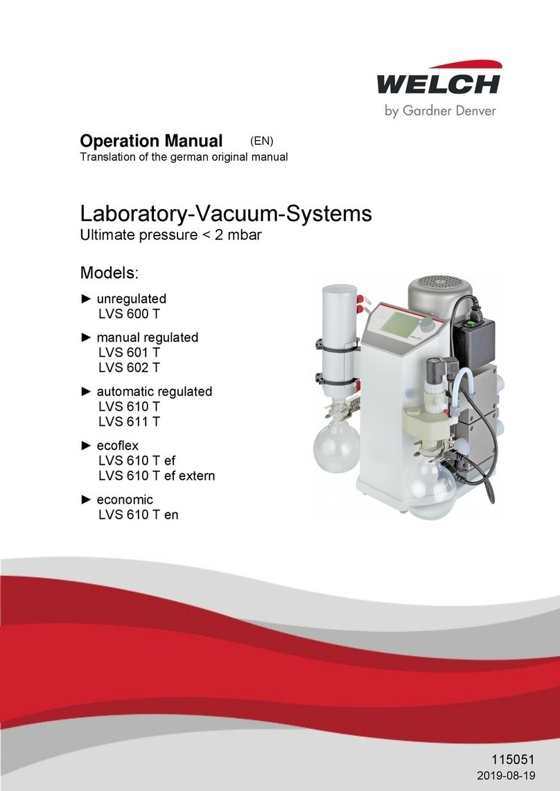
Gardner Denver Welch LVS 105 T 10 ef+ User manual

Operation Manual
(EN)
Translation of the original operation manual
Laboratory vacuum system LVS
Types:
► LVS 105 T – 10 ef+
124184
Revision: 02020-04-09
600100
Revision: 02020-04-09

Manufacturer
Gardner Denver Thomas GmbH
Am Vogelherd 20
98693 Ilmenau
Germany
Imprint
© 2020
Reprint or duplication, also in excerpt,
are not permitted without written ap-
proval from Gardner Denver Thomas
GmbH.
All rights under the copyright laws are
expressly reserved by Gardner Den-
ver Thomas GmbH.
We reserve the right to make changes
and amendments.
Tel.: +49 3677 604 0
Fax: +49 3677 604 131
E-mail: welch.em[email protected]
Web: www.gardnerdenver.com/de-de/welch

Contents
Operation Manual LVS 105 T –10 ef+3
Contents
1Important Information ..................................................................................6
1.1 Note for the user/personnel ......................................................................................................6
1.2 Depiction of warning notices and information...........................................................................7
1.3 Explanations of safety symbols.................................................................................................7
1.4 Legend for the abbreviations ....................................................................................................8
2Safety...........................................................................................................10
2.1 General ...................................................................................................................................10
2.1.1 Proper use.............................................................................................................................. 10
2.1.2 Improper use.......................................................................................................................... 10
2.1.3 Foreseeable misuse............................................................................................................... 11
2.2 Target groups..........................................................................................................................11
2.2.1 Personnel qualification........................................................................................................... 11
2.2.2 Overview of the responsibilities ............................................................................................. 11
2.3 Protective measures...............................................................................................................12
2.4 Special hazards ......................................................................................................................12
2.4.1 Hazardous materials in general............................................................................................. 13
2.4.2 Explosive gases..................................................................................................................... 14
2.4.3 Electricity................................................................................................................................ 14
2.4.4 Mechanics.............................................................................................................................. 14
2.4.5 Vacuum.................................................................................................................................. 15
2.5 Device-specific hazards..........................................................................................................15
2.5.1 Reliable operation.................................................................................................................. 15
2.5.2 Temperatures......................................................................................................................... 15
2.5.3 Operating fluid........................................................................................................................ 16
2.5.4 Vacuum controller –system functions................................................................................... 16
2.5.5 Network safety ....................................................................................................................... 17
3Technical data.............................................................................................18
3.1 Dimensions .............................................................................................................................18
3.2 Characteristic values...............................................................................................................19
3.3 Supply and control connections..............................................................................................20
3.4 Application connections ..........................................................................................................20
3.5 Parts in contact with internal gas............................................................................................21
4Description..................................................................................................22
4.1 Field of application..................................................................................................................22
4.2 Function ..................................................................................................................................22
4.3 Set-up......................................................................................................................................22
4.3.1 Front of the device ................................................................................................................. 22
4.3.2 Back of the device.................................................................................................................. 23
4.4 Connection diagram, rotary evaporator ..................................................................................24
4.5 Attachments............................................................................................................................25
4.6 Operating elements and navigation of the vacuum controller ................................................26

Contents
4 Operation Manual LVS 105 T –10 ef+
4.6.1 Operating elements and display.............................................................................................26
4.6.2 Navigation ..............................................................................................................................28
4.7 Interfaces................................................................................................................................ 28
4.8 Accessories (options)............................................................................................................. 29
5Set-up and connection .............................................................................. 30
5.1 Unpacking .............................................................................................................................. 30
5.2 Set-up..................................................................................................................................... 30
5.3 Connection............................................................................................................................. 30
5.4 Electrical connection .............................................................................................................. 31
5.5 Storage................................................................................................................................... 31
6Operation.................................................................................................... 32
6.1 Bringing into service............................................................................................................... 32
6.2 Operating modes and system settings................................................................................... 32
6.2.1 Operating mode 1 Manual......................................................................................................32
6.2.2 Operating mode 2 Automatic .................................................................................................33
6.2.3 Operating mode 3 Program....................................................................................................34
6.2.4 Operating mode 4 Multi-pump................................................................................................35
6.2.5 Operating mode 5 Self-cleaning.............................................................................................36
6.2.6 System settings......................................................................................................................37
6.3 Configuring the vacuum control ............................................................................................. 41
6.3.1 Access control........................................................................................................................41
6.3.2 Log files..................................................................................................................................41
6.3.3 Reset to factory settings.........................................................................................................42
6.4 "PC-Control 601" PC software (Option) ................................................................................. 42
6.4.1 Installation ..............................................................................................................................42
6.4.2 Connection settings................................................................................................................43
6.4.3 Main screen............................................................................................................................44
6.4.4 File..........................................................................................................................................45
6.4.5 Log files..................................................................................................................................46
6.4.6 Settings ..................................................................................................................................48
6.4.7 Calibrate.................................................................................................................................49
6.4.8 Firmware update ....................................................................................................................50
6.5 Solvents table......................................................................................................................... 51
7Elimination of operating faults.................................................................. 52
8Maintenance ............................................................................................... 54
8.1 Service and inspection........................................................................................................... 54
8.2 Repairs by the operator.......................................................................................................... 55
8.2.1 Opening the device ................................................................................................................55
8.2.2 Replacing the components in the pump unit..........................................................................56
8.2.3 Installing the pump unit ..........................................................................................................58
8.2.4 Closing the device..................................................................................................................59
8.3 Repairs by the manufacturer.................................................................................................. 59
8.4 Damage report ....................................................................................................................... 59

Contents
Operation Manual LVS 105 T –10 ef+5
8.5 Disposal ..................................................................................................................................59
9Spare parts overview..................................................................................60
9.1 Diaphragm pump service set..................................................................................................60
9.2 Ordering and service contact..................................................................................................60
10 Appendix .....................................................................................................61
10.1 EU declaration of conformity...................................................................................................61
10.2 Notes.......................................................................................................................................62

Important Information
6 Operation Manual LVS 105 T –10 ef+
1 Important Information
ATTENTION
►Read operation manual carefully before use.
►Keep operation manual for later reference.
1.1 Note for the user/personnel
Safety
The user/personnel must have read and understood the operation manual completely be-
fore starting work.
The operation manual must always be kept in the place it will be used and be available to
the user/personnel.
The product may not be transferred without the operation manual.
Safe operation can only be guaranteed with proper and correct use of the product. The
safety instructions must be heeded!
General
Vacuum apparatus/vacuum system generally refers a combination of components for
vacuum applications, such as rotary evaporator with a vacuum control device and vac-
uum pump.
The operator is responsible for the proper use of vacuum apparatuses/vacuum systems.
About this device
For here on in, the laboratory vacuum system (LVS for short) will be referred to as "de-
vice".
"Device" describes the entire system consisting of the integrated vacuum pump, vacuum
controller, attachments and various other parts.
In general, the pneumatic input (the connection to the application) is referred to as the "in-
take side" and the output (the connection to the exhaust) is called the "pressure side".
The integrated "VCpro" vacuum controller is a system for controlling the vacuum system
and will be referred to as the "vacuum controller" below.
oVCpro 601: Vacuum pressure control via an electromagnetic vacuum control valve
oVCpro 602: Vacuum pressure control via a speed-controlled vacuum pump

Important Information
Operation Manual LVS 105 T –10 ef+7
1.2 Depiction of warning notices and information
The warning notices are depicted as follows:
Additional
symbols
DEGREE OF RISK
►Warning about possible hazards.
►Consequences if warning is not heeded.
►Heed note to prevent!
Degree of risk
DANGER
►Indicates a threatening risk that results in
dangerous injuries or death.
WARNING
►Indicates a possibly hazardous situation
which, if not avoided, can result in serious in-
juries or life-threatening consequences.
CAUTION
►Indicates a possibly hazardous situation. If
not avoided, this can result in light injury.
Depiction of information
Addi-
tional
symbol
SIGNAL WORD
►Important information for the user/operator.
1.3 Explanations of safety symbols
Symbol
Explanation
►General warning symbol
►High voltage warning
►Explosive materials warning
►Hot surface warning
►Poisonous substances warning
►Warning against low temperatures

Important Information
8 Operation Manual LVS 105 T –10 ef+
Symbol
Explanation
►General prohibition
►General mandatory sign
►Disconnect from power
►Protective clothing –gloves
►Protective clothing –goggles
►Heed operating instructions
►Components endangered by electrostatic discharge (ESD)
►General information
1.4 Legend for the abbreviations
Abbrevia-
tion
Designation or meaning
Explanation
A
Ampere - current strength
Electrical unit
abs
absolute
Value specification
AC
Alternating current
Electrical unit
ATM
Atmosphere
Pressure specification
DC
Direct current
Electrical unit
DN
Nominal diameter –inner diameter
(French: diamètre nominal)
Dimension specification
EPDM
Ethylene propylene diene rubber
Material
EX
Exhaust
Connection designation
FFKM
Perfluorinated rubber
Material
FKM
Fluorinated rubber
Material
FS
Full scale
Scale end value
FSS
Level sensor (German: Füllstandssensor)
Component
hh:mm:ss
hour / minute / second
Time specification

Important Information
Operation Manual LVS 105 T –10 ef+9
Abbrevia-
tion
Designation or meaning
Explanation
hPa
Hektopascal (1 hPa = 1 mbar = 0.75 Torr)
Pressure unit
Hz
Hertz - frequency
Electrical unit
IN
Intake
Connection designation
LVS
Labor-vacuum-system
Device model
max.
Maximum
Value specification
mbar
Millibar (1 mbar = 1 hPa = 0.75 Torr)
Pressure unit
min.
Minimum
Value specification
mm
Millimeter
Dimension specification
MPC
Diaphragm pump, chemically resistant
(German: Membran Pumpe)
Device model
pneum.
pneumatic
Connection designation
PP
Polypropylene
Material
PTFE
Polytetrafluorethylene
Material
PVDF
Polyvinylidene fluoride
Material
r.F.
Relative humidity in %
(German: relative Feuchte)
Environmental condition
Torr
Torr (1 Torr = 1.33 mbar = 1.33 hPa)
Pressure unit
V
Volt - voltage
Electrical unit
VCpro 601
Vacuum controller - vacuum control valve
Device variant
VCpro 602
Vacuum controller - motor speed control
Device variant
W
Watt –power
Electrical unit
WV
Water valve
Component

Safety
10 Operation Manual LVS 105 T –10 ef+
2 Safety
2.1 General
Anyone who plans to use the device must have read and understood the following safety
and warning notices.
Activities may only be performed by trained personnel who are familiar with the special
hazards and heed them and who have understood how the device functions and the op-
eration manual.
The device may only be used if it is in technically perfect condition.
2.1.1 Proper use
The device is intended for indoor use. The environment must be non-explosive.
Operation of the device is only permissible under the conditions named
in section 3 Technical data,
on the type plate,
and in the technical specification for the order in question.
Furthermore, proper use includes:
Heeding the operation manual
Heeding the warning/safety measures in this operation manual and of the connected de-
vices
Adherence to the operation manuals for connected vacuum pumps and vacuum control
devices from Gardner Denver Thomas GmbH
Use of approved spare parts and accessories from Gardner Denver Thomas GmbH
►Any other use will be regarded as improper!
2.1.2 Improper use
CAUTION
►With proper use, personal injury or property damage can occur.
►The operator must ensure proper operation!
The following is regarded as improper use:
Use that does not correspond to the proper use
Use outside of the specifications of the technical data, the type plate or the conditions
named in the delivery contract
Operation in less-than-perfect technical condition
Operation with missing or defective protective equipment
Operation outdoors
ATTENTION
►Uses that are improper must be prevented by the operator or measures
must be taken that ensure proper operation!

Safety
Operation Manual LVS 105 T –10 ef+11
2.1.3 Foreseeable misuse
ATTENTION
►Misuse is generally FORBIDDEN. It also counts as improper!
Regarded as foreseeable misuse are the following:
Operation in explosive environments (see section 2.4.2 Explosive gases)
Conveying of critical media (outside of the specifications in section
6.5 Solvents table)
Manipulation of the software and hardware, such as impermissible attachments and mod-
ifications
Leaving critical applications unsupervised
Operation of the device with tools or other impermissible objects
2.2 Target groups
ATTENTION
►There can be misuse due to use by untrained personnel.
►The operator must ensure that the personnel is trained properly and all
necessary safety measures are adhered to!
2.2.1 Personnel qualification
Target group
Area of activity
User
Laboratory personnel, e.g. chemists
Specialized personnel
Person with professional qualifications, e.g. mechanic, electri-
cian, laboratory director, etc.
Manufacturer
Service and maintenance/repair may only be performed by the
manufacturer or authorized service providers
2.2.2 Overview of the responsibilities
Activity
User
Special-
ized per-
sonnel
Manufacturer
Setup/connection
x
x
x
Bringing into service
x
x
x
Network integration
x
x
Operation
x
x
x
System settings
(1)
x
x
Sensor calibration
x
x
x
Factory settings
(1)
x
x
Troubleshooting
x
x
x
Firmware update
x
x
x
Analysis of operating fault
x
x
x
Elimination of operating fault
(2)
x
x
Maintenance/inspection, external
x
x
x
Maintenance/inspection, internal
(2)
x
x

Safety
12 Operation Manual LVS 105 T –10 ef+
Activity
User
Special-
ized per-
sonnel
Manufacturer
Self-cleaning
x
x
Repairs by operator
(2)
x
Damage report
x
x
Decontamination
(3)
Disposal
x
x
(1) Access can be blocked by the user (see section 6.3.1 Access control).
(2) Performed by specially trained users
(3) Performed by qualified and authorized service providers only
2.3 Protective measures
All protective measures must be the highest priority in order to protect the life and health of
personnel. In case of potential safety hazards, these must be assessed and measures taken
to avoid hazards. Uses that endanger health and life are not permitted.
Applicable operating instructions from the operator and the national regulations for accident
prevention, safety and occupational safety must be heeded.
PROTECTIVE CLOTHING
►For applications that require protective clothing, this clothing must be
worn for personal safety.
►The operator must specify the type and manner of protective clothing!
2.4 Special hazards
EMERGENCY OFF
►In dangerous situations, de-energize the device by pressing the power
switch or disconnecting the power plug.
DE-ENERGIZED STATE
►When the device is de-energized, all valves are closed and the motor
stops.

Safety
Operation Manual LVS 105 T –10 ef+13
2.4.1 Hazardous materials in general
WARNING
►Hazardous materials in the medium to be conveyed can cause personal
injuries and property damage.
►Heed the warning and safety instructions for handling hazardous mate-
rials!
HAZARDOUS MATERIALS
►For applications with materials with H and P classes, measures must
be taken to protect the health of people and the environment.
►The operator must –taking into account the applicable regulations –
assess the possible hazards in order to prevent personal injuries and
damage to the environment and property.
The operator bears responsibility for this!
For applications with hazardous materials, the following must be heeded:
Adhere to the requirements of the manufacturer's safety data sheets for hazardous mate-
rials.
Prevent the escape of poisonous and environmentally-damaging substances from the ap-
paratus.
To protect the environment and the apparatus, use a separator (e.g. condenser).
Check the strength and leak tightness of the connecting lines.
Check the proper installation of the sensor in the vacuum apparatus.
MATERIAL RESISTANCE
►In case of applications with aggressive media, the resistance of device
parts that come into contact with the media must be evaluated by the
user (see section 3.5 Parts in contact with internal gas).
SERVICE / REPAIR
►Service and repair by the manufacturer or in authorized facilities only
with transfer of the completely filled-out damage report with decontam-
ination declaration.
The damage report form is available for download from our website www.gardnerden-
ver.com/de-de/welch on the "Service" menu „Damage reports“.

Safety
14 Operation Manual LVS 105 T –10 ef+
2.4.2 Explosive gases
The device is not suited for operation in areas subject to explosion or for conveying media
that can form explosive mixtures.
The device is not certified as per ATEX Directive 2014/34/EU.
When using the device in areas subject to explosion, the system operator is obligated to ad-
here to the ATEX 137 Directive 1999/92/EC.
DANGER
►Caution, risk of explosion due to critical applications.
►With use of the device in an atmosphere subject to explosion or in ap-
plications where explosive mixtures can form, there is danger to life.
►The operator must ensure that the application and the area are not po-
tentially explosive.
2.4.3 Electricity
DANGER
►There is danger to life when opening the device. Touching exposed
electrical conductors can cause immediate death.
►Opening the device is generally forbidden; this may only be done by
specialists.
►Before opening the device, disconnect the power plug!
Heed the following instructions:
Operating the device without the housing is forbidden.
Only the manufacturer, authorized workshops or trained personnel may change the
power supply, display or printed circuit board.
If the device is defective, switch it off and disconnect the power plug.
Only use the supplied standardized power plug.
The power plug and cable must be in perfect condition.
The electrical network must have protective conductors in accordance with
IEC 60364-4-41. The protective conductor may not be interrupted.
Note that the device must be regarded as a portable tool.
2.4.4 Mechanics
NOTE
►In case of improper use or manipulation of the device, there can be
property damage to the connected vacuum pump or vacuum appa-
ratus!
Operate the device only according to this operation manual and the instructions in the opera-
tion manuals for the connected devices.
This device is not permitted to be operated with overpressure.
Solid and liquid materials in the gas being conveyed can compromise the function of the sen-
sor and valves. Prevent the penetration of solid particles into the vacuum apparatus.

Safety
Operation Manual LVS 105 T –10 ef+15
2.4.5 Vacuum
WARNING
►Hazard due to sudden ventilation of the vacuum apparatus.
►Due to sudden ventilation, the vacuum apparatus can explode.
►Prevent sudden ventilation. Check the pressure in the vacuum appa-
ratus before you disconnect the pneumatic connections.
A vacuum can also exist in the vacuum apparatus when the device is
switched off.
GLASS APPARATUS
►Glass apparatus is especially endangered.
Make sure that the glass apparatus is vacuum-proof and non-breaka-
ble.
2.5 Device-specific hazards
2.5.1 Reliable operation
CONVEYING VAPORS
►When conveying vapors, condensation may form inside the vacuum
pump. This can (greatly) reduce the service life of the components.
►The device must be at operating temperature before applications are
started. This will reduce condensation formation in the vacuum pump.
Do not operate the device without a separator or emission condenser. The separator can
only be emptied after the vacuum system has been ventilated. The condensate must then be
disposed of in accordance with legal requirements.
Note possible hazards caused by the required substances (see section 2.4.1 Hazardous ma-
terials in general)!
In addition, note the following:
It is not permissible to use the device to convey liquid materials.
The exhaust line must be freely and sufficiently sized.
The exhaust line must be routed in such a way that the condensate can drain.
Check the glass apparatuses for damage before use.
2.5.2 Temperatures
MEDIA/OPERATING TEMPERATURE
►The permissible media temperature must not be exceeded.
►Ensure that the maximum ambient temperature is not exceeded. Suffi-
cient ventilation around the device must be ensured.
►Values for permissible operation: see section 3.2 Characteristic values.

Safety
16 Operation Manual LVS 105 T –10 ef+
2.5.3 Operating fluid
CAUTION
►Risk of injury from contact with cold surfaces!
►When using very cold coolants, surfaces such as those on the emis-
sion condenser can become dangerously low.
►The operator must ensure safe operation and take measures to protect
the user if necessary (see sections 2.3 Protective measures and 6.3.1
Access control).
2.5.4 Vacuum controller –system functions
The following settings for the "control systems" must be assessed separately for particular
vacuum applications (see section 6.2.6 System settings).
"Allow ventilation"
When this function is activated, the application can be manually (see section 4.6.1 Opera-
ting elements and display) or automatically ventilated via the pressure control.
Through activation of the function, media, which may be harmful, can escape from the
application and enter into the environment.
ATTENTION
►If the function is activated, there is a possibility that the ambient air will
enter into the applications.
This can result in uncontrolled reactions in the application.
►Note that an inert gas may need to be connected to the ventilation
valve (see sections 3.4 Application connections and 4.3.2 Back of the
device).
"Auto Start"
If the "Auto Start" function is activated, the device starts automatically after
a power failure or after the power switch was pressed. This can cause undesired after-
effects in your application.
An automatic start only occurs if an operating mode was started previously.
Make sure that critical applications are not unsupervised!
WARNING
►Activating the "Auto start" parameter in the system setting can result
in hazards for the user and his environment.
►Check system settings with automatic start-up function and assess
possible hazards for your application!
Both system settings are not activated in the factory setting. Before you activate the func-
tions, make sure that there is no hazard with your application. The operator must assess
possible hazards in order to guarantee the safety of users!
Unauthorized activation of the functions can be prevented with an ADMIN password (see
section 6.3.1 Access control).

Safety
Operation Manual LVS 105 T –10 ef+17
2.5.5 Network safety
NOTE
►The vacuum controller of the device is network-capable via the LAN
connection. This introduces the possibility of external access to the
vacuum controller (or the device). Unauthorized access can cause ma-
nipulation of the applications.
The operator must guarantee network security in order to prevent un-
desired access to the vacuum controller (or the device).

Technical data
18 Operation Manual LVS 105 T –10 ef+
3 Technical data
3.1 Dimensions
Fig. 3.1 –View of device, front
Fig. 3.2 –View of device, left
Pos.
Dimensions
a
Width: 250 mm
b
Depth: 260 mm
c
Height: 435 mm

Technical data
Operation Manual LVS 105 T –10 ef+19
3.2 Characteristic values
Parameter
Data
Unit
Designation
LVS 105 T –10 ef +
Item number
124184
Whole device
Pumping speed
ISO 21360-1
1,1
mbar
18
l/min
Ultimate pressure (basic pressure)
ISO 21360-1
≤2
mbar
Max. input/output pressure
1
bar
Degree of protection
IP 20
-
Rated voltage
115 … 240
V AC
Rated power
130
W
Rated frequency
50 / 60
Hz
Device fuse
T 6,3
A
Sound pressure level
≤44
dB (A)
Dimensions (W/D/H)
250 / 260 / 435
mm
Weight
9,5
kg
Operating temperature
+ 15 … + 40
°C
Media temperature
Max. +40
°C
Storage temperature
+ 10 … + 40
°C
Storage humidity
max. 90 %
r.F.
Vacuum controller (internal)
Switching/regulation precision
± 1
digit
- Frequency inverter
Voltage / resolution
0 –10 / 8
V / bits
- Pressure sensor
Voltage / resolution
5 / 12
V / bits
- Ventilation valve
Voltage / power / resolution
24 / 2 / 1
V / W /
bits
- Water valve
Voltage / power / resolution
24 / max. 4 / 1
V / W /
bits
- Level sensor
Voltage / resolution
24 / 1
V / bits
Pressure sensor (internal)

Technical data
20 Operation Manual LVS 105 T –10 ef+
Parameter
Data
Unit
Sensor type
capacitive
-
Measurement range
1 - 1100
mbar
Precision in total
linearity, hysteresis and
reproducibility
< ± 0.3 % FS
-
3.3 Supply and control connections
Connection type
Action
Pin
assignment
IN
Power connection
IEC 60320 C14
-
IN/OUT:
Serial
RS 232, 9-pin D-Sub plug
IN/OUT:
LAN
RJ 45, min. CAT 6
OUT:
Water
valve
Binder
outlet
4-pin
1 +24 V
2 GND
3 N/A
4 n/A
OUT:
Level
sensor
(German:
Füll-
standsse
nsor)
Binder
outlet
7-pin
1 Signal
sensor
2 N/A
3 GND (L-)
4 N/A
5 +24 V (L+)
6 Teach
7 N/A
3.4 Application connections
Connection type
Action
pneumatic
Inert gas (ventilation valve)
Hose nozzle DN 4
pneumatic
Vacuum apparatus
Hose nozzle DN 8
pneumatic
Exhaust
Hose nozzle GL 18
Operating
fluid
Coolant inlet
Hose nozzle GL 14
This manual suits for next models
1
Table of contents
Other Gardner Denver Laboratory Equipment manuals
Popular Laboratory Equipment manuals by other brands

Consolidated
Consolidated Mark II operating manual

TSI Instruments
TSI Instruments 3760 instruction manual

Ocean Optics
Ocean Optics USB2000 Plus Installation and operation manual

Thermo Scientific
Thermo Scientific TGA-IR user guide

Particulate Systems
Particulate Systems HPVA Series Operator's manual

cavitation
cavitation RF SUPER user manual

Oxford Instruments
Oxford Instruments ANDOR iStar sCMOS quick start guide

Lucky Lifestyle
Lucky Lifestyle CW1827S manual

WIKA
WIKA CTD9100-165 operating instructions

Beckman Coulter
Beckman Coulter COULTER ACT 5diff Operator Training Guide

SUSS
SUSS MA6 user manual

Kodak
Kodak X-Omat 480 RA installation instructions