Gardsman CTC-1052 User manual

+--E1
August 25, 2017

Table of Contents
1. Application Overview ____________________________________________________ 1
1.1. Identifying The Parts _________________________________________________ 1
1.2. The Power Supply ___________________________________________________ 2
1.3. Insert GPRS/3G/LTE SIM Card _________________________________________ 2
1.4. How to install the Control Panel ________________________________________ 3
1.5. Compatible with Climax’s SMS Editor ___________________________________ 3
2. Learn-in the Devices ____________________________________________________ 4
2.1. Command Learning __________________________________________________ 4
2.2. Local Learning ______________________________________________________ 4
2.3. Learn-In Device using Device ID ________________________________________ 4
3. System Configuration ___________________________________________________ 5
3.1. Entering Programming Mode __________________________________________ 5
3.1.1. Local Programming Mode __________________________________________________________ 5
3.1.2. CTC-835 Programmer ____________________________________________________________ 5
3.1.3. Remote Programming Mode ________________________________________________________ 5
3.1.4. SMS Remote Programming __________________________________________ 6
3.2. Programming Your 1052 ______________________________________________ 6
3.3. SMS Remote Programming ___________________________________________ 20
4. Operation ____________________________________________________________ 21
4.1. Idle Mode __________________________________________________________ 21
4.1.1. Answering Incoming Phone Calls ___________________________________________________ 21
4.1.2. AC Power Check Up _____________________________________________________________ 21
4.1.3. CTC-1052 Low Battery ___________________________________________________________ 21
4.1.4. CTC-1052 Battery Disconnection ___________________________________________________ 22
4.1.5. Devices Low Battery _____________________________________________________________ 22
4.1.6. Automatic Check-in Report = Periodic Test Call ________________________________________ 22
4.1.7. Mobility Timer __________________________________________________________________ 22
4.1.8. Country Code __________________________________________________________________ 23
4.2. Alarm Activation ____________________________________________________ 24
4.2.1. GPRS Reporting Method _______________________________________________________________ 24
4.2.2. Digital Reporting Method _______________________________________________________________ 25

4.2.3. Help Arrived Mode _____________________________________________________________________ 27
4.2.4. Speech Reporting Method ______________________________________________________________ 28
4.2.5. Report Sequence ______________________________________________________________________ 28
4.3 Walk Test (Range Test) _______________________________________________ 29
4.3.1. In Learning Mode _______________________________________________________________ 29
4.3.2. In Walk Test Mode ______________________________________________________________ 29
4.3.3. In Idle Mode ___________________________________________________________________ 30
4.4 Global Test _________________________________________________________ 30
4.5 Factory Reset _______________________________________________________ 30
5. Appendix _____________________________________________________________ 31
5.1. CID Event Code __________________________________________________________________ 31
5.2. Tunstall Event Code_______________________________________________________________ 32
5.3. Scancom Event Code _____________________________________________________________ 33
5.4. CTC-1052 Programming Command Table _____________________________________________ 35
5.5. CTC-1052 SMS Remote Programming Command Table __________________________________ 37

1
1. Application Overview
1.1. Identifying The Parts
TOP VIEW
1. GREEN LED
— ON: AC Power is ON.
— FLASH every second: AC Power
failure
— FLASH every 2 seconds: Panel or
Device Low battery
— QUICK FLASH every 2 seconds:
Supervision failure
2. RED LED
— ON: Off-hook / Waiting retry pause /
Ready to enter Programming Mode
(before entering PIN code)
— FLASH: Programming Mode /
Pendant Learning Mode
3. GREEN RESET BUTTON
— Press once in normal mode to reset
mobility timer (see command 44)
— Before CTC-1052 dials out for alarm
reporting, press once to cancel the
alarm reporting
— During or at-the-end of conversation,
press once to terminate two-way
voice communication
— Press & hold for 3 sec: dial the Non-
Emergency call. (See section 4.1.2.)
— Press & hold for 6 sec: enter Learning
Mode
— Press & hold for 16 sec: disable
mobility setting
4. RED HELP BUTTON (with backlight)
— Back-lit disigned for easy access at
night
— Backlight illuminates when off-hook
— Backlight flashes during the waiting
period until help arrives
5. Microphone
6. Speaker
REAR VIEW
7. GPRS/3G/LTE SIM Card Base
— This slot is for inserting a SIM card.
8. GPRS/3G/LTE Reset Button
— Press & hold for 1 sec: GPRS/3G/LTE
automatically resets
9. GPRS/3G/LTE Module LED Indicator
(Red)
— When power is supplied to CTC-1052,
the LED will light up for 5 seconds.
— One flash per second indicates
3G/LTE noraml connection.
— Continuous 5-second flashes indicate
there is no 3G/LTE connection/signal.
10. GPRS/3G/LTE Fault Indicator
(Yellow)
— FLASH every 5 seconds: SIM card
missing
— 2 FLASHES every 5 seconds: No
signal/reception
— 3 FLASHES every 5 seconds:
GPRS/3G/LTE module abnormal
— 4 FLASHES every 5 seconds: SIM
card PIN code error
<NOTE>
Fault indicator priorities: GPRS/3G/LTE
module abnormal > SIM card missing >
No signal/reception > SIM card PIN

2
code error
11. DC Jack
— DC 12V 1A switching power
connection
12. Battery Switch
13. Local Programming Telephone Unit
Input
— A special telephone cord to connect
CTC-1052 and your phone unit for
Local Programming (optional).
BACK VIEW
14. Mounting Holes
15. Mounting Bracket
1.2. The Power Supply
An AC power adapter is required to connect
to a wall outlet. Be sure only to use an
adapter with the appropriate AC voltage
rating to prevent component damage. A DC
12V output and 1A switching power is
generally used to power CTC-1052.
In addition to the adapter, there is a
rechargeable battery inside CTC-1052,
which serves as a back-up in case of a
power failure.
During normal operation, the AC power
adapter is used to supply power to CTC-
1052 and at the same time recharge the
battery. It takes approximately 72 hours to
fully charge the battery.
The battery can be manually disconnected
by the battery switch located at the bottom.
Battery Switch is set as OFF by factory
default, the battery will not be charged
when AC power is connected, nor will it
serve as a back-up power source when AC
power is missing. You need to switch the
battery to ON after supplying AC power to
CTC-1052
<NOTE>
Please make sure the battery switch is
slid back to ON position (as marked)
after manually disconnected the
rechargable battery.
1.3. Insert GPRS/3G/LTE SIM
Card
CTC-1052 Panel features built-in GPRS/3G/LTE
communication facility to report to the
Monitoring Station.
To Insert SIM card:
<NOTE>
It is recommended to disable the SIM
card PIN code before inserting into the
Control Panel.
The GPRS/3G/LTE SIM card base is located on
the rear side of the unit:

3
Insert the SIM card with the chip side facing
up.
Push to the furthest extend, then press on
the edge of the SIM card firmly to secure it.
SIM Card will delete its SMS message
whenever the CTC-1052 is powered on.
To remove SIM card:
Press and release on the edge of SIM card, the
card will spring out.
1.4. How to install the Control
Panel
Locating a suitable position for the
Control Panel
The Control Panel requires main power and
a constant GPRS/3G/LTE reception.
The Control Panel should be easily
accessible.
The Control Panel should not be placed in
a damp location, such as a bathroom.
The Control Panel should not be placed
close to any heat source, such as
microwave ovens, which can reduce signal
strength.
The Control Panel should not be located
alongside other radio transmitting devices,
such as mobile phones, cordless phone, or
wireless computer network (Wi-Fi) devices.
Important: When drilling into a wall, ensure
there are no hidden cables or pipes.
Mounting the Control Panel
The Control Panel can be mounted on the wall
or wherever desired (e.g. on the table). Ensure
the Control Panel is fitted at approximately chest
height where the buttons, microphone, and
speaker can be easily accessed and operated.
Use the 2 holes of the Wall Mounting
Bracket as a template, mark off the holes’
positions.
Drill 2 holes and insert the wall plugs if
fixing into plaster or brick.
Screw the base to the wall.
Hook the Control unit onto the Wall
Mounting Bracket (holding the unit with the
front facing you).
1.5. Compatible with Climax’s
SMS Editor
CTC-1052 is compatible with Climax’s SMS
Editor, which is designed to facilitate SMS
remote programming via a PC. This tool allows
you to program the panel easily from your
computer, without sending complex SMS text
messages from a mobile phone.

4
2. Learn-in the Devices
There are two methods to learn in devices:
command learning and local learning. The
system can learn a total of 20 sensors.
2.1. Command Learning
Command Learning:
1. The user can use Commands 91-94 to
learn devices into the system.
2. Command 93 is designed to learn in
devices for silent reporting, including
WTR, Fall Sensor, or Panic Button.
3. Command 93 & 94 is designed to learn
in the following devices and sensors.
PIR Sensor ----- PIR
Smoke Detector ---- SD
Carbon Monoxide Detector---- CO
Fixed Panic Button ---- PB
Wrist Transmitter ---- WTR
Pendant Transmitter ---- WTR
Water Sensor ---- WS
Fall Sensor ---- FS
2.2. Local Learning
Local Learning:
The user can also use the local learning
method to learn in all devices.
1. When the device is learnt in for the first
time, voice prompt will prompt the
device/sensor name and “learned.”
2. Within 3 minutes after exiting learning
mode, the control panel will emit 1 long
beep everytime it receives a test code (from
any device).
3. Local Learning Mode cannot remove
devices or sensors.
To enter Local Learning Mode:
1. Press and hold the Green Reset Button of
the CTC-1052. When pressed, the CTC-
1052 will emit one beep sound initially, and
then will emit a double beep on the 6th
second.
2. Release the Green Reset Button at the
voice prompt “Release the Green button,
Ready to learn sensor.” CTC-1052 is now
in learning mode and the Red LED will start
flashing.
3. Press the (Learn) button on the device or
sensor. Voice Prompt: “(Name of Sensor)
learned.”
4. If no action within 10 seconds after “Ready
to learn sensor” prompt, CTC-1052 will
prompt “Press sensor button.” This prompt
will repeat two times if no action.
5. If no action after second “Press sensor
button” prompt, CTC-1052 will prompt
“Press Green button to exit learning mode.”
This prompt will be repeated three times if
no action continutes.
6. If no action after 5 minutes, the CTC-1052
will automatically exit Local Learning Mode
and return to idle mode. Voice Prompt: “We
are now in Normal Operation Mode.”
2.3. Learn-In Device using
Device ID
If sensor device ID is given (please consult
the supplier), the users can learn the device
into the Control Panel using device ID.
User can use SMS commands or the
programming tool SMS iWizard (sold
separately) to learn devices using device ID.
Please refer to the table CTC-1052 SMS
Programming Command Table or the SMS
iWizard operation manual on how to learn in
devices into different zones using device ID.

5
3. System Configuration
3.1. Entering Programming
Mode
Two CTC-1052 programming modes are
available: Local Programming Mode and
Remote Programming Mode.
<NOTE>
GPRS/3G/LTE module will be powered
down when in Programming Mode.
When AC Power resumes or when
exits from Programming Mode,
GPRS/3G/LTE module will be powered
on again.
3.1.1. Local Programming Mode
From Idle mode, follow the steps below to enter
Local Programming mode.
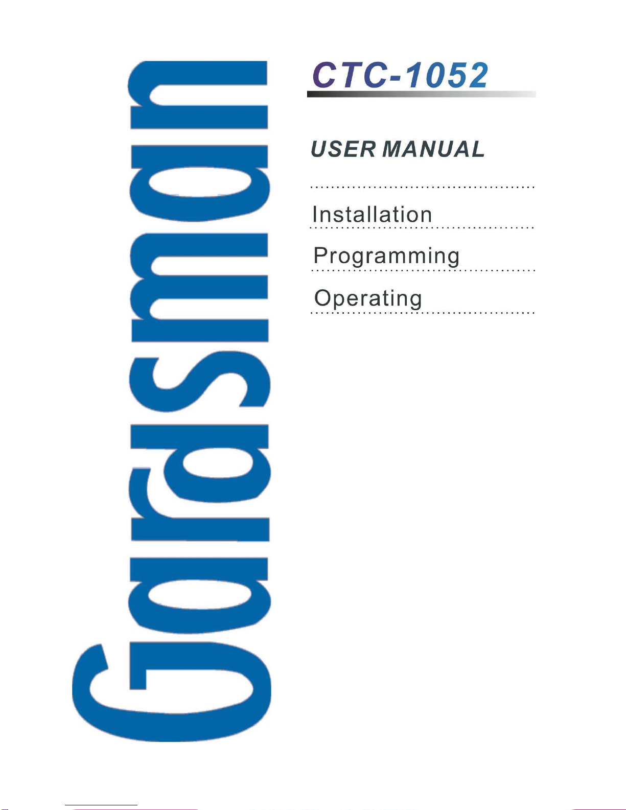
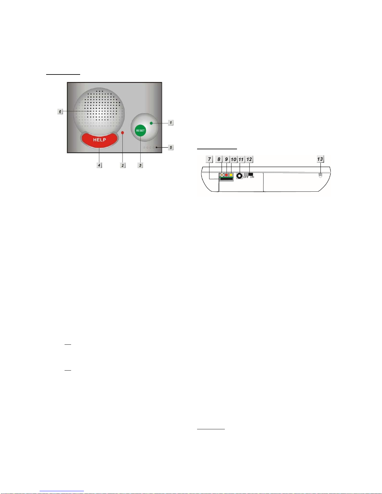
Step 1. Plug in the telephone set into LOCAL
PROGRAMMING input located on the
rear side of CTC-1052.
Step 2. Pick up the handset.
RED LED lights up.
Step 3. Enter default ACCESS CODE, 1111
followed by #.
Step 4. CTC-1052 will emit 2 short beeps and
the red LED starts to flash, indicating it
is in Programming Mode.
Step 5. Proceed to program system by
referring to the Commands in section
3.2 Programming Your 1052.
<NOTE>
Local programming is prohibited when
AC Power fails.
The first digit of Access Code must be
entered within 15 seconds, otherwise
CTC-1052 will exit automatically.
Failure to enter the correct Access
Code within 2 minutes will cause CTC-
1052 to exit the Programming mode
automatically.
To exit Programming mode, enter 99
followed by #, or place the handset on
hook, or disconnect the Programming
telephone set.
3.1.2. CTC-835 Programmer
CTC-835 is a powerful programming tool (sold
separetely) that features a built-in keypad and
LCD display to help you to program the medical
alarm panels effeciently and conveniently. It
also features Once-for-All Uploading, which
allows you program on a computer via the
supplied Pilot software and you can then upload
all the settings to the medical alarm panel
simultaneously with a single mouse click.
For detailed usages, please refer to the
Operation Manual of CTC-835 Programmer.
3.1.3. Remote Programming Mode
To allow Remote Programming, there are two
options for CTC-1052 to answer the incoming
calls.
(1) Auto Answering by ring count
(2) Dial in twice (Ring Count disable)
The two options are set by Command #41.
Please refer to Command 41 under section 3.2
Programming Your 1052.
3.1.3.1. Auto Answering by Ring Count
By using Command 41, you can set the number
of rings for CTC-1052 to answer (00-Rings is
set as factory default).
Step 1. Dial CTC-1052 and wait for CTC-1052
to answer.
Step 2. Enter 1111 (default 4-digit Access
Code) followed by #, via the phone set.
Step 3. CTC-1052 will respond with two quick
beeps to indicate it is ready for Remote
Programming. The RED LED will flash
as a visual indication.
Step 4. You are now in Programming Mode.
Proceed to program by referring to the
Command under section 3.2
Programming Your 1052.
3.1.3.2. Dial in Twice (Ring Count Disable)
As 00 is set in Command 41 by default, it means
CTC-1052 is disabled to auto answer the
incoming calls by ring count. If Remote
programming is required, you will need to call
CTC-1052 twice.

6
Step 1. Dial CTC-1052 and hang up after first 2
rings, wait for another 8-20 sec then
call again. CTC-1052 will answer the
call on the first ring. You will enter the
Remote Programming Mode after the
first ring from the 2nd call.
Step 2. Enter 1111 (the default 4-digit Access
Code) followed by #, via the phone set.
Step 3. CTC-1052 will respond with two quick
beeps to indicate it is ready for Remote
Programming Commands. The RED
LED will flash as a visual indication.
Step 4. You are now in Programming Mode.
Proceed to program by referring to the
Command in section 3.2
Programming Your 1052.
<NOTE>
The first digit of Access Code must be
entered within 15 seconds; otherwise
CTC-1052 will exit automatically.
To exit Remote Programming mode,
enter 99 followed by #.
3.1.4. SMS Remote Programming
CTC-1052 can be remotely programmed via
SMS commands. Please refer to section 3.3
SMS Remote Programming for usage.
3.2. Programming Your 1052
How to enter Commands?
Please make sure CTC-1052 is in
Programming Mode (RED LED flashes
continuously) before trying any CTC-1052
Command Functions. Please refer to section
System Configuration, Entering
Programming Mode.
Follow the protocol below to command
CTC-1052:
1. CC = 2-digit DTMF Command
2. # = Termination of the DTMF Command
3. ACK = DTMF Command
Acknowledgement
On CTC-1052:
Short beep: Command succeeded
Long beep: Command failed
On the programming phone set:
Short beep: Command succeeded
Long beep: Command failed
4. Function Selection = According to different
Command you will have different entering in
this part, e.g. Tel. Number, Account number,
etc.
5. # = Terminates Function Selection
6. ACK = Function Selection
Acknowledgement
On CTC-1052:
Short beep: Command succeeded
Long beep: Command failed
On the programming phone set:
Short beep: Command succeeded
Long beep: Command failed
CC #DTMF
ACK
Function
Selection
#DTMF
ACK
1. 2. 3. 4. 5. 6.

7
Follow the Command Steps to program
your CTC-1052:
Step 1. Enter Command number (DTMF
Numeric Command, ex. (01), (02)…)
Step 2. Press (#) to terminate the DTMF
Command.
Step 3. One short beep will be heard for
successful Command entry.
Step 4. Enter the desired Command function
number.
Step 5. Enter (#) to terminate the Command
Operation.
Step 6. CTC-1052 will emit a short beep,
indicating successful programming.
The maximum interval between key strokes is 2
minutes. Otherwise, commands will be ignored
and CTC-1052 will automatically exit to Idle
Mode.
Any erroneous programming must be
rectified and program again correctly.
Command 01-04
Telephone Number Programming
Used to program the 1st - 4th Tel. numbers
respectively.
To program the 1st Tel. number: enter (01)
followed by (#). After one short beep, enter
(telephone number) followed by (#).You
can hear one beep from the telephone
speaker that indicates the programming is
successful.
If you hear CTC-1052 emit one beep
instead, that means the programming of the
1st telephone number has failed. Please
repeat the programming steps again.
Likewise, the 2nd, 3rd or 4th Tel. numbers can
be programmed using Command (02), (03)
or (04) respectively.
<NOTE>
When entering the phone number,
entering () means a 3-second pause.
(e.g. Switchboard system, extension,
etc.). For example, the phone number
is 21111111 and extension number is
255. Enter: 21111111*255.
Up to 20 digits including () are
allowed for each telephone number.
Delete Telephone Number:
To delete the 1st Tel. number, enter (01)
followed by (#), after one short beep, enter
another (#). You can hear one beep from
the telephone speaker that indicates the
telephone number has been successfully
deleted.
If you hear CTC-1052 emit one beep
instead, that means you have failed to
delete the telephone number. Please repeat
the deleting steps again.
Likewise, you can erase the respective 2nd,
3rd or 4th Tel. Numbers, by following the
above procedure.
Command 05-06
Select Telephone Number for Alarm
Reporting and Status Reporting
<IMPORTANT NOTE>
If the Tel. number is selected in
Commands #5, #6 and #7, then
Command #7 holds the top priority to
overwrite the setting. The Tel. number
selected in Command #7 will not be used
for alarm and/or status reporting.
Command (05): Select which telephone
number & GPRS/IP (1-6) is/are to be used
for Alarm Reporting.
Command (06): Select which telephone
number & GPRS/IP (1-6) is/are to be used
for Status Reporting.
Available Key-in options:
Tel. Number /
IP Address
Function Selection
Sequence
1st Tel. # (1)
2nd Tel. # (2)
3rd Tel. # (3)
4th Tel. # (4)
5th GPRS1 # (5)
6th GPRS2 # (6)

8
1st & 2nd Tel. #s (12)
1st & 3rd Tel. #s (13)
1st & 4th Tel. #s (14)
1st Tel & 5th GPRS. #s (15)
1st Tel & 6th GPRS. #s (16)
2nd & 3rd Tel. #s (23)
2nd & 4th Tel. #s (24)
2nd Tel & 5th GPRS. #s (25)
2nd Tel & 6th GPRS. #s (26)
3rd & 4th Tel. #s (34)
3rd Tel & 5th GPRS. #s (35)
3rd Tel & 6th GPRS. #s (36)
4th Tel & 5th GPRS. #s (45)
4th Tel & 6th GPRS. #s (46)
5th & 6th GPRS. #s (56)
1st, 2nd & 3rd Tel. #s (123)
1st, 2nd & 4th Tel. #s (124)
1st , 3rd & 4th Tel. #s (134)
2nd, 3rd & 4th Tel. #s (234)
1st, 2nd, 3rd & 4th Tel. #s (1234)
1st, 2nd, 3rd, 4th Tel. & 5th
GPRS. #s
(12345)
1st, 2nd, 3rd, 4th Tel. 5
th &
6th GPRS. #s
(123456)
Factory default is set as (123456). Alarm &
Status will be reported to all of 4 Telephone
Numbers+2 GPRS (IP).
<NOTE>
The Tel. number selected in Command
#7 will not be used for alarm and/or
status reporting, even if it is selected in
command #5 and/or #6.
When multiple Tel. numbers are
selected, CTC-1052 will always dial in
respective programmed order.
The latest Command (05-06) setting(s)
will overwrite any previously enter
setting(s).
When CTC-1052 reports, GPRS has
the highest priority.
Command 10-14
Account Number Programming
Commands (10-14) are used to set the
account number for the telephone numbers
used for Digital Reporting.
Command (10): Set the same account
number for all telephone numbers. and 5th
& 6th GPRS. #s
Command (11-14): Set the account
numbers for the 1st-4th Tel. numbers used
for Digital Reporting respectively.
In (Function Selection) key in 4 or 6 or 8
digit Account Number.

9
Command 20-24
Reporting Method
Commands (20-24) are used to program
the Alarm reporting method for each Tel.
Number.
Command (20): Program the same Alarm
Reporting Method for all 4 Tel. Numbers.
Command (21-24): Program the alarm
reporting method for the 1st-4th Tel.
Numbers respectively.
Available Options:
(0), Contact ID, is set as factory default for
all 4 telephone Numbers.
<NOTE>
The latest Command (20-24) setting(s)
will overwrite any previously entered
setting(s).
If any of Digital Reporting Methods
is selected:
Once alarm or emergency data is
successfully transmitted, CTC-1052 will
automatically enter specific Follow-On
and/or Call Back Mode as specified by
Command (38).
If Speech Method is selected:
After the dialing for alarm/emergency
trigger is successful, CTC-1052 opens
a two-way voice communication
between the Call Recipient and CTC-
1052 for 1-10 minutes (set by
Command #46).
If the Call Recipient needs more talk
time, they can press any keys except 9
or 0 on their phone set to reset to the
original communication duration (set by
Command #46).
To terminate the call, press (9) or
RESET BUTTON on CTC-1052.
During the Speech period, CTC-1052
will emit two beeps via the telephone
handset to alert the call recipient the
remaining time of 20 & 10 secs.
Speech Reporting made under Silent
Mode (set by Command #35) will
automatically be switched to Listen-in,
but call recipient can press DTMF keys
to open two-way communication or
change modes.
If any of SMS Reporting Methods is
selected:
CID sent over SMS is a backup path
when alarm can’t go through in digital
reporting method. Once alarm or
emergency data is successfully
transmitted, the CTC-1052 will
automatically send out a SMS (CID)
Message.
Command 31
Ringer Enable for Incoming Calls
CTC-1052 can be programmed to emit a
ring tone as an audio alert, or silent for
incoming calls.
Function Selection Result
(0) OFF (Ring Tone Disable)
(1) ON (Ring Tone Enable)
Factory Default is set as (0), OFF.
If the function is set to ON, you can answer
the incoming call by pressing the Active
button of WTR, PB, or Fall Sensor, or the
Red Help Button on CTC-1052.
The time-out period for the incoming call is
30 minutes.
To terminate the incoming call, either press
the Active button of WTR, PB, or Fall
Sensor, or press the Green Reset Button
on CTC-1052.
During the AC Power failure period, Ring
Tone is automatically disabled.
Method Function
Selection
Digital
Reporting
Method
(0) Contact ID
(1) Scancom
(2) Tunstall
Speech
Method (3) Open Two-way
communication
SMS
Reporting
Method
(4) SMS (CID)

10
Command 32
Audible Fault Alert
CTC-1052 can be programmed to emit
Fault Alert Beeps every 30 seconds from
AC Failure.
Function Selection Result
(0) OFF
(No Warning Beep)
(1) ON
(With Warning Beep)
Factory Default is set as (0), OFF.
Command 33
Help Arrived Signaling
This function is available for Digital
reporting, SMS reporting and GPRS
reporting methods.
It is used for the Monitoring Center
personnel to confirm if the help has arrived
for the user or not.
This function will be activated after
successfully reported from the following
situations:
Pressing the Red Help Button on
CTC-1052.
Pressing the Active button on WTR,
PB or Fall Sensor is pressed.
A fall detection.
If Help Arrived Signaling is set to ON, once
the Alarm Reporting is completed, the Red
Help Button will start to flash as the panel
enters Help Arrived Mode.
If Help Arrived Signaling is set to OFF,
CTC-1052 will return to idle mode when
Alarm Reporting is completed.
Function Selection Result
(0) OFF
(Disable)
(1) ON
(Enable)
Factory Default is set as (0), OFF.
<NOTE>
If the Green Reset Button is not
pressed within the period set by
Command 67 (Help Arrived Timer),
CTC-1052 will send the alarm report to
summon help again and inform the
Monitoring Center that no help has
arrived within the period set by the Help
Arrived Timer.
Command 33 (Help Arrived Signaling)
has to be set as ON for Command 67
(Help Arrived Timer) to be activated.
If help has not arrived after sending the
alarm report for 4 times, CTC-1052 will
dial the telephone number set by
Command 75 and open two-way
communication when the call is
answered.
Command 34
Emergency Button Enable
The Red Help Button can be enabled or
disabled to send an Emergency alarm
report:
Function Selection Result
(0) OFF
(Disable)
(1) ON
(Enable)
Factory Default is set as (1), ON.
OFF: Pressing the Red Help Button is
unable to send an emergency alarm.
ON: Pressing the Red Help Button will
activate the panel send an emergency
alarm.

11
Command 35
Silent Mode
CTC-1052 can be selected to operate in
Silent Mode. This will mute all normal
operation warning beeps, guard time
tone and key tone.
<NOTE>
Speech Reporting made under Silent
Mode will automatically be switched to
Listen-in, but call recipient can press
DTMF keys to open two-way
communication or change modes.
If Command #31 is set as Enable,
CTC-1052 will emit ring tone for
incoming calls even in silent mode.
Silent mode will not mute the long beep
emitted during walk test.
Function
Selection Result
(0) ON (Silent)
(1) OFF (Normal)
Factory Default is set as (1), OFF.
Command 37
AC Fault Report
The CTC-1052 can be programmed to send
a Fault Report when an AC power failure is
detected.
Function Selection Result
(0) OFF
(Send No Report)
(1) ON
(Send Report)
Factory Default is set as (1), ON.
<NOTE>
Reporting will only be made after
detecting AC Fault condition
continuously for one hour.
Command 38
Follow-On & Call-Back Function
The Command is available for Digital
Reporting Methods (when Command #20 -
#24 is set as (0), (1) or (2))
Function Selection Result
(0) Follow-On
(1) Call-Back
(2) Follow-On & Call-Back
Factory Default is as (0), Follow-On.
When this function is programmed as (0),
after a successful reporting to the
Monitoring Center, CTC-1052 will
automatically enter the Follow-On mode as
specified by Command (45).
When this function is programmed as (1),
after a successful reporting to the
Monitoring Center, CTC-1052 will
automatically hang up the line and start a 5-
minute waiting period to auto answer any
incoming phone calls from the Monitoring
Center.
When this function is programmed as (2),
after a successful reporting to the
Monitoring Center, CTC-1052 will
automatically enter the Follow-On mode as
specified by Command (45).
Once Follow-On Mode is terminated, CTC-
1052 will automatically start a 5-minute
waiting period to auto answer any incoming
phone calls from the Monitoring Center.
When the Monitoring Center calls back
within the 5-minute period (when call back
function is enabled), CTC-1052 will auto-
answer the call after the 1st-2nd ring and
waits for Access Code (default is 1111) and
the (#) key entry within 15 seconds.
When the correct Access Code is received,
CTC-1052 will then open a Full-Duplex
Communication to allow the Call Recipient
to speak to CTC-1052 directly.
You can use DTMF command to switch the
communicating method. Please refer to
section 4.2. Alarm Activation.
<NOTE>
The Access Code must be entered

12
within 15 seconds. Otherwise, CTC-
1052 will disconnect the call
automatically.
To terminate the call, press DTMF (9),
(0) or Green Reset Button on CTC-
1052.
If the 5-minute waiting period is up,
CTC-1052 will automatically exit this
waiting mode and return to idle mode.
Command 40
Set Access Code
The Access Code is used to enter
Programming Menu (locally or remotely),
and the Call-Back Function.
It consists of 4 digits and has been set to
(1111) as factory default. Before you set
your own Access Code, (1111) must be
keyed in.
To set a new Access code; enter the
desired (4-digit number) in Function
Selection.
Command 41
Auto Answer for Remote Programming
CTC-1052 can be programmed to auto
answer incoming phone calls after a pre-set
number of rings have been reached. The
number of rings range from (00) (no auto
answer) to (32) rings.
Function Selection Result
(00) OFF
(01) - (32) ON
Factory Default is (00) Rings.
<NOTE>
When (00), it means CTC-1052 cannot
auto-answer the call by ring count. If
you want to do Remote programming,
please follow the Remote Programming
method described in 3. System
Confguration, 3.1. Entering
Programming Mode, 3.1.3 Remote
Programming Mode.
Command 42
Guard Time Delay
This command is designed for any
compatible sensor, except Fall Sensor
(fall detection).
Guard Time Delay time is a time period
programmed to delay alarm reporting. If a
false alarm is raised, it can be cancelled
within this Guard Time Delay time.
The programmable delay time range from
(00) (instant reporting) to (99) seconds.
Emergency alarms activated by Smoke
Detectors (SD), Carbon Monoxide
Detectors (CO), and Water Sensors (WS)
do not have Guard Time Delay and will be
reported immediately.
Function Selection Result
(00) INSTANT REPORTING
(01) - (99) DELAY
Factory Default is (10), 10 SECONDS.
Alarm activated by pressing a button
cannot be cancelled after the Guard Time is
elapsed.
<NOTE>
The Guard Time Delay time from
pressing the Active Button on a Fall
sensor is determined by Command #42
instead of Command #66.
The Guard Time Delay from a fall
detection (of a Fall Sensor) is set by
Command #66.

13
Command 43
Periodic Test Call
CTC-1052 can be programmed to make test
calls periodically from (00) (no test call) to
every (1) - (7) or 30 days:
Function Selection Result
(0) OFF
(1) - (7) 1 - 7 DAYS
(8) 30 DAYS
Factory Default is set as (0), OFF.
<NOTE>
Whenever programming mode is
accessed, CTC-1052 will reset the
Periodic Test Call timer.
Periodic Test Call will only function with
telephone numbers assigned to Digital
or SMS reporting method in Command
20-24.
Command 44
Mobility Timer
This function monitors user movement around
the premises and sends an inactivity report to
the Monitoring Center if the user fails to reset
the inactivity timer.
This will disable or enable the Inactivity
Timer with selectable count down periods.
Options are:
Function Selection Result
(00) DISABLE
(01) 1HR
(02) 2HR
..........
.........
(36) 36HR
Factory Default is set as (00), DISABLE.
<NOTE>
The Mobility Timer counting down can
be reset by:
1. Pressing the Green Reset Button
on CTC-1052, or,
2. Movement detected by PIR
Detector
3. Only workable by entering 2 digits.
When Mobility Timer expires and no
reset signal is received, CTC-1052
starts to emit one long beep every 5
minutes to alert the user. (You can
enable or disable long beep sound, see
Command 78 for details).After 30
minutes, if reset signal is not received,
a mobility alarm reporting will be made.
The reporting method for mobility alarm
is the same as the emergency alarm.
The report will be sent based on your
reporting methods without guard time
waiting.
When (00) is selected, no code is sent
to Monitoring Center.
When CTC-1052 is in idle mode, press
and hold the Green Reset Button for
16 seconds, until you hear a long beep.
Release the button and the Mobility
function will be disabled.

14
Command 45
Follow-On Mode Choice
This Command is only available for Digital
reporting with Command #38 set as (0) or
(2).
It is used to select the Follow-On Choice for
CTC-1052 after it has made a report to the
Monitoring Center.
After reporting, CTC-1052 can wait for
further commands, or enter a Two-Way Full
Duplex Communication, or Listen-In Half
Duplex Communication immediately
according to the setting selection:
Function Selection Result
(0) WAIT COMMAND
(1) LISTEN
(2) TWO WAY
Factory Default is set as (2), TWO WAY.
When (0) is selected, after CTC-1052 has
made a report to the Monitoring Center, it
will wait for 1-10 minutes (set by Cammand
46), and then follows the DTMF commands
that are received from the Central
Monitoring Station for action.
If no command is received after the waiting
period, the system will automatically return
to Idle mode.
When (1) is selected, after CTC-1052 has
made a report to the Monitoring Center, it
will automatically enter Listen-In Half
Duplex for 1-10 minutes (set by Command
46) allowing the Monitoring Center
Personnel to listen in to what is happening
on the other side.
When (2) is selected, after CTC-1052 has
made a report to the Monitoring Center, it
will immediately enter a Two-way Full-
duplex Communication mode for 1-10
minutes (set by Command#46), that gives
the user the ability to speak directly with the
Monitoring Center Personnel.
<NOTE>
If either Scancom or Tunstall reporting
format is selected, CTC-1052 will ignore
Command#45 selections. It will always
open a Two-way voice for Follow-On
choice.
Command 46
Follow-On Mode & Two-Way Period
This command is used to program the
allowable time duration for Follow-On mode
choice (Command #45) & Two-way voice
communication period (Speech mode). It
can be set from (01) (1 minute) - (10) (10
minutes).
Function Selection Result
(01) 1 MINUTE
(02) 2 MINUTES
(03)-(10) 3-10 MINUTES
Factory default is set as (05), 5 minutes.
The allowable time duration for either Wait
Command, Two-way, Listen-In Only or
Two-way voice comminucation in
Speech mode is 5 minutes. During the 5-
minute period, CTC-1052 will emit two
beeps via the telephone handset to alert
the call recipient the remaining time of 20 &
10 seconds. Press any DTMF key except
the hang up key to reset the communication
time to its preset duration.
Command 47
Off-Set Time
After the Control Panel‘s power is supplied,
the time of the Check-in Report starts
calculating.
According to the setting of Off-Set Time, the
Control Panel will send Check-in Report
once, and then send report according to the
setting of Command 43 - Test call.
Function
Selection Result
(1) 1 Hour
(2) 2 Hour
(3) 3 Hour
(4) 4 Hour
(5) 8 Hour
(6) 12Hour

15
Factory default is set as (1) 1 Hour. When
the Off-Set Time is reset in programming
Mode, the time of the Off-Set period will
recalculate.
Off-Set time Report will be sent only once,
and then the Control Panel sends Check-in
Report according to setting of period test
call, unless the Control Panel restarts or the
Off-Set time is reset.
<NOTE>
Whenever programming mode is
accessed, CTC-1052 will reset the Off-
Set timer.
Command 49
Supervision
This function is not available for the digital
Scancom reporting method.
This option is used to enable system
Supervision function. Once enabled, CTC-
1052 will be able to receive the check-in
signals from Wrist Pendants (WTR) to
indicate their proper functioning.
Function
Selection Result
(0) Disable
(1) 4 Days
(2) 5 Days
(3) 6 Days
(4) 7 Days
(5) 8 Days
(6) 9 Days
(7) 10 Days
Factory default is set as (0) Disable. No
code is sent to Monitoring Center.
When the supervisory timer expires and no
supervision signal is received from WTR ,
CTC-1052 will send a Supervisory Failure
report.
Supervisory Failure is a status report.
Command 61
Check SIM Card PIN Code
This option is used to check SIM card PIN
Code.
Function Selection Result
(0) OFF (Disable)
(1) ON (Enable)
Factory default is set as (0) OFF.
<NOTE>
If this function is disabled, the system
will not check the entered SIM Card PIN
Code set by Command 62.
If the SIM card PIN Code is entered, be
sure to enable this function.Otherwise,
the SIM card will be locked.
Command 62
Input SIM Card PIN Code
This function is used to input SIM card PIN
Code to access the mobile service.
Program the panel to input SIM card PIN
code by entering a 4-8 digit SIM card PIN
code.
Factory default is set as (Null).
Command 62 is functional only when the
SIM card PIN code is activated and when
Command 61 is enabled.
When the SIM card requires the PIN code to
access the mobile service, please make
sure Command 61 is set as ON, enabled,
and that the PIN code set by Command 62
is exactly the same as the SIM card PIN
code.
If the SIM card PIN code is not required,
CTC-1052 can receive calls normally
regardless of the settings of Commands 61
and 62.
Please set the SIM card PIN code correctly
before putting in another SIM card to
prevent locking the SIM card.
Follow the steps below to changing a SIM
card without locking:
Step 1. Enter local programming mode (SIM

16
card module is disabled during this
time).
Step 2. Remove the old SIM card and insert
a new SIM card.
Please DO NOT remove the SIM
card except when the Control Panel
is turned off or is in local
programming mode to prevent errors
or malfunctions.
Step 3. Setup the new SIM card PIN code
using Command 62.
Step 4. Exit local programming mode. The
SIM card module will start up and
attempts to activate the SIM card by
entering the SIM card PIN code.
<NOTE>
This function is not used to change the
SIM card PIN code. If you want to
change your SIM card PIN code, please
use a mobile phone to change it.
If the SIM card is locked, please contact
your local telecommunications service
provider.
Command 63
Speaker Volume Adjustment
This function is used to adjust speaker
volume. To set speaker volume in different
communication channels, please set
different parameters.
Function Selection Result
(2) Two-way
To set speaker volume in two-way modes,
the sequence is:
Communication
Channel
DTMF Speaker Volume
2 * 1 to 5
* Communication Channel: 1 digit ( 2: Two-way)
* Be sure to put * between communication channel value
and speaker volume value.
To set the speaker volume with a number,
ranging 1 to 5. The higher the value, the
louder the voice. Factory default is set as
(3) for Two-Way mode.
Please refer to programming command
table section for configuration.
Example: if you want to raise the speaker
volume to level 5 in the Two Way mode,
please enter: 2*5
<NOTE>
The volume value in the Listen In or Talk-
Only mode is adjusted for the best
communication quality. It is fixed and can
not be changed.
Echo volume varies depending on
adjustment of speaker volume and
microphone sensitivity. To minimize the
impact of echo, if you raise speaker
volume, please be sure to lower
microphone sensitivity, and vice versa.
Command 64
Microphone Sensitivity Adjustment
This function is used to adjust microphone
sensitivity. The microphone sensibility only
can be adjusted in the two-way mode.
To set the microphone sensitivity with a
number, ranging 1 to 5. This value
represents the received sound source
range. The higher the value, the wider range
of sound source. Factory default is set as
(3).
Please refer to programming command table
section for configuration.
<NOTE>
The sensitivity level in the Listen In or
Talk-Only mode is adjusted for the best
communication quality. It is fixed and can
not be changed.
Echo volume varies depending on
adjustment of speaker volume and
microphone sensitivity. To minimize the
impact of echo, if you raise speaker
volume, please be sure to lower
microphone sensitivity, and vice versa.
Command 66
Set Guard Time Delay Time for Fall
Sensor
This command is used to set the Guard
Time Delay time for fall sensor.
CTC-1052 can be programmed to delay
alarm reporting triggered by a fall detection
from (00) (instant reporting) to (99) seconds.

17
During this time period, a continuous series
(1 beep every 0.5 second) of beeps will be
emitted to alert user.
If a false alarm is triggered by a fall
detection, it can be cancelled within the
Guard Time Delay by pressing the Active
Button of the Fall Sensor for 4 seconds.
Function Selection Result
(00) INSTANT REPORTING
(01) - (99) DELAY
Factory Default is (15), 15 SECONDS.
<NOTE>
This command is used if a fall is
detected.
If an emergency alarm is triggered by
pressing the Active Button on Fall
sensor, the guard time delay time is
determined by Command 42.
Command 67
Setting the Help Arrived Timer
This command is used to set the countdown
timer for CTC-1052 to resend the alarm
report if no help has arrived after the initial
report is made (meaning the reset button
has not been pressed before the timer
expires).
Function Selection Result
(01)-(15) 1-15 MINUTES
Factory default is (15), 15 MINUTES.
<NOTE>
The Help Arrived function (Command 33)
must be set as ON for this function to
work.
Command 71-72
Auto-Answer Numbers #1 & #2
Used to program the 1st & 2nd Auto-Answer
Numbers 1 and 2 respectively.
To program Auto-Answer Number 1: enter
(71) followed by (#). After one short beep,
enter (telephone number) followed by (#).
If the number is successfully programmed,
the telephone handset will emit one short
beep.
If the number is unable to be programmed,
the Control Panel will emit one long beep.
Auto-Answer Number 2 can be programmed
using the same method, except command
(71) is replaced by (72).
<NOTE>
Up to 20 digits including () are
allowed for each telephone number.
Delete Telephone Number:
To delete Auto-Answer Number 1, enter (71)
followed by (#), after one short beep, enter
another (#).
If the number is successfully deleted, the
telephone handset will emit one short beep.
If the number is unable to be deleted, the
Control Panel will emit one long beep.
Auto-Answer Number 2 can be erased using
the same method, except command (71) is
replaced by (72).
Command 75
Help Not Arrived Call
If help has not arrived after sending the
alarm report for 4 times, CTC-1052 will dial
the telephone number programmed by
Command 75 and open two-way
communication when the call is answered.
Enter a telephone number followed by (#)
to program the telephone number.
<NOTE>
When you program the phone number,
entering () will cause a 3-second
pause is for a switchboard system,
extension, etc.
The telephone number can contain up
to 20 digits, including ().
The Help Arrived function (Command
33) must be set as ON for this function
to work.
CTC-1052 only dials this telephone
number once. If this phone call fails,
CTC-1052 will not try again.
Table of contents
Popular Medical Equipment manuals by other brands

I-Tech
I-Tech Power Q-6000 Plus user manual

Invacare
Invacare ROZE user manual

Verathon
Verathon BladderScan i10 Operation & maintenance manual

Zhermack
Zhermack Doublemix user manual

Top shelf Orthopedics
Top shelf Orthopedics Crusader ACL Instructions for use

HealthSmart
HealthSmart 522-9821-1900 instructions