4
2. Learn-in the Devices
There are two methods to learn in the device:
1. Use Learning mode, you can learn in
Pendant #1 and Pendant #2.
2. Use Command #91 - #92 in Programming
mode to learn WTR- series (except WTRV).
For learning silent pendant, use Command
93 to learn it. To add other devices,
including PIR Sensor, Smoke Detector,
Panic Button, Carbon Monoxide, Wrist &
Neck Transmitter, Water Sensor, and
Pendant Transmitter, WRT- series (except
WTRV), please use Command 94. For
details, please refer to section 3.2
Programming Your 1052RV: Commands
91-94.
3. Only 10 devices are allowed to be learnt in.
<
<N
NO
OT
TE
E>
>
)Only one WTRV can be learn into
CTC-1052RV.
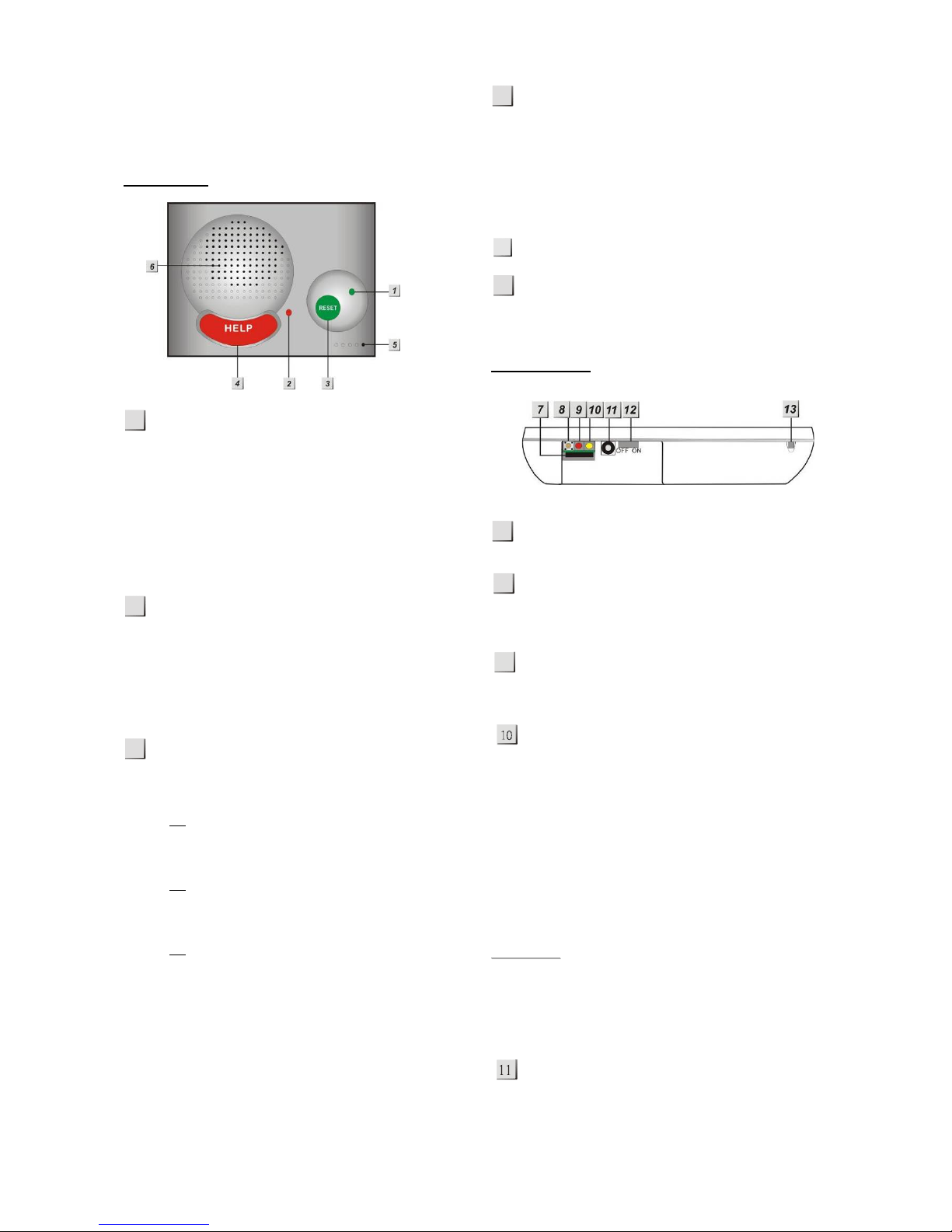
2.1. Learning Pendant #1
When CTC-1052RV enters the Learning Mode,
you can learn WTR- or WTRV as the following
steps:
For Normal Wrist Transmitters (WTR-)
Step1. Press and hold the RESET button of
CTC1052RV for 6 seconds. Release
the button after you heard the double
beep. Then, release the button and a
long beep will be heard. The RED
LED begins to flash to indicate that
the CTC-1052RV is now in Learning
Mode.
<
<N
NO
OT
TE
E>
>
)Once pressed, a button beep sound
will be heard. CTC-1052RV will emit
one short beep at 3 sec, then a double
beep when it reaches 6 sec.
Step2. Press and both the RESET and
Pendant #1 buttons simultaneously
until CTC-1052RV emit a double-beep
to indicate that the Pendant #1 has
been learnt-in successfully.
For Talking Pendant (WTRV)
Step1. Press and hold the RESET button of
CTC-1052RV for 6 seconds. Release
the button after you heard the double
beep. After releasing the button, a
long beep will be heard. The RED
LED begins to flash to indicate that
the CTC-1052RV is now in Learning
Mode.
<
<N
NO
OT
TE
E>
>
)Once CTC-1052RV is pressed, a
button beep sound will be heard. It will
emit one short beep at 3 sec, then a
double beep when it reaches 6 sec.
Step2.Press and hold the WTRV
ACTIVE/PEDNANT button for 5
seconds. The WTRV’s Green LED turn
to RED. When hearing a long beep,
release the WTRV button. The WTRV
is now in the learn mode.
Step3. Press and hold the reset button on
CTC-1052RV for 20 seconds and
meanwhile the WTRV’s LED will turn
from RED, then blink green to steady
green. When you hear two beeps and
then one long beep emitted from CTC-
1052RV, release the RESET button
from the CTC-1052RV. The learning
process now is successful.
Step 4. To check if the WTRV is successfully
learnt in, press the WTRV ACTIVE
button. If you hear 6 continuous beeps
from WTRV and meanwhile the Control
Panel respond two shorts beeps
respectively, it indicates that the WTRV
is successfully learnt in. If you don’t
hear any corresponding beep from
Control Panel after pressing the WTRV
ACTIVE button, it indicates that the
learning process fails. Turn the Pedant
off and repeat the steps mentioned
above until you hear the CTC-
1052RV’s corresponding beeps.
Step 5. If there is a 2nd Pendant (Pendant #2)
wished to be learnt-in, proceed to
Steps 1 & 2 under the section of For
Normal Wrist Transmitter(WTR-) in
2.1 Learning Pendant #1, but the
Reset button should be changed to
Help Button instead.