waratah HTH616C SIII User manual

HTH616C SIII
Harvester Head
WA135210 31MAY22 (ENGLISH)
COPYRIGHT® 2022 WARATAH NZ LIMITED
Tokoroa, New Zealand All Rights Reserved
LITHO IN NEW ZEALAND
Operator’s Manual

Page
General
Foreword ...................... .. .. .. .. .. .. .. .. .. .. .. .. 0-1-1
Copyright ....... .. .. .. .. .. .. .. .. .. .. .. .. .. .. .. .. .. .. .. . 0-1-1
General Information ......................... .. .. .. .. . 0-1-1
Manual Replacement . .. .. .. .. .. .. .. .. .. .. .. .. .. .. .. . 0-1-1
Warranty ....................... .. .. .. .. .. .. .. .. .. .. .. .. 0-1-1
Avoid Unauthorised Machine Modications ... .. .. 0-1-2
Features ....................... .. .. .. .. .. .. .. .. .. .. .. .. 0-1-3
Safety: General Precautions
Read Manuals Before Operating . .. .. .. .. .. .. .. .. .. 1-2-1
Operator Risk ................................ .. .. .. .. . 1-2-1
Wear Protective Equipment ................ .. .. .. .. . 1-2-1
Driving Precautions ......................... .. .. .. .. . 1-2-1
Keep Personnel Off the Harvester Head ......... . 1-2-2
Take Care when Moving the Harvester Head .... 1-2-2
Prevent Debris from Hitting the Cab . .. ... .. .. .. .. . 1-2-2
Carrier Class and Head Type ....................... 1-2-2
Operator Protective Structures ..................... 1-2-3
Inspect the Harvester Head ... .. .. .. .. .. ............ 1-2-3
Prevent Fires ................. .. .. .. .. .. .. .. .. .. .. .. .. 1-2-4
In Case of Machine Fires .................. .. .. .. .. . 1-2-4
Dispose of Waste Properly . .. .. .. .. .. .. .. .. .. .. .. .. . 1-2-4
Safety: Maintenance Precautions
Prepare for Service Safety .. .. .. .. .. .. .. .. .. .. .. .. .. 1-3-1
Service Safety ... .. .. .. .. .. ........................... 1-3-1
Waratah Key Switch Control (Three-position) . .. . 1-3-2
Waratah Switch Control (Two-position) . .. .. .. .. .. . 1-3-3
Lockable battery disconnect switch ....... .. .. .. .. . 1-3-4
To activate manual mode . .. .. .. .. .. .. .. ............ 1-3-5
H-16 Controller Power ...................... .. .. .. .. . 1-3-5
Carrier Reset and Interlock ... .. .. .. .. .. .. .. .. .. .. .. 1-3-5
Hydraulic Repair Safety .. .. .. .. .. .. .. .. .. .. .. .. .. .. . 1-3-6
Welding Repairs Safety ............................. 1-3-6
Accumulator Repair Safety ................. .. .. .. .. . 1-3-7
Slotted Link (Optional Feature) ............ .. .. .. .. . 1-3-7
Chain Shot Guard Inspection .. .. .. .. .. .. .. .. .. .. .. . 1-3-7
Safety: Operation Precautions
General Operation Precautions ... .. .. .. .. .. .. .. .. .. 1-4-1
Avoid Work Site Hazards ... .. .. .. .. .. .. .. .. .. .. .. .. 1-4-1
Avoid Chain Shot .... .. .. .. .. .. .. .. .. .. .. .. .. .. .. .. .. . 1-4-2
Operating Safely .. .. .. .. .. .. .. .. .. .. .. .. .. .. .. .. .. .. . 1-4-3
Processing Safely ... .. .. .. ........................... 1-4-3
Safety: Safety Signs and Labels
Safety Label Explanations .. .. .. .. .. .. .. ............ 1-5-1
Read and Understand Manuals . .. .. .. .. .. .. .. .. .. . 1-5-1
Lock the Tilt Frame . .. .. .. ... .. .. .. .. .. .. .. .. .. .. .. .. 1-5-1
Lock the Pilot Interlock Valve . .. .. .. .. .. .. .. .. .. .. .. 1-5-2
Stay Clear of the Saw Chain .... .. .. .. .. .. .. .. .. .. . 1-5-2
Page
Never Stand on the Harvester Head . ............. 1-5-2
Keep Away from the Pinch Area ... .. .. .. .. .. .. .. .. 1-5-2
Do Not Stare into the Laser Beam ....... .. .. .. .. .. 1-5-3
Beware of Chain shot ............. .. .. .. ... .. .. .. .. .. 1-5-3
Precautions: Processing on the Landing .......... 1-5-4
Precautions: Tree Felling . .. .. .. .. .. .. .. ... .. .. .. .. .. 1-5-4
Do Not Operate Unless Seated ... .. .. .. .. .. .. .. .. . 1-5-4
Take Care With Electrical Welding .. .. ............. 1-5-4
Key Ring Caution and ID .................. .. .. .. .. .. 1-5-5
Cab labels (two-position Waratah switch) .... .. .. . 1-5-6
Operation: General Operation
General Operation .......... .. .. .. .. .. .. .. .. .. .. .. .. . 2-1-1
Planning Area Preparation ... .. .. .. .. .. .. .. .. .. .. .. . 2-1-1
Operation: Clear-cut Harvesting
Felling .... .. .. ............................... .. .. .. .. .. 2-2-1
Felling Process . .. .. .. .. .. .. .. .. .. .. .. .. .. .. .. .. .. .. .. 2-2-1
Delimbing ... .. .. .. .. .. .. .. ............................ 2-2-1
Fall and Delimb ... .. .. .. .. .. .. .. .. .. .. .. .. .. .. .. .. .. .. 2-2-2
Operation: Thinning Techniques
Plantation Out Row .. .. .. ............................ 2-3-1
Select Thinning .. .. .. .. .. .. .. .. .. .. .. .. .. ............. 2-3-2
Operation: Processing
General ....................... .. .. .. .. .. .. .. .. .. .. .. .. . 2-4-1
Debarking .. .. .. .. .. .. .. .. .. .. .. .. .. .. .. .. ............. 2-4-1
Measuring ....... .. .. .. .. .. .. .. .. .. .. .. .. .. .. .. .. .. .. .. 2-4-1
Operation: Cutting
General ....................... .. .. .. .. .. .. .. .. .. .. .. .. . 2-5-1
Using the Main Saw Unit .................. .. .. .. .. .. 2-5-1
Using the Top Saw Unit . ............................ 2-5-1
Operation: Special Techniques
Use of Double Cuts . .. .. .. .. .. .. .. .. .. .. ............. 2-6-1
Quarter Cutting . .. .. .. .. .. .. .. .. .. .. .. .. .. .. .. .. .. .. .. 2-6-1
Falling Multi-leaders . .. .. .. .. .. .. .. .. .. .. .. .. .. .. .. .. 2-6-2
Felling on Hillsides . .. .. .. .. .. .. .. .. .. .. .. .. .. .. .. .. .. 2-6-2
Operation: Miscellaneous
Unattended Harvester Head ... .. .. .. .. ... .. .. .. .. .. 2-7-1
Delimbing Multi-leaders .... .. .. .. .. .. .. .. .. .. .. .. .. . 2-7-1
Maintenance: Fluids and Lubricants
Recommended Hydraulic System Fluid . .. .. .. .. .. 3-1-1
Chain Oil ... .. .................. .. .. .. .. .. ... .. .. .. .. .. 3-1-1
Grease ........... .. .. .. .. .. .. .. .. .. .. .. .. .. .. .. .. .. .. .. 3-1-2
Greasing Procedure . .. .. .. .. .. .. .. .. .. .. .. .. .. .. .. .. 3-1-3
Continued on next page
Original Instructions. All information, illustrations and specications in this
manual are based on the latest information available at the time of publication.
The right is reserved to make changes at any time without notice.
Contents
i

Page
Grease Point Location: Rotator ... .. .. .. .. .. .. .. .. .. 3-1-4
Grease Point Location: Tilt Cylinder . .. ............ 3-1-4
Grease Point Location: Tilt Frame Main Pin .. .. .. 3-1-4
Grease Point Location: Top Saw Unit ............. 3-1-4
Grease Point Location: Upper Delimb Arms . .. .. . 3-1-5
Grease Point Location: Lower Delimb Arm ....... 3-1-6
Grease Point Location: Feed Arms . .. .. .. .. .. .. .. . 3-1-6
Grease Point Location: Length-measuring
Unit ... .. .. .. .. .. .. .. .. .. .. .. .. .. .. .. .. .. ............ 3-1-7
Grease Point Location: Feed Unit ......... .. .. .. .. . 3-1-7
Grease Point Location: Main Saw Unit (3/4"
Saw) ......... .. .. .. .. .. .. .. .. .. .. .. .. .. .. .. .. .. .. .. . 3-1-7
Grease Point Location: Main Saw Unit
(SuperCut 100) .. .. .. .. .. .. .. .. .. .. .. .. ............ 3-1-8
Maintenance: Schedule
Periodic Maintenance Record . .. .. .. .. .. .. .. .. .. .. . 3-2-1
Maintenance: Every 8 Hours or Daily .. .. .. .. .. .. . 3-2-2
Maintenance: Every 50 Hours or Weekly ......... 3-2-2
Maintenance: Every 200–250 Hours or
Monthly ..................... .. .. .. .. .. .. .. .. .. .. .. .. 3-2-4
Maintenance: Every 1000 Hours or 6 Months . .. . 3-2-7
Maintenance: Every 2000 Hours or Annually .. .. . 3-2-7
Maintenance: General
Recommended Harvester Head Positions for
Saw Chain and Saw Bar Maintenance ......... 3-3-1
Fault Finding ... .. .. .. .. .. .. .. .. .. .. .. .. .. .. .. .. .. .. .. . 3-3-1
Unied Inch Bolt and Cap Screw Torque
Values ... .. .. .. .. .. .. .. .. ........................... 3-3-2
Metric Bolt and Cap Screw Torque Values ... .. .. . 3-3-3
Additional Metric Cap Screw Torque Values ...... 3-3-4
Miscellaneous: Carrier
Welding on the carrier or harvester head .. .. .. .. . 4-1-1
Using booster batteries ..................... .. .. .. .. . 4-1-1
Miscellaneous—Measurements
Metric and Imperial Unit Expressions .............. 4-2-1
Miscellaneous: Specication Conversion
Conversion ..... .. .. .. .. .. .. .. .. .. .. .. .. .. .. .. .. .. .. .. . 4-3-1
Miscellaneous: Wood Measurement
Wood Measurement Equivalents . .. .. .. ............ 4-4-1
Contents
ii

Foreword
READ THIS MANUAL carefully to learn how to operate
and maintain your machine correctly. Failure to do so
could result in personal injury or equipment damage.
This manual and the safety signs on your machine may
also be available in other languages. (See your Waratah
dealer to order.)
THIS MANUAL SHOULD ALWAYS remain with the
machine, even if you sell the machine. It provides
detailed operating and maintenance instructions as well
as safety information and equipment data.
MEASUREMENTS in this manual are given in both
metric and imperial equivalents. Use only correct
replacement parts and fasteners. Fasteners may
require a specic metric or inch wrench.
RIGHT-HAND AND LEFT-HAND sides are determined
by facing in the direction of forward travel.
WRITE PRODUCT IDENTIFICATION NUMBERS in the
machine numbers section on page 3-2-1. Accurately
record all numbers to help in tracing the machine should
it be stolen. Your dealer also requires these numbers for
ordering of parts. File the identication numbers in a
secure place off the machine.
WARRANTY is provided as part of Waratah New
Zealand Limited’s (“Waratah’s”) support program for
customers who operate and maintain their equipment as
described in this manual. The warranty is explained
below.
Waratah will back its products where defects appear
within the warranty period. Waratah may also provide
eld improvements at times, often without charge, even
if the product is out of warranty. If the equipment is
abused, or modied to alter its performance from
published specications, the warranty will become void
and eld improvements may be withheld.
T7M7G6M,00004BA-19-10OCT21
Copyright
These original instructions are the property of Waratah
New Zealand Limited.
All information, illustrations, and specications provided
in this manual are based on the latest information
available at the time of publication. We reserve the right
to make changes at any time and without notice.
COPYRIGHT © 2022
WARATAH NEW ZEALAND LIMITED
Tokoroa, New Zealand
All rights reserved.
Issue date: May 2022
T7M7G6M,0000807-19-30MAY22
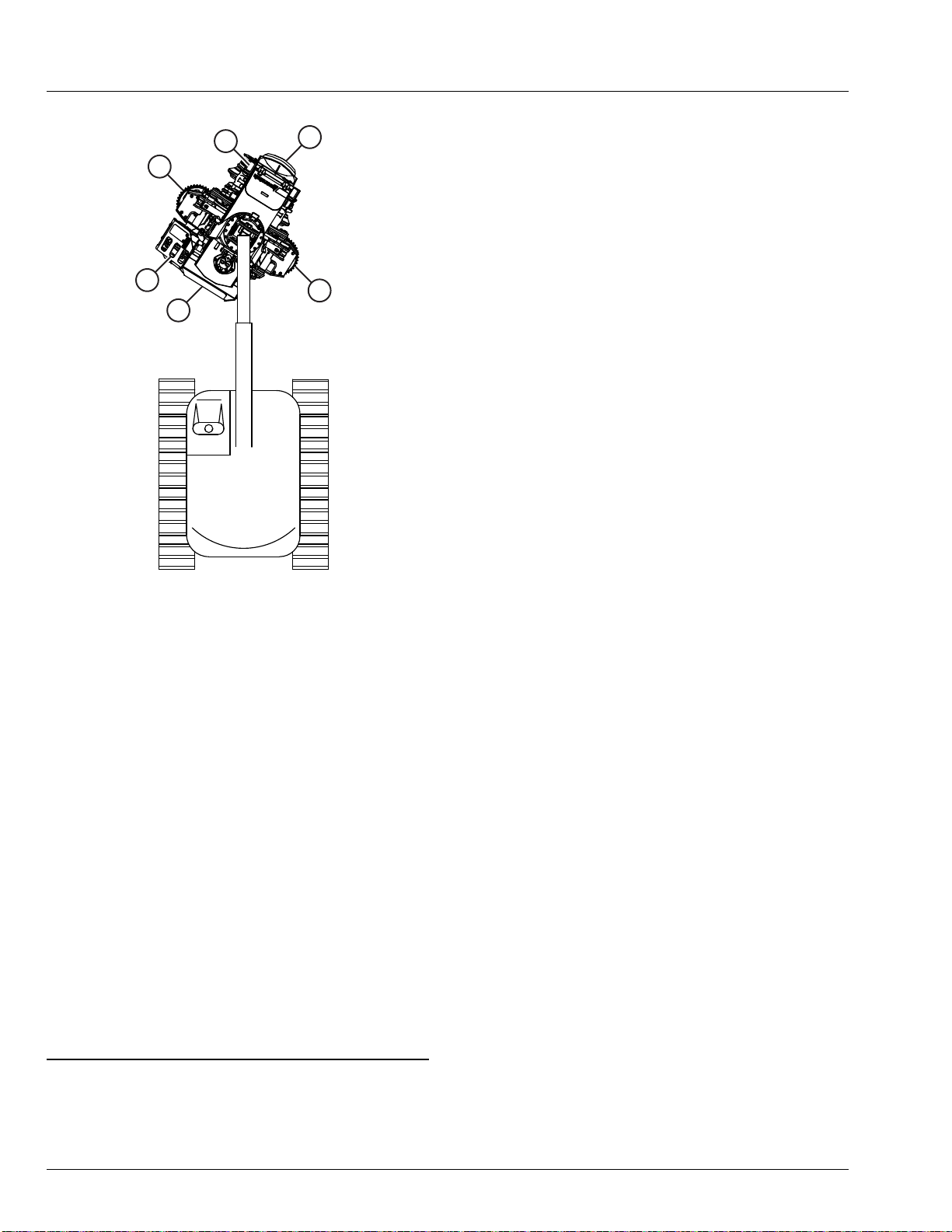
General Information
This manual contains instructions for the maintenance
of the HTH616C SIII harvester head. If you have
questions about the instructions, please consult your
local dealer for more detailed information.
Every effort was made to ensure that the information
contained in this manual was accurate at the time of
publication. Waratah, however, accepts no responsibility
for any errors or consequences arising from them.
Waratah also reserves the right to revise product
specications, instructions, etc. as required by ongoing
product improvements and updates.
All service and repairs should be carried out by qualied
service personnel, or an authorized repair shop with
suitable tools and lifting devices, using Waratah-
approved parts. Waratah takes no responsibility for
damages that may arise through instructions not being
followed or through improper use of the product.
T7M7G6M,0000363-19-18AUG21
Manual Replacement
When re-ordering this manual, quote the part number
“WA135210” and the date of publication.
T7M7G6M,0000364-19-28FEB20
Warranty
Terms: Unless otherwise stated, Waratah New Zealand
Limited (‘Waratah’) warrants each new attachment to be
free of failure caused by defective material or
workmanship for a period of one (1) year or two
thousand (2000) hours, whichever rst occurs, following
date of delivery of the product to the original retail
customer (user).
Warranty coverage for parts on Waratah’s forestry
attachments is for 12 months from the date of
installation by a Waratah-approved dealer, or 180 days
from the date of delivery if the customer buys the part
over the counter.
Interruptions: Only one warranty interruption, lasting
no more than six (6) months, will be accepted during the
warranty period.
Validity: To validate this warranty, attachment
installation must be done by an authorised dealer on a
carrier that meets Waratah’s specications, prescribed
pre-delivery and start-up inspections must be
completed, and the customer must complete, sign, and
submit a Warranty Registration Form to the selling
Waratah Distribution Centre (WDC).
Obligations: Waratah’s sole obligation under this
warranty is limited to repairs of failures due to faulty
workmanship, or the repair or replacement of defective
parts. These actions are without charge, whether in the
eld, or at Waratah’s factory, warehouse, or an
General
0-1-1

approved repair shop. Return freight of parts must be
pre-paid by the user. Waratah is not responsible for any
costs associated with the delivery of an attachment or
its parts for repairs, or any costs associated with the
delivery of parts to make repairs.
Exceptions: This warranty does not apply to software.
It does not apply to maintenance items used in service
(such as lubricating oils and lters) and consumable
parts (such as blades and saw chains). It does not apply
to products that show evidence of neglect, overload,
abuse, accident, or unauthorised alteration. It does not
apply to products that are inadequately maintained or
used for other than their designated purposes, as
dened in Waratah’s technical and marketing
publications.
Annulment: This warranty shall be void if Waratah
determines that the attachment’s performance or
reliability is adversely affected by 1) repairs or
alterations to the product made by persons or rms not
approved by Waratah, or 2) installation of the product on
a machine or by persons or rms not approved by
Waratah, 3) replacement parts that are not genuine
Waratah parts, or 4) failure to follow prescribed
processes in Waratah manuals or on Waratah product
safety labels.
Waratah hereby disclaims liability on its part for
damages, whether general, special, or arising through
negligence, and expressly including any incidental and
consequential damages. Waratah’s obligation to repair
or replace is the limit of its liability under this warranty,
and the user’s sole right and remedy.
This warranty is expressly in lieu of all other
warranties, express or implied, written or oral, and
including, without limitation, any implied warranties
of merchantability or tness for purpose.
This warranty may not be changed, altered, or modied
in any way except in writing by Waratah.
T7M7G6M,0000573-19-10OCT21
Avoid Unauthorised Machine Modications
Unauthorised changes to a Waratah product could
affect its integrity and its ability to perform as intended.
No changes should be made to any Waratah product
other than Waratah-approved options tted by
authorised personnel in a factory-approved manner, as
described in product literature issued by Waratah.
WDCs can also provide written approval for
modications, at Waratah’s discretion.
Any unapproved modication, and any unapproved
adjustment to an attachment or part thereof that falls
outside published specications, voids the warranty. It
also voids the certication on any safety items installed
on the modied equipment, and any warranties by parts
manufacturers. Warranty does not apply to any modied
component.
Waratah disclaims responsibility for any consequences
arising from unauthorised modications (such as the
use of an unapproved saw bar on a harvester head).
Any person or organization involved in an unauthorized
modication is deemed to have assumed the risks
concerned, and may be legally liable for any
consequences.
DS17474,0000064-19-05JUL19
General
0-1-2

Features
XJ1318576
1
2
3
4
578
14
12
11
13 10 9
6
15
XJ1318576—UN—01DEC21
HTH616C SIII Features
This overview should help the operator to become
familiar with the features of the HTH616C SIII harvester
head.
1. Cradle link: The pivot point between the carrier
boom and the harvester head.
2. Rotator: Stationary housing with motor and gears
that turn the harvester head.
3. Tilt frame: U-shaped bracket, which pivots the
harvester head vertically and horizontally.
4. Front knife/Top knife: Helps delimb (and debark)
the tree as it is pulled through the harvester head.
5. Upper delimb arms: Work with the top knife to
delimb (and debark) the tree as it feeds through the
harvester head.
6. Feed wheels: Used to grip the tree and feed it
through the harvester head.
7. Feed arms: House the feed roller motors and the
cylinders that provide gripping pressure.
8. Diameter measuring: A sensor that uses feed arm
position to calculate stem diameter.
9. Top saw (optional): Cuts the top off stems, at the
front end of the harvester head.
10. Measuring wheel: Rolls along the tree to measure
the length fed through.
11. Main saw: Cuts stems to length, at the rear end of
the harvester head.
12. Find end: Mounted in the main saw box. When
activated, feeds the stem to nd its butt end and
provide a reference for length.
13. Fixed feed wheel: Centre-mounted roller that
feeds the tree through the harvester head, together
with the feed wheels.
14. Colour marking system: Sprays dye from nozzles
in the main saw box to mark and identify logs, e.g.
by grade. Can use up to three colours.
15. Lower delimb arm: Delimb (and debark) the tree
as it feeds through the harvester head.
General
0-1-3

3
1
6
5
24
TX1059631—UN—19MAY09
1—Front
2—Rear
3—Left side
4—Right side
5—Main saw
6—Top saw
Throughout this manual references are made to the
areas or sides of the machine:
●Front
●Rear
●Left side
●Right side
●Main saw
●Top saw
The harvester head usually processes trees with the
front at the operator’s right and the rear at left, to allow
better visual control of the main saw cut. Trees are thus
fed from the operator’s right to left.
Consider the front from a seated position in the
operator's seat, with the harvester head directly in front
of you and the harvester head arms as being left and
right.
T7M7G6M,000049E-19-01DEC21
General
0-1-4
Orientation

Read Manuals Before Operating
T133556—UN—24AUG00
Ensure all operators read and understand relevant
manuals, particularly those concerned with operation
and safety. Replace manuals immediately if they are
missing or damaged.
Operating, servicing, or adjusting a setting without fully
understanding how the harvester head works can have
serious implications for safety.
T7M7G6M,00004CD-19-18JUN20
Operator Risk
TS291—UN—15APR13
IMPORTANT: Only qualied, trained personnel
should operate the harvester head.
Ensure all personnel follow all safety precautions when
operating, inspecting, maintaining, and servicing this
harvester head.
Be prepared if an emergency occurs or a re starts.
Keep a rst aid kit and re extinguisher handy.
Keep numbers for emergency services near, or where
appropriate stored in, your telephone.
T7M7G6M,00004DA-19-18JAN22
Wear Protective Equipment
TS206—UN—15APR13
Always wear goggles or safety glasses to guard against
injury from ying pieces of metal or debris.
Wear close-tting clothing, and use job-appropriate
safety equipment.
Prolonged exposure to loud noise can cause hearing
impairment or loss. Wear suitable hearing protection,
such as earmuffs or earplugs, to protect against loud
noises.
T7M7G6M,00004CE-19-18JUN20
Driving Precautions
1. Be aware of your surroundings at all times.
2. Reduce speed (use low gear), use proper lighting,
and clean windows to maintain good visibility at all
times.
3. Always be aware of wind direction and speed.
4. Secure the harvester head in the travel position
before driving.
5. Refer to the carrier manufacturer’s operators’ manual
for carrier operation.
Steep Slopes
Because of the risk of toppling on steep slopes, try to
drive directly uphill or downhill, and avoid changing
direction or driving diagonally.
If you have to drive diagonally on a steep slope, turn the
boom uphill to help stabilise the machine.
T7M7G6M,00004DB-19-02APR21
Safety: General Precautions
1-2-1

Keep Personnel Off the Harvester Head
T193771—UN—25AUG03
When inspecting, servicing, or repairing the harvester
head, always disable power to the head and position it
on the ground.
When performing maintenance, do not stand or climb on
the harvester head.
The harvester head must not be used as a work
platform or personnel carrier.
T7M7G6M,00004DC-19-10OCT21
Take Care when Moving the Harvester Head
XJ1273553—UN—25FEB19
Harvester head manoeuvres can cause the harvester
head to come close to or make contact with the carrier
track. This can increase the risk of injury to the operator
and damage to the carrier and harvester head.
IMPORTANT: To avoid damaging equipment, use
caution when manoeuvring the harvester head
close to the carrier.
T7M7G6M,00004DD-19-10OCT21
Prevent Debris from Hitting the Cab
XJ1273557—UN—25FEB19
Only qualied, trained personnel should operate the
harvester head. They should ensure that stems and
debris are not ejected toward the cab. The cab window
should be properly protected.
IMPORTANT: To avoid damaging the carrier and
injuring the operator, rotate the harvester head
so that stems and debris are directed away from
the cab.
T7M7G6M,00004DE-19-18JUN20
Carrier Class and Head Type
Care must be taken when selecting a carrier to t the
harvester head. Hydraulic specications, boom and arm
specications, and weight must be considered. The
carrier must meet minimum specications for the
harvester head, as dened in its service manual.
Improvements can be made to a carrier for different
logging applications while installing the harvester head.
Improvements can include tting a carrier with:
●Additional counterweight.
●Additional capacity hydraulic pump.
●Purpose-built booms and arms.
T7M7G6M,00004D5-19-23JUN20
Safety: General Precautions
1-2-2

Operator Protective Structures
XJ1298962—UN—22JUN20
Machines with harvesting or felling heads should be
tted with an operator protective structure (OPS): bars
and so on to prevent operator injury from penetrating
objects such as trunks and branches. The cab front
window should also be strong enough (e.g. double
safety glass) to prevent chain shot injuries. The carrier
should have a roll-over protective structure (ROPS) to
prevent the operator being crushed should the machine
roll over.
The machine operator, supervisor, or owner must
always check the cab of the carrier to ensure the cab is
equipped with OPS and the OPS is not visibly damaged
when working in the woods. He must also check and
comply with the local and regional requirements for
operator protection for forestry harvesting or felling
operations. See
ISO 8082 Forestry – Operator
Protective Structures (OPS)
for internationally
recognised performance requirements. Some regions
have additional requirements beyond ISO 8082.
IMPORTANT: The harvester head must be operated
in a manner that prevents debris from hitting
the cab.
T7M7G6M,00004D6-19-28JUL21
Inspect the Harvester Head
T6607AQ—UN—15APR13
Before starting each day, walk around the harvester
head and carefully inspect it. Look for signs of damage,
unusual wear, or fatigue cracks. Pay special attention to
exposed parts such as the cylinder rods or hoses.
Note all safety devices on the harvester head and
ensure they are working properly. Make sure all guards
and shields are in good condition and properly installed.
Replace missing or damaged warning and caution
labels.
CAUTION: Modifying, moving, or removing
safety devices tted to the equipment could
result in injury or death.
Make sure the harvester head adjustments are correct
and the delimb arms and saw chain are sharp. Inspect
the saw chain and saw bar condition for excessive wear
or damage daily, and also immediately after hitting a
rock or other foreign material.
Inspect all hydraulic hoses. Check the hydraulic oil
regularly and add oil when required.
IMPORTANT: Fix any damaged parts, and replace
worn or broken parts, immediately. Note faulty
operation when it occurs, and follow up with a
service check.
T7M7G6M,00004D7-19-02APR21
Safety: General Precautions
1-2-3

Prevent Fires
T133554—UN—07SEP00
T133553—UN—07SEP00
T133552—UN—15APR13
Handle fuel safely: Store ammable uids away from
re hazards. Never refuel a machine while smoking, or
near sparks or ame.
Clean machine regularly: Keep rubbish, debris,
grease, and oil from collecting in the engine
compartment, around fuel or hydraulic lines, and around
electrical wiring. Never store oily rags or ammable
materials in a machine compartment.
Maintain hoses and wiring: Replace hydraulic hoses
immediately if they start to leak, and clean up any oil
spills. Regularly examine electrical wiring and
connectors for damage.
Keep a re extinguisher available: Always keep a
suitable re extinguisher on or near the machine. Know
how to use it.
T7M7G6M,00004DF-19-02APR21
In Case of Machine Fires
●Turn off the engine.
●Turn off the master disconnect switch.
●Suppress the re with a re extinguisher or other
equipment if possible.
●Stop the re from spreading to the surrounding area.
●Call for help!
T7M7G6M,00004E0-19-02APR21
Dispose of Waste Properly
T133567—UN—25AUG00
Improper waste disposal can harm the environment.
Fuel, oils, coolants, lters, and batteries used with this
machine may cause problems if not disposed of
properly. Never pour waste onto the ground, down a
drain, or into any water source.
If uncertain about the safe disposal of waste, contact
your local environmental or recycling center, or your
dealer, for more information.
T7M7G6M,00004D9-19-18JUN20
Safety: General Precautions
1-2-4

Prepare for Service Safety
Warn others of service work. Always ensure all
service personnel and equipment are clear of the
agreed work zone. Failure to follow this practice could
result in injury or death.
Always properly park and prepare your carrier and
harvester head for service or maintenance.
Understand service procedures before beginning
repairs. Understand all the control levers and their
functions. Be familiar with and follow the recommended
procedures and safety precautions in the manuals.
Keep the service area clean and dry.
Whenever the engine must be running for service work,
two people are required. Establish a clear line of sight
and method of communication between them. Refer to
the appropriate reference manual for full operation
details.
CAUTION: The harvester head can move
unexpectedly. To reduce the chance of injury,
always work from the side of the head.
Precautions
To prevent possible injury while performing any
maintenance or service work, prepare beforehand.
Follow safety precautions. Lower the harvester head to
the ground and stop the carrier engine. Turn off any
master shut-offs and do not allow personnel in the cab.
Maintenance and service general safety precautions:
1.Park the carrier on a level surface, and lower the
harvester head to the ground.
2.Lock the tilt frame in the harvesting or processing
position using the locking pin.
3.Deactivate the carrier’s hydraulic system.
4.Reduce the hydraulic system pressure to zero before
work on hydraulic components.
5.Stop the carrier engine and remove the key.
6.Attach a “Do Not Operate” tag in an obvious place in
the operator's station.
7.Turn the Waratah switch control to the Off position.
XJ1311171—UN—24MAR21
T7M7G6M,0000652-19-28APR22
Service Safety
Ensure that the tilt frame is in the harvesting or
processing position, and that the locking pin is installed
to lock it there. By default, the locking pin is kept in the
carrier’s tool box. The locking pin insertion locations are
shown in the service manual for the harvester head.
Always make sure the attachment is securely
supported. Do not support the machine on cinder
blocks, hollow tiles, or props that may crumble under
continuous load.
If it is necessary to work on a raised boom or harvester
head, ensure they are supported and secured to
prevent the boom from lowering, or the harvester head
from moving. Do not work under a suspended harvester
head, or one supported solely by a jack. Doing so could
result in injury or death.
TS229—UN—23AUG88
XJ1298952—UN—22JUN20
Always turn off the harvester head prior to commencing
service. Working between the delimb arms, between the
feed arms, or in the cutting path of the saws while the
hydraulic system is active could result in injury or death.
Always remain on the ground or on a safe platform to
carry out repairs or maintenance. Standing on
equipment is a safety hazard, and could result in injury
or death.
Always use proper lifting procedures when moving
product components. Heavy parts may require
mechanical hoists.
Safety: Maintenance Precautions
1-3-1

Saws and blades can be extremely sharp. Take care
when moving or working around them to avoid personal
injury. If necessary, wrap all sharp items in a protective
surface.
Take care when handling valves: the electrical controls
and solenoids are not intended to be carried.
Following maintenance, replace all guards and safety
devices securely before attempting a restart.
T7M7G6M,0000653-19-25APR22
Waratah Key Switch Control (Three-
position)
XJ1283963—UN—22AUG19
Waratah key switch control
The Waratah key switch control has three positions: Off,
Automatic, and Manual. These work in conjunction with
the carrier controls as described below. The Manual
position is used for harvester head troubleshooting.
Off
When the key switch control is in the Off position:
●Hydraulic power, controller communications, and
electrical power to harvester head solenoids are
disabled.
●The rotator system is controlled by carrier hydraulics.
●The key can be removed. (It can be removed only if
in this position.)
Automatic
When the key switch control is in the Automatic position:
●Electrical power and communications to the
harvester head system are enabled.
●The Waratah controller is on.
When carrier hydraulic controls are On/ enabled:
●Waratah harvester head functions are enabled.
●Hydraulic power to the carrier machine is enabled.
●Carrier hydraulic controls are enabled.
When carrier hydraulic controls are Off/ disabled:
●Harvester head hydraulic functions are not active.
●Hydraulic power to the carrier machine is disabled.
●Carrier hydraulic controls are disabled
Manual
When the key switch control is in the Manual position:
●Controller communications and electrical power to
harvester head solenoids are disabled.
●The Waratah controller is off.
●Harvester head functions are disabled.
●Carrier controls are disabled.
When carrier hydraulic controls are On/ enabled:
●Harvester head hydraulic pump (minor pump) is
enabled.
●Carrier machine hydraulic power is enabled.
NOTE: Waratah hydraulic pump 1, or the designated
minor pump, supplies hydraulic oil to the harvester
head.
When carrier hydraulic controls are Off/ disabled:
●Harvester head hydraulic pump is disabled.
●Carrier machine hydraulic power is disabled.
NOTE: Waratah hydraulic pump 1, or the designated
minor pump, does not supply hydraulic oil to the
harvester head.
T7M7G6M,0000880-19-25MAY22
Safety: Maintenance Precautions
1-3-2

Waratah Switch Control (Two-position)
XJ1321583—UN—09MAR22
Waratah switch control
The Waratah switch control has two positions: Off and
On. These work in conjunction with the carrier controls
as described below.
Off
When the switch control is in the Off position:
●Hydraulic power, controller communications, and
electrical power to harvester head solenoids are
disabled.
●The rotator system is controlled by carrier hydraulics.
On
When the switch control is in the On position:
●Electrical power and communications to the
harvester head system are enabled.
●The Waratah controller is on.
When carrier hydraulic controls are On/ enabled:
●Waratah harvester head functions are enabled.
●Hydraulic power to the carrier machine is enabled.
●Carrier hydraulic controls are enabled.
When carrier hydraulic controls are Off/ disabled:
●Harvester head hydraulic functions are not active.
●Hydraulic power to the carrier machine is disabled.
●Carrier hydraulic controls are disabled.
NOTE: Manual mode for troubleshooting is activated
from the TimberRite™H-16 software rather than
via the switch.
T7M7G6M,0000881-19-25MAY22
TimberRite is a trademark of Deere & Company
Safety: Maintenance Precautions
1-3-3

Lockable battery disconnect switch
The Waratah switch is provided with battery disconnect
lockable switch option.
XJ1324192—UN—26MAY22
t7m7g6m,1653467044390-19-26MAY22
Safety: Maintenance Precautions
1-3-4

To activate manual mode
1.Turn the Waratah switch to the ‘On’ position.
XJ1321698—UN—15MAR22
TimberRite H-16
2.In TimberRite H-16, go to page 2.1.C.2 ‘Manual
pump test’.
3.Set the desired current value for each pump, then
press the Start button to activate.
4.With supply pressure and ow at the head, the
required function can be activated by:
- For Parker valves, plugging in a 24V DC/1A power
supply into the solenoids.
- For Danfoss valves, shifting the spools with the
manual actuators.
5.When testing is complete, press the Stop button on
page 2.1.C.2.
IMPORTANT: When in the manual mode, pressure
and ow are supplied at the head via the H-16
pump outputs, but all harvester head controls
are disabled. Manual mode also locks out base
machine function.
T7M7G6M,000085F-19-25APR22
H-16 Controller Power
The H-16 system has separate switched and
unswitched power networks. The primary switched 24 V
network powers the solenoids that control head
movement, via the software. The constant unswitched
24 V control network (stepped down to 5 V to run the
circuits) allows a soft shut-down when the Waratah
switch is turned off. It cannot supply power to the
solenoids.
T7M7G6M,000085E-19-29MAR22
Carrier Reset and Interlock
Note that some carrier models have an additional reset
switch, mounted at the cab door or armrest, to enable or
disable electric and hydraulic systems.
Some carrier hydraulic control systems include
interlocks, which will disable the carrier’s hydraulic
power when activated.
T7M7G6M,00004E4-19-02APR21
Safety: Maintenance Precautions
1-3-5

Hydraulic Repair Safety
T133509—UN—15APR13
This machine uses a high-pressure hydraulic system.
Possible hazards include:
●Residual pressure could cause sudden movement of
the head, which could result in injuries.
●Working in the “pinch” or “saw” area of the harvester
head while the hydraulic system is active could result
in injury or death.
●Escaping oil under pressure can easily penetrate the
skin, resulting in serious injury.
●Hydraulic oil becomes hot during operation, and if it
comes into contact with the skin, may cause severe
burns.
Avoid the hazards by turning off hydraulic systems
before maintenance or service work is performed.
Always reduce the hydraulic system pressure to zero,
relieving pressure before disconnecting hydraulic lines
or starting to work on any hydraulic component.
Remember to re-tighten all connections before re-
applying pressure.
Under Pressure
If it is necessary to work on the hydraulic system while it
is under pressure (for example, searching for leaks),
always wear gloves, approved eye protection, and full
protective clothing.
T133840—UN—20SEP00
Never search for leaks with your hands: Use a piece
of cardboard to nd the location of escaping oil by
holding it over the suspected leak.
Warning: If hydraulic oil penetrates your skin, see a
doctor immediately. Injected oil must be removed
surgically within hours or gangrene may result
T7M7G6M,00004EA-19-02APR21
Welding Repairs Safety
IMPORTANT: Disable carrier and harvester head
electrical power before welding. Separate
harness connectors from the engine and
vehicle microprocessors.
T133547—UN—15APR13
Avoid welding or heating near pressurised uid lines.
Flammable spray may eject and cause severe burns if
pressurised lines fail as a result of heating. Do not let
heat extend beyond the work area.
TS220—UN—15APR13
Hazardous fumes can be generated when paint is
heated by welding. Remove paint properly. Do not
inhale paint dust or fumes. Do not use a chlorinated
solvent in areas where welding will take place.
●Remove paint to a minimum of 100 mm (4") from the
area affected by heating. If paint cannot be removed,
use an approved respirator before heating and/or
welding.
●Wear an approved respirator if you sand or grind
paint, to avoid breathing the dust.
●If you use solvent or paint stripper, remove the
stripper with soap and water before welding. Remove
solvent or paint stripper containers and other
ammable material from the area. Allow fumes to
disperse at least 15 minutes before welding or
heating.
Ensure there is good ventilation, and wear eye
Safety: Maintenance Precautions
1-3-6

protection and other protective equipment when
welding.
Keep the welder ground clamp as close to the welded
area as possible to prevent welding current travelling
through the electrical system.
T7M7G6M,00004E5-19-04APR21
Accumulator Repair Safety
TS281—UN—15APR13
Escaping uid or gas from pressurised hydraulic
accumulator systems can cause serious injury. Extreme
heat can cause the accumulator to burst, and
pressurised lines can be accidentally cut. Do not weld or
use a torch near a pressurised accumulator or line.
Relieve pressure from the hydraulic system before
removing the accumulator.
T7M7G6M,00004E6-19-02APR21
Slotted Link (Optional Feature)
XJ1281195—UN—10JUL19
If the head has a slotted link installed, keep away from
the slot, as any movement in the feed arm or harvester
head may cause pinching.
T7M7G6M,00004E7-19-02APR21
Chain Shot Guard Inspection
CAUTION: Serious injury or death can occur.
The harvester head can move unpredictably
during service procedures. The frame lock pin
must always be used during maintenance or
adjustment procedures.
6
3
2
1
5
4
TX1078030—UN—08JUN10
Saw
TX1305897A—UN—04NOV20
Typical saw components
1 — Saw chain
2 — Saw bar
3 — Saw bar tip
4 — Saw chain drive sprocket
5 — Saw chain catcher
6 — Chain shot guard
The function of the chain shot guard (6) is to reduce the
risk of serious injury or death to operators and
bystanders from ying saw chain pieces. The chain shot
guard must be in place and structurally sound to absorb
the energy from a broken saw chain (1) and reduce the
whip action that causes a second break of the saw
chain, ejecting pieces of the cutting saw chain at high
speed. For additional information about chain shot, refer
to Avoid Chain Shot in the safety section of this manual.
Inspect the chain shot guard daily or when saw chain
maintenance is performed.
Saw chain breaks are the primary cause of wear or
damage to the chain shot guard.
The chain shot guard, cap screws, and hardware should
be replaced yearly or when excessively worn or
damaged.
Safety: Maintenance Precautions
1-3-7

Identication of excessive chain shot guard wear
and damage:
●Inspect for wear or damage of the chain shot guard,
cap screws, or attaching hardware.
●Replace cap screws or hardware when missing or
not in place.
●Inspect for wear on each end of the chain shot guard.
●Inspect for possible cracking on any portion of the
chain shot guard.
●Inspect for perforations or holes anywhere on the
saw chain shot guard.
●Make sure that the chain shot guard is not worn thin
and still maintains the original shape and prole.
●Inspect for possible metal peeling or tearing back
over any portion of the chain shot guard.
Replace the chain shot guard if any of these
condition are present:
●The guard does not maintain its original shape.
●Any perforation is present.
●Any cracks, peeling, or tearing are present.
●The front, side, or rear edge is worn by more than 5
mm.
NOTE: Use only approved replacement parts.
TX1305480A—UN—30OCT20
Chain shot guard — perforation examples
TX1080272A—UN—28JUL10
Chain shot guard — peeled and torn
TX1080273A—UN—28JUL10
Chain shot guard — worn thin
XJ1314825—UN—15JUL21
Chain shot guard — edges worn away
T7M7G6M,00006F0-19-18AUG21
Safety: Maintenance Precautions
1-3-8

General Operation Precautions
Check with local authorities regarding local safety
regulations.
Starting
When starting an operation in a new location, determine
a work zone.
Choose an agreed working procedure among the team
working with the harvester head, and do not change it
without further discussion.
Before each period of operation, test to ensure that all
safety equipment, instruments, and controls are working
correctly.
Operation – General
During operation, keep all windows and doors closed.
Always wear a safety belt in case of unexpected carrier
movement.
When working at night, ensure the work area has
adequate lighting. Use a recognised safety light with a
bulb protected by a wire cage.
Always lower the harvester head and its load to the
ground when taking a break. Leaving a load suspended
could result in the head or stem falling, causing injury or
death.
Do not pass a load over another vehicle, even if it
appears empty. It could cause injury to someone out of
the operator’s line of sight.
Raise the harvester head before moving the vehicle.
When traveling, keep it high enough to clear stumps or
other objects.
When moving a log from or to a stack, keep movement
smooth. Sudden moves and abrupt stops could damage
the harvester head, or be a potential source of injury
from dislodged material.
Operation – Work Zone
Make sure no one stands in the cutting direction of the
saw chain. The chain shot hazard zone is approximately
15 degrees towards the rear of the sprocket and in front
of the bar tip.
Keep all personnel 90 metres (300 feet) away from the
harvester head during tree felling.
Ensure the work zone is clear before felling a tree or
processing a stem. Safely stop the harvester head
immediately if someone enters the zone.
Operation – Clearance
Keep a safety clearance of at least 5 metres (16 feet)
between power lines and the nearest point of contact of
the harvester head.
When working in a restricted area, check for
interference with cylinder rods, hydraulic hoses,
electrical cables, etc.
Always allow enough distance between the stem and
the harvester cab.
Finishing
Always park the carrier so the harvester head is on level
ground before turning the engine off and exiting the
operator’s cab. If the engine shuts down without the
harvester head in the parking position, restart the
engine and position the head on the ground in a
stabilised position.
IMPORTANT: The harvester head can fall
unpredictably when the engine is shut down. If
the engine cannot be restarted, lower the
harvester head to the ground and release any
held stem before exiting the cab.
Do not exit the cab and approach the harvester head
until the head is lowered to ground and trapped
hydraulic pressure has been released.
T7M7G6M,00004EB-19-28JUL21
Avoid Work Site Hazards
XJ1298959—UN—22JUN20
Prepare the work site properly. Avoid operating near
structures or objects that could fall onto the machine.
Clear away debris that could move unexpectedly if run
over.
Avoid contact with overhead electrical lines. To
avoid hoist (boom) or attachment contact with overhead
electrical lines, never move the machine closer than 3
metres (10 feet) plus twice the line insulator length to
overhead wires.
Keep bystanders clear at all times. Use barricades or
a signal person to keep vehicles and pedestrians away.
Use a signal person if moving the machine in congested
areas, or where visibility is restricted. Always keep the
signal person in view and use radios or hand signals to
maintain communications.
Operate only on solid footing with sufcient strength
to support the machine. Be especially alert working near
embankments or excavations.
Safety: Operation Precautions
1-4-1
Other manuals for HTH616C SIII
1
Table of contents
Other waratah Farm Equipment manuals