Garlando Toorx MSX-90 User manual

multifunctional power
Ed : Rev : Cod:
INSTRUCTION
09/18 GRLDTOORXMSX9000
Note: Some of the smaller components may be pre-fitted to larger components. Please check carefully
before contacting us regarding any missing components.
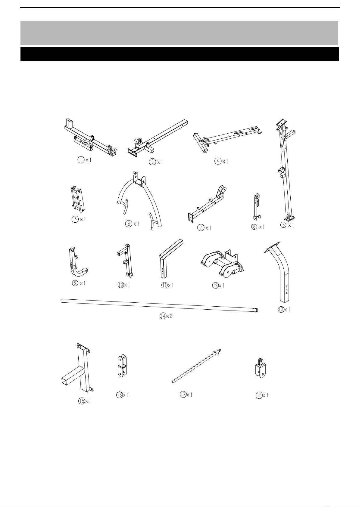
Components - Parts
Please check you have all parts listed below


Note: The quantities below are the correct amount to complete the assembly. In some cases more
hardware may be supplied than are required. Some of thefixings arepre-fittedto thelargercomponents.
Pleasecheck carefully beforecontacting us regardinganymissing fixings.
Components - Fixings
Please check you have all parts listed below

Assembly Instructions
Insert 2 pcs guide rods(14#) into the holes of the Rear Stabilizer(1#) separately and tighten them with
2 pcs M10*20 Allen Bolt(34#) and 2pcs φ10 washers(50#).
Note:(76#)&(87#) &(79#) &(82#) were pre-fixed in the factory already.
Step 1

Step 2
Assembly Instructions
Attach the main base frame(2#) to the rear stabilizer (1#) , Carefully align the holes and secure them
with 2pcs M10*90 carriage bolt(47#),2pcs bracket (28#),2pcs φ10 washers(50#) and 2pcs M10
Aircraft nuts(53#) .
Note:(76#)&(77#) &(87#) were pre-fixed in the factory already.

Assembly Instructions
A ttach the front vertical frame (3#) onto the main base frame(2#), carefully align the holes and
tighten them together with 2pcs M10*70 carriage bolt(48#),1 pc bracket(29#),2pcs φ10 washers(50#)
and 2pcs M10 Aircraft nuts(53#) .
Step 3

Assembly Instructions
Step 4
11
Slide the 2pcs rubber bumper (59#) along the guide rods (14#) separately from the top to the bottom.
Place 15pcs weight plate(100#) along the guide rods(14#) from the top to the bottom and Insert the
Selector Rod(17#) into the center hole of the weight plates(#100).And then put the weight stem
(101#) with the same way,Select the desired weight with the lock pin(65#) when exercising.
Note: End cap (73#)was pre-fixed in the factory already.

Assembly Instructions
A. Attach the end of the Upper Frame(4#) onto the Guide Rod(14#), Align the holes and secure them
with 2pcs M10*20 allen bolt(34#),2pcs φ10 washers(50#) .
B. Attach upper Frame(4#) onto the front vertical Frame(3#) and secure them with 2pcs M10*70
carriage bolt(48#),1 pc bracket(#29),2pcs φ10 washers(50#) and 2pcs M10 Aircraft nuts(53#) .
Note: (76#)&(79#)&(90#)&(104#) were pre-fixed in the factory already.
Step 5

Assembly Instructions
A. Attach the seat pad support frame (7#) to the front vertical frame(3#),Secure them together with
2pcs M10*70 carriage bolt(48#),1pc bracket(29#) ,2pcs φ10 washers(50#) and 2pcs M10 lock
nuts(53#) .
B. Attach the front short support (8#)onto the main base frame(2#),Secure them together with 1pcs
M10*90 carriage bolt(47#),1pcs φ10 washers(50#) and 1pcs M10 lock nuts(53#) ,Attach the front
short support (8#)with the seat pad support frame(7#) together,Secure them with 1pcs M10*70
carriage bolt(48#),1pcs φ10 washers(50#) and 1pcs M10 lock nuts(53#)
C. Insert the backrest support frame(#15) to the opening of the front vertical frame(#3) and select the
desired position with M18 lock knob (#61) when exercising.
Step 6

Assembly Instructions
Step 7
A. Attach the front press base frame(5#) to the upper frame (4#) and secure them together with
1pcs axle(45#),2pcs φ10 washers (49#) and 2pcs M10 Aircraft nuts(53#) .
B. Attach butterfly frame(6#) to the front press base (5#) and secure them together with 1pc Axle
(46#),2pcs φ10 washers(49#) and 2pcs M10 Aircraft nuts(53#) .
Note: (#72)(#74)(#80)(#90)(#91)(#95) were fre-fixed in the factory already.
Assembly Instructions
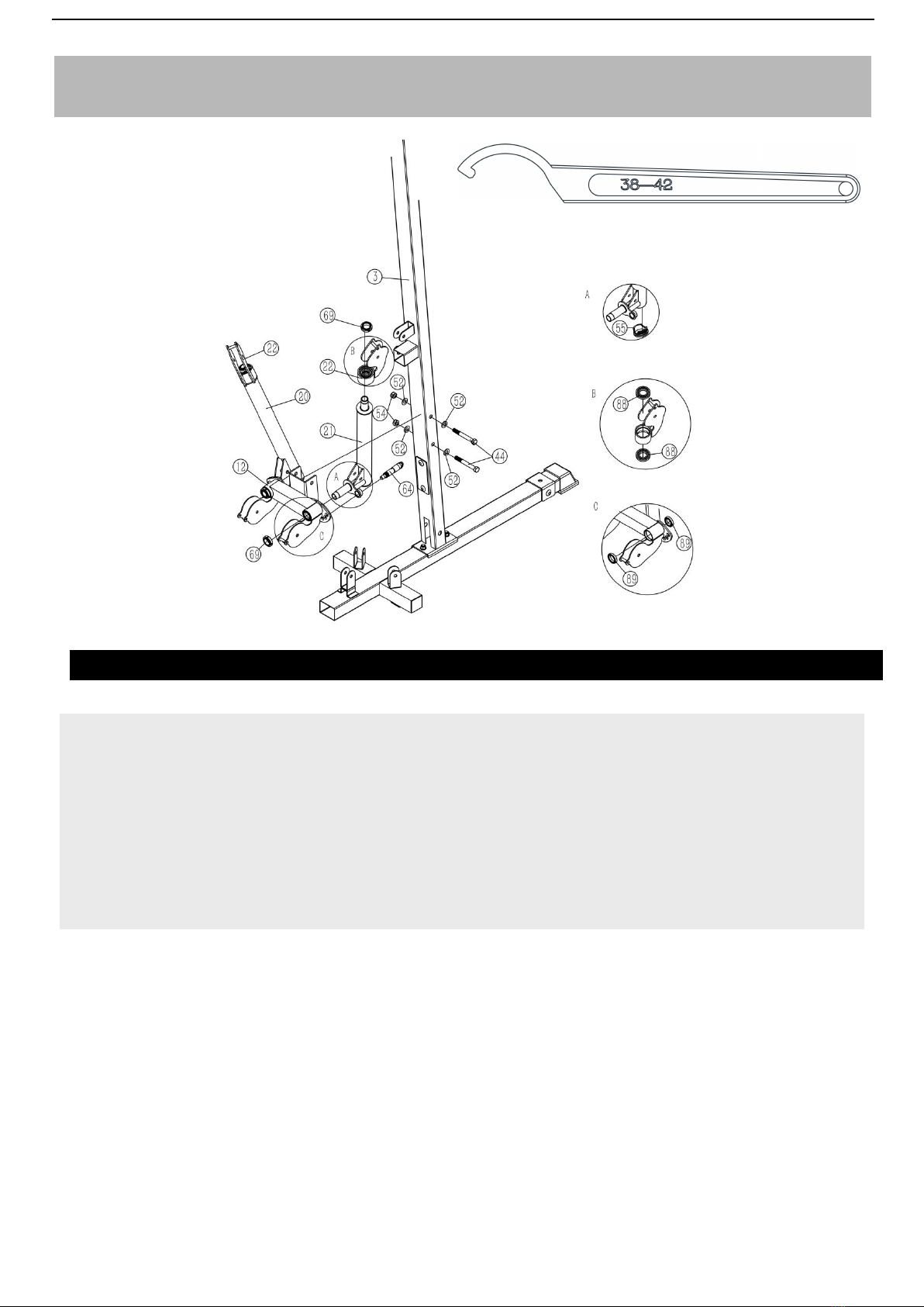
Step 8
A.Attach the bracket frame(12#) to the vertical frame (3#) and secure them together with 2pcs
M12*95 mm hex bolt (44#),4pcs φ12 washer(52#) and 2p cs M12 Aircraft nuts(54#) .
B.Attach the Left frame(20#) & right frame(21#)to th e bracket (12#) separately,,and fix them with 2pcs
M24*1.5 aircraft circle bolt(69#),then tighten with a r ound nut hook wrench as the above diagram
shows.(Factory provide the wrench).
C.Select the designed Left frame(20#) & right fram
e(21#) position with the 2pcs T shape pin (64#).
Note: (#55)&(#88)&(#89) were pre-fixed in the fact
ory already.

Assembly Instructions

Step 9
A.Attach the leg developer holder (9#) to the seat pad support frame(7#) and secure them with 1pc
axle (43#),2pcs washer (#49) ,2pcs M10 aircraft nut(53#).
B.Attach leg press support(10#) onto the leg develop holder(9#) and secure them together with 1pc
axle (43#),2pcs washer (#49) ,2pcs M10 aircraft nut(53#).Insert the L shape pin(#63) to keep it safe
when not use.
C.Insert the foot plate support (#11) into the opening of the leg press support (#10) and select the
desired height with the lock pin (#61)。
D.Insert the arm curl pad support (13#) into rear stabilizer(#1) as the diagram shows.
Note: (#75)&(#76)&(#78)&(#83)&(#84)&(#85)&(#90 ) were pre-fixed in the factory already.

Assembly Instructions

Step 10
•
•
•
•
A .Attach the upper cable (96#)through the opening of the upper frame, Make sure the ball
stopper should be underneath the upper fame.Place 1pc pulley (92#) under the cable, and secure the
pulley with 1pc Allen bolt M10*85 (41#),2pcs bushing(39#) and M10 Aircraft nut (53#).
B. Draw the cable backwards and place the 2 nd pulley below the cable, Seuce the pulley with the
same way in A.
C.Draw the cable around the pulley and forwards, fix the the 3rd pulley with the same way with the
1pc (42#) and 2pcs ϕ10 washer(50#) and M10 Aircraft nut (53#).
D.Draw the cable around and backwards , place the 4rd pulley and secure it with M10*50 Allen bolt
(36#) ,2pcs ϕ10 washer(50#) and M10 Aircraft nut (53#).
•
•
E. Draw the cable around and forwards ,Place the 5rd pulley and secure it with the same way in
C.
F. Draw the cable around and backwards , place the 6 rd pulley onto the cable and secure the
•
•
•
•
•
pulley with the same way in A.
G.Draw the cable around the pulley and upwards, Place the 7nd pulley below the cable and secure
the pulley in D.
H . Draw the cable around the pulley and around downwards, Place the 8nd pulley onto the
cable.Secure the pulley with the cross-double floating bracket with the same way in D.
I, Draw the cable around the pulley and forwards,Place the 9nd pulley below the cable ,and secure
the pulley with the D.
J. Draw the cable around the pulley and downwards, Place the 10 nd pulley onto the cable and
secure it with the double floating bracket (#)and 2pcs pulley cover(#) .
K. Draw the cable around the pulley and through the opening of the upper frame. Secure the 11nd
pulley with the 1pc M10*45Allen bolt (36#), 1pc cable retainer(30#),2pcs bushing(50#) and 1 pc M10
Aircraft nut (53#).
•
•
•
17

Assembly Instructions

Step 11
•
•
•
•
•
•
A.Draw the pectoral cable(99#) through the open and place the 1st pulley below
the cable, Secure the pulley with M10*50 Allen bolt (37#),2pcs ϕ10 washer (50#) and 1 pc
M10 Aircraft nut (53#).
B.Draw the pectoral cable through the tube and place the 2nd pulley onto the cable.Secure
the pulley with 1pc M10*45 Allen bolt(36#),2pc ϕ10 washer (50#) and 1 pc M10 Aircraft nut (53#).
C. Draw the pectoral cable through the open and place the 3nd pulley below the cable ,
Secure the pulley with the 1pc M10*50 Allen bolt (37#), ϕ10 washer (50#)and 1 pc M10 Aircraft nut
(53#).
D.Draw the cable around the pulley and downwards, Place the 4nd pulley onto the cable and
secure it with 1pc M10*45 Allen bolt(36#), ϕ10 washer (50#) and 1 pc M10 Aircraft nut (53#).
E.Draw the cable around the pulley and upwards, Place the 5nd pulley below the
cable.Secure it with the pulley bracket(18#) ,2pcs bushing (57#),2pcs pulley cover (56#), 2pcs ϕ10
washer (50#), 1pc M10*50Allen bolt(37#) and 1 pc M10 Aircraft nut (53#).
F. Draw the cable around the pulley and downwards. And repeat the E,D,C ,B,A, FIx the end
of the pectoral cable with the ball stopper ,1pc buckle, and 1pc M10*30 Allen bolt (35#) and
M10Aircraft nut (53#).
•
•
•
•
Table of contents
Other Garlando Fitness Equipment manuals


Popular Fitness Equipment manuals by other brands


Domyos
Domyos WALKIN Original instructions

Nautilus
Nautilus XP Load P3LCP Maintenance Instruction

Kettler
Kettler UM 678 Series Training and operating instructions

BLUEFIN Fitness
BLUEFIN Fitness BLADE AIR instruction manual

BH FITNESS
BH FITNESS G410 Instructions for assembly and use

Orbit
Orbit VM120 owner's manual


