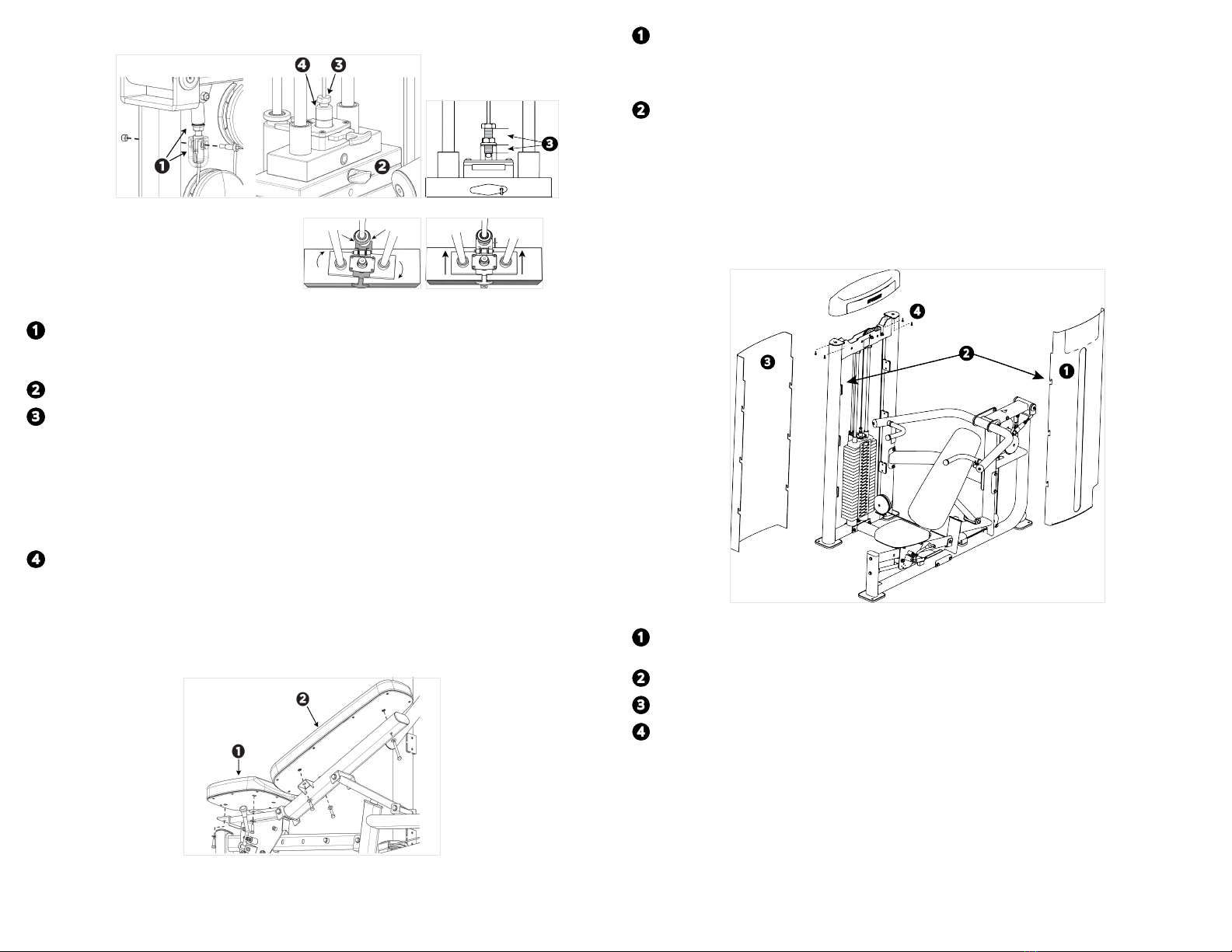
Adjust cable tension
Figure 8 Figure 9
Figure 10: Misaligned Figure 11: Aligned
1. Verify that the cable end is securely seated in its socket, that the socket is bolted securely to
the cable anchor, that at least seven (7) turns/threads on the anchor extend into the movement
arm, and that the locking jam nut on the anchor is tight.
2. Place the weight selection pin in the top weight.
3. Screw the cable bolt into the selector stem until the cable meets the following requirements:
— At least seven (7) turns/threads (minimum) of the cable bolt into the weight selector stem.
— A maximum of 1-1/8 inch (29 mm) between the bottom of the cable bolt head and the
bottom of the flange lock nut.
— No excess slack remains.
— The top weight begins to separate from the second weight.
— The cable is just loose enough to permit insertion of the selector in into each of the weight
plates.
4. Hold the weight tower straight while tightening the locking jam nut against the selector stem.
If you do not hold the weight tower straight, it can twist (see Figure 10).
5. Once tightened, verify alignment between the selector and the add-on weight.
6. Check the adjustment by inserting the weight pin into every weight plate hole. The weight pin
should slide easily in and out of each weight plate.
Attach the pads
Figure 12
1. Attach the seat pad to the bracket on the seat post using:
Note: The narrow end of the seat pad should face the front of the unit.
3 – M10 x 30 mm hex head bolt
3 – 11 mm flat washer
2. Attach the back pad to the back pad mounting locations on the seat frame using:
Note: The narrow end of the back pad should face upward.
1 – M10 x 75 mm hex head bolt (at the top of the pad)
2 – M10 x 30 mm hex head bolts (at the bottom of the pad)
3 – 11 mm flat washers
Install weight stack shroud and top cap
The inside shroud has a slot for weight selection. Both shrouds have three slotted tabs on each side
that fit into the shroud clips mounted to the inside of the weight tower uprights.
Figure 13
1. Align the slotted tabs on the inside shroud with the shroud clips on both sides of the weight
tower.
2. Press the hooks into the clips and lower the shroud securely into place.
3. Repeat steps 1 and 2 to install the outside shroud.
4. Place the top cap on top of the shrouds so that the top edges of the shrouds fit into the slot
between the lip and the ribs of the top cap. Secure the top cap to the weight tower frame using:
4 – M6 x 16 mm pan-head Phillips screws
Note: When you secure the top cap, if the top edges of the shrouds do not fit securely into the
slot between its lip and ribs, remove the cap and the shrouds. Loosen the fasteners securing
each of the shroud clips, then secure each clip again so that it is mounted as high on the weight
stack frame as possible. You will need to push the clips up and hold them in place while you
secure them. After you have repositioned all of the shroud clips, repeat this procedure to install
the shrouds and the top cap.
©2021 Precor Incorporated |VSL Multi-Press|Assembly Guide |P/N CWR247777-102 ENU 31 July 2021 |4